Transmission HONDA INTEGRA 1998 4.G Owner's Guide
[x] Cancel search | Manufacturer: HONDA, Model Year: 1998, Model line: INTEGRA, Model: HONDA INTEGRA 1998 4.GPages: 1681, PDF Size: 54.22 MB
Page 411 of 1681
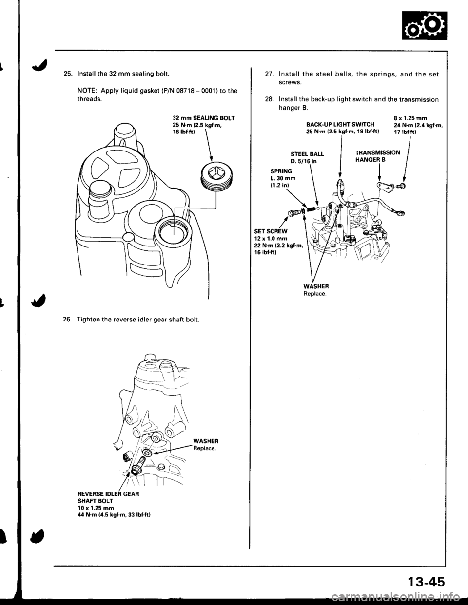
Installthe 32 mm sealing bolt.
NOTE: Apply liquid gasket (P/N 08718 - 0001)to the
threads.
26. Tighten the reverse idler gear shaft bolt.
REVERSEGEARSHAFT BOLT10 x 1.25 mm
32 mm SEALING BOLT
44 N.m 14.5 kgtm,33 lbf.ftl
13-45
STEEL BALI-
27.Install the steel balls, the springs, and the set
scfews.
lnstall the back-up light switch and the transmission
hanger B,
8 x 1.25 mmBACK-UP LlGl{T SWITCH 24 N.m t2.a kgt.rn,25 N.m {2.5 kgf.m, 18 lbf.ftl 17 tbf.ft)
12 x 1.0 mm22 N-ln 12.2 kgl.tn,16 rbf.ftl
Page 412 of 1681
I
Transmission Assembly
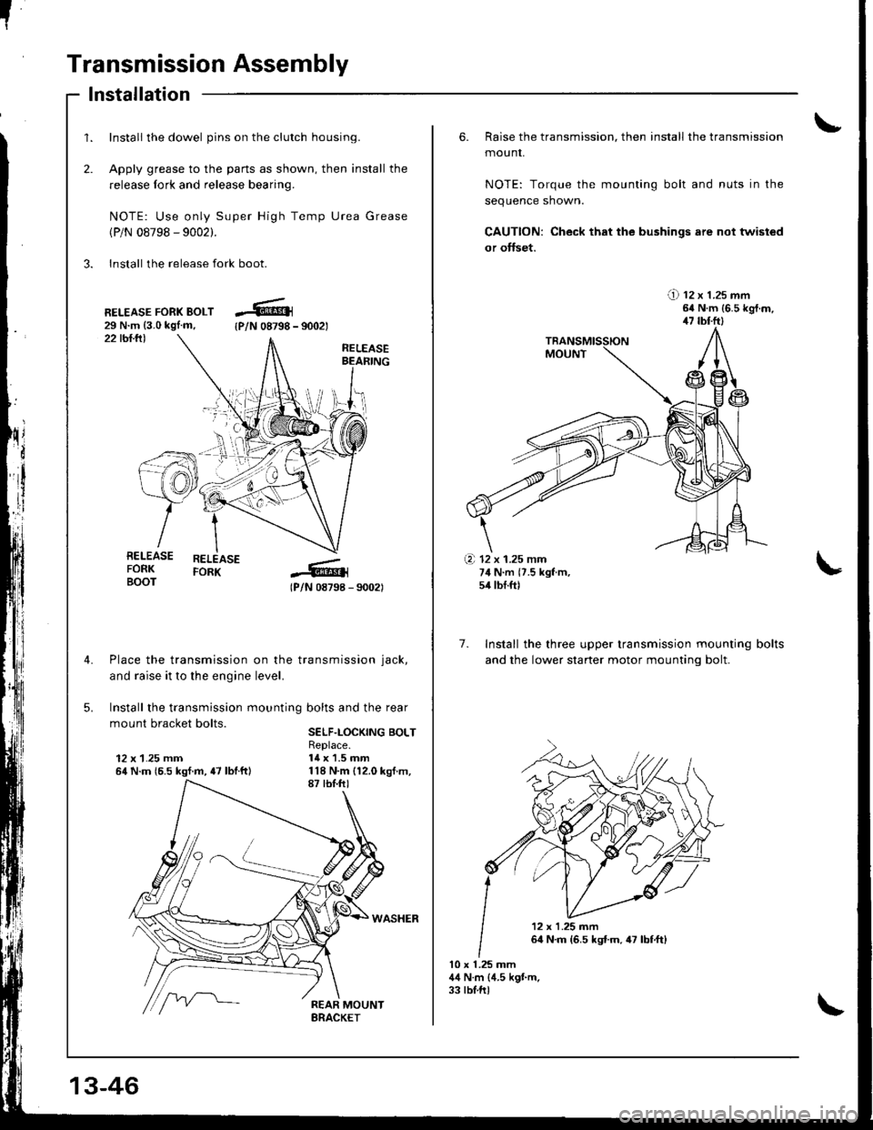
1.
2.
Install the dowel pins on the clutch housing.
Apply grease to the parts as shown, then install the
release fork and release bearing.
NOTE: Use only Super High Temp Urea Grease
(P/N 08798 - 9002).
3. Install the release fork boot.
lnstallation
22 tbl.lll
RELEASE FORK BOLT29 N.m {3.0 kgl.m,{P/N 08798 - 9002t
RELEASEBEAFING
RELEASEFORK
lPlN 08798 - 90021
Place the transmission on the transmission jack,
and raise it to the engine level.
Install the transmission mounting bolts and the rear
mount bracket bolts.SELF.LOCKING BOLT
12 x 1.25 mm64 N.m {6.5 kgf.m, {7 lbtftl
Replace.14 x 1.5 mm
RELEASEFORKBOOT
\i'l-r )i-
.+.i
13-46
6. Raise the transmission, then install the transmission
mounr,
NOTE: Torque the mounting bolt and nuts in the
sequence shown.
CAUTION: Check that the bushings are not twisted
or offset.
!) tz x t.zs mm64 N.m {6.5 kgt.m,47 tbl.ftl
7. Install the three upper transmission mounting
and the lower staner motor mountinq bolt.
bolts
10 x 1.25 mm44 N.m (4.5 kgt m.33 tblftl
(a 12 x 1.25 mm74 N.m {7.5 kgf m,54 tbf.ft)
'12x1.25m�n
64 N.m {6.5 kst.m,47 lbf,ft)
Page 414 of 1681
[!
"
Transmission Assembly
Installation (cont'd)
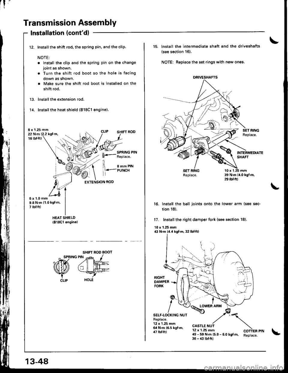
Install the shift rod, the spring pin, and the clip.
NOTE:
. lnstall the clip and the spring pin on the change
joint as shown.
. Turn the shift rod boot so the hole is facing
down as snown.
. Make sure the shift rod boot is installed on the
shift rod.
lnstall the extension rod.
Installthe heat shield (818C1 engine).'t 4.
8 x 1.25 mm22 N.m 12.2 kgfm.16lbt.ft)
I e--erru
1 l+.-PUNCH
EXTENSION ROD
6x1.0mm9.8 N.m 11.0 kgf m,? rbf.ft)
SHIFT ROD BOOT
^ SPRING PIN -- -1
?ffi A'W
Nfu *rry
CLlp HOLE
13-48
DRIVESHAFTS
15. lnstall the intermediate shaft 8nd the driveshafts
(see section 16).
NOTE: Beplace the set rings with new ones.
16. Install the ball joints onto the lower arm (soe ssc-
tion 18).
17. Install the right damper fork (see ssction 18).
10 r 1.25 mm43 N.m lir.a kgt m. 32 lbtftl
LOWER ARM
SELF.LOCKING NUTReplace.12 x 1,25 mm6a N.m 16.5 kg{.ft,/u rbl.tt)
CASTLE NUT12 x 1.25 mm49 - 59 N.m (5.0 - 6.0 kgf.m, Reptace.35 - 43 lbf.ftl
"\
COTTER PIN
Page 416 of 1681
Transmission Assembly
Installation (cont'd)
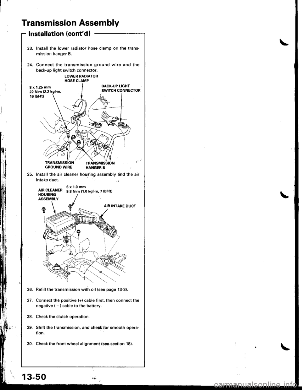
Install the lower radiator hose clamp on the trans-
mission hanger B.
Connect the transmission ground wire and the
back-up light switch connector.
LOWER RADIATORHOSE CLAMP
BACK.UP I-IGHTSWITCH CONNECTOR
24.
TRANSMISSIONGROUND WIRE
25. lnstall the air cleaner
intake duct.
AIR CIfANERHOUSINGASSEMBLY
HANGER B
hoqsing assembly and the air
6x1.0mm9.8 N.m 11.0 kgf.n,7 lbt'ft)
AI8 INTAKE DUCTY1
Reiill the transmission with€il (see page 13-3).
Connect the positive (+) cable first, then connect the
negative ( - ) cable to the battery.
Check the clutch operation.
Shift the transmission, and che6* {or smooth opera-
tion.
30. Check the front wheel alignment (se6 section 18).
21.
24.
13-50
Page 418 of 1681
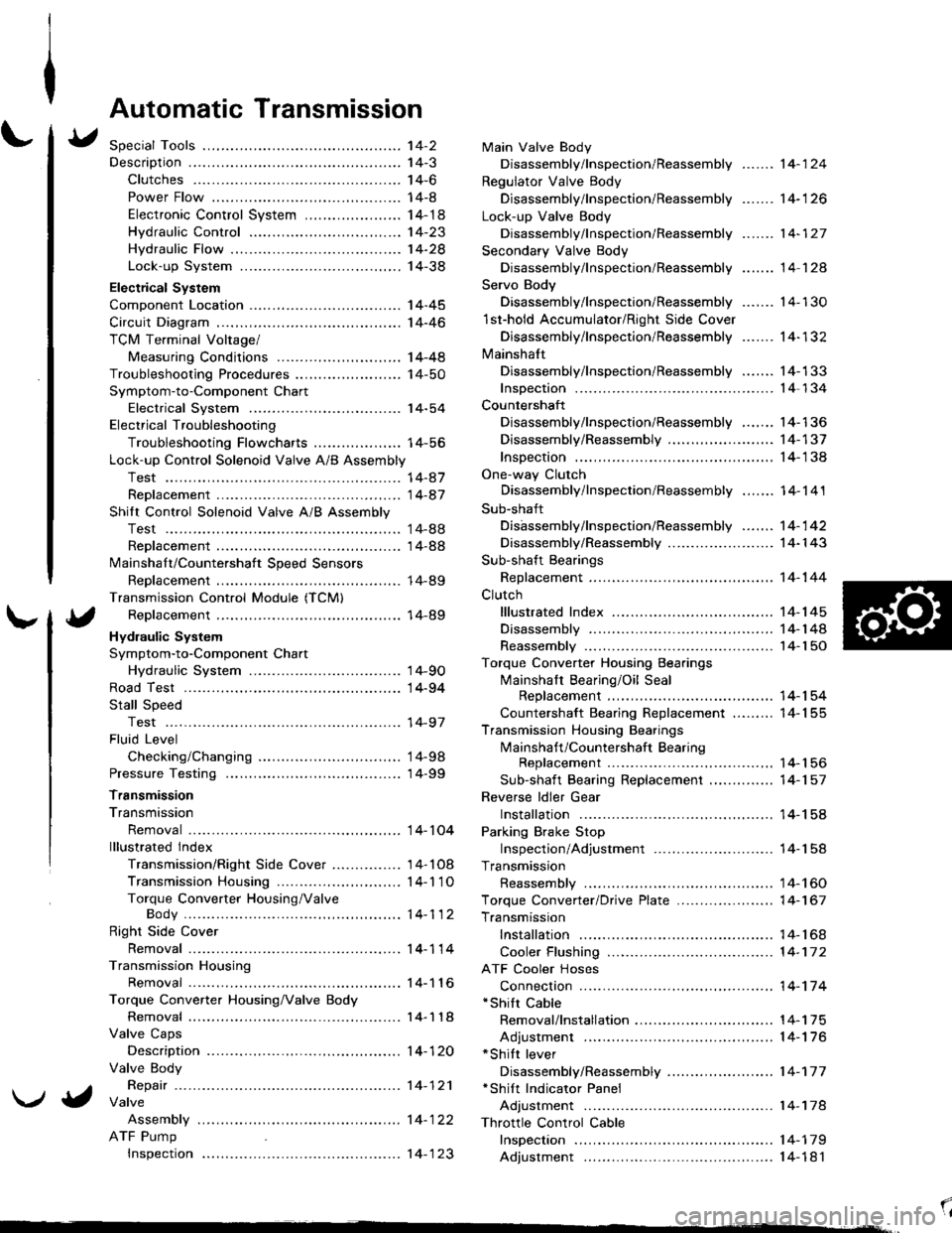
Automatic Transmission
Special Tools ................ '14-2
Descraption .................... 14-3
Clutches ............ ...... 14-6
Power Flow ..,........... 14-8
Electronic Control System ..................... 1 4-1 8
Hydraulic Control ...... 14-23
Hydraulic Flow .........- 14-28
Lock-up System ........ 14-38
Electrical System
Component Location -................................ 1 4-45
Circuit Diagram ............. 14-46
TCM Terminal Voltage/
Measuring Conditions ......,.................... 1 4-48
Troubleshooting Procedures .. . ... ........ ...... ... 14-50
Symptom-to-Component Chart
Electrical System ...... 14-54
Electrical Troubleshooting
Troubleshooting Flowcharts .......... ... ...,.. 14-56
Lock-up Control Solenoid Valve A/B Assembly
Test .................. ...... 14-A7
Replacement ............. 14-a7
Shilt Control Solenoid Valve A/B Assembly
Test .................. ...... '14-88
Replacement .,..,........ 14-88
lvlainshaf t/Countershaft Speed Sensors
Replacement ....-......,. 14-89
Transmission Control Module (TCM)
Replacement ............. 14-89
Hydraulic System
Symptom-to-Component Chart
Hydraulic System ...... 14-90
Road Test ,................... 14-94
Stall Speed
Test .................. ...... 14-97
Fluid Level
Checking/Changing .... 14-98
Pressure Testing ........... 14-99
Transmission
Transmission
Removal ............. ...... 14-10�4
lllustrated lndex
Transmission/Right Side Cover ............... 1 4-1 08
Transmission Housin9 ................,..,....... 1 4-1'1 O
Torque Converter Housing/ValveBody .................. .. 14-112
Right Side Cover
Removal ............. ...... 14-114
Transmission Housing
Removal ............. ...... 14-1 l6
Torque Converter Housing/Valve Body
Removal ............. ...... l4-1 18
Valve Caps
Description ...........-... 14-120
Valve Body
Repair ................ ...... 14-12'l
Valve
Assembly
ATF Pump
Inspeclton
Main Valve Body
Disassembly/lnspection/Reassembly
Regulator Valve Body
Disassembly/lnspection/Reassembly
Lock-up Valve Body
Disassembly/lnspection/Reassembly
Secondary Valve Body
Disassembly/lnspection/Reassembly
Servo Body
....... 14-124
....... 14-126
....... 14-127
....... 14 124
Disassembly/lnspection/Reassembly .......
1st-hold Accumulator/Right Side Cover
Disassembly/lnspection/Reassembly .......
Mainsha{t
14-130
14-132
Disassembly/lnspection/Reassembly ....... 14-133
Inspection ................. 14-134
Countershaft
Disassembly/lnspection/Reassembly,..,.., l4-136
Disassembly/Reassembly ..,...,..,.........,,.. 1 4-1 37
Inspection ......,...,..,... 14-138
One-way Clutch
Disassembly/lnspection/Reassembly ....,.. 14-141
Sub-shaft
Disassembly/lnspection/Reassembly ...,,..'14-142
Disassembly/Reassembly ....................... 1 4- l 43
Sub-shaft Bearings
Replacement ,..,,.,,..,.. 14-144
Clutch
lllustrated Index ................................... I 4-1 45
Disassembly ............. 14-144
Reassembly .............. 14-150
Torque Converter Housing Bearings
Mainshaft Bearing/Oil Seal
Replacement ......... 14-154
Countershaft Bearing Replacement ......... 1 4- 1 55
Transmission Housing Bearings
Mainshaft/Countershaft BearingReplacement ......,.. 14-'156
Sub-shaft Bearing Replacement .,............ 1 4-1 57
Reverse ldler Gear
Installation .........-..... 14-158
Parking Brake Stop
Inspection/Adjustment .......................... 1 4-1 58
Transmission
Reassembly .............. 14-160
Torque Converler/Drive Plate ..............,.,,.,, 1 4-1 67
Transmission
Installation ............... 14-168
Cooler Flushing ......... 14-172
ATF Cooler Hoses
Connection ,..,,,....,,.,, '14-'174
*shift cable
Removal/lnstallation . . .. .... ... .... ... .... .. . ... .. 14-'l75
Adjustment ,..,...,,,,.,, 14-'116*Shilt lever
Disassembly/Reassembly ....................... 1 4-'17 7'Shift Indicator Panel
Adjustment .............. 14-178
\l
)g
Page 420 of 1681
Description
\J
t{
{
14-3
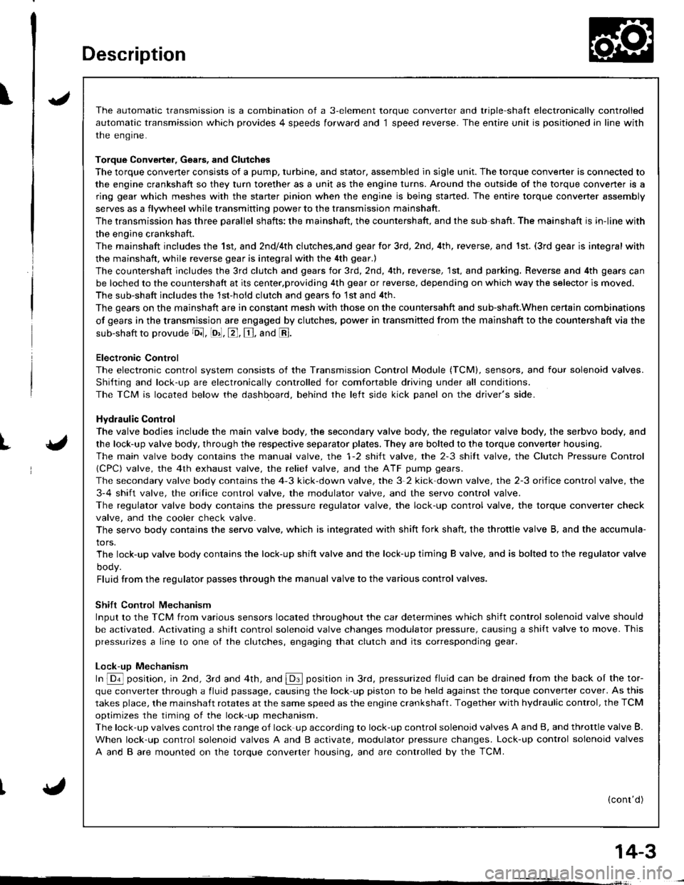
The automatic transmission is a combination of a 3-element torque converter and triple-shalt electronically controlled
automatic transmission which provides 4 speeds forward and 1 speed reverse. The entire unit is positioned in line with
the engrne.
Torque Converter, Gears, and Clutches
The torque converter consists of a pump, turbine, and stator, assembled in sigle unit. The torque converter is connected to
the engine crankshaft so they turn torether as a unit as the engine turns. Around the outside of the torque convener is a
ring gear which meshes with the starter pinion when the engine is being started. The entire torque converter assembly
serves as a flywheel while transmitting power to the transmission mainshaft.
The transmission has three parallel shafts; the mainshaft. the countershaft, and the sub shaft. The mainshaft is in-line with
the engine crankshaft.
The mainshaft includes the 1st, and 2ndl4th clutches,and gear for 3rd, 2nd, 4th, reverse, and 1st. (3rd gear is integral with
the mainshaft, while reverse gear is integral with the 4th gear.)
The countershaft includes the 3rd clutch and gears for 3rd,2nd, 4th, reverse, 1st, and parking. Reverse and 4th gears can
be loched to the countershaft at its center,providing 4th gear or reverse, depending on which way the selector is moved.
The sub-shaft includes the 1st-hold clutch and gears fo 1st and 4th.
The gears on the mainshaft are in constant mesh with those on the countersahft and sub-shaft.When certain combinations
of gears in the transmission are engaged by clutches. power in transmitted from the mainshaft to the countershaft via the
sub-shaft to orovude oil, lo'1. E, E. and E.
Electronic Control
The electronic control svstem consists of the Transmission Control Module (TCM), sensors, and four solenoid valves.
Shilting and lock-up are electronically controlled for comfortable driving under all conditions.
The TCM is located below the dashboard, behind the lelt side kick panel on the driver's side.
Hydraulic Control
The valve bodies include the main valve body, the secondary valve body, the regulator valve body, the serbvo body, and
the lock-up valve body, through the respective separator plates, They are bolted to the torque converter housing,
The main valve body contains the manual valve, the 1-2 shift valve, the 2-3 shitt valve, the Clutch Pressure Control
lCPC) valve, the 4th exhaust valve, the reliel valve, and the ATF pump gears.
The secondary valve body contains the 4-3 kick-down valve, the 3-2 kick-down valve, the 2-3 orifice control valve, the
3-4 shift valve, the orilice control valve, the modulator valve, and the servo control valve.
The regulator valve body contains the pressure regulator valve, the lock-up control valve, the torque converter check
valve, and the cooler check valve.
The servo body contains the servo valve, which is integrated with shift fork shaft, the throttle valve B, and the accumula-
tors.
The lock-up valve body contains the lock-up shift valve and the lock-up timing B valve, and is bolted to the regulator valve
ooqy.
Fluid from the regulator passes through the manual valve to the various control valves.
Shift Control Mechanism
Input to the TCM from various sensors located throughout the car determines which shift control solenoid valve should
be activated. Activating a shitt control solenoid valve changes modulator pressure, causing a shift valve to move. This
pressurizes a line to one ol the clutches, engaging that clutch and its corresponding gear.
Lock-uD Mechanism
In @ position, in 2nd, 3rd and 4th, and @ position in 3rd, pressurized fluid can be drained lrom the back oI the tor-
que converter through a fluid passage, causing the lock-up piston to be held against the torque converter cover. As this
takes place, the mainshaft rotates at the same speed as the engine crankshaft. Together with hydraulic control, the TCM
optimizes the timing of the lock-up mechanism.
The lock-up valves controlthe range of lock-up according to lock-up control solenoid valves A and B, and throttle valve B.
When lock-up control solenoid valves A and B activate, modulator pressure changes. Lock-up control solenoid valves
A and B are mounted on the torque converter housing, and are controlled by the TCM.
(cont'd)
Page 423 of 1681
Description
Clutches
t
{
The four-speed automatic transmission uses hydraulically-actuated clutches to engage or disengage the transmission gears.
When hydraulic pressure is introduced into the clutch drum. the clutch piston is applied. This presses the friction discs
and steel plates together, locking them so they don't slip. Power is then transmitted through the engaged clutch pack
to its hub-mounted gear.
Likewise, when hydraulic pressure is bled from the clutch pack, the piston releases the friction discs and steel plates,
and they are free to slide past each other while disengaged. This allows the gear to spin independently on its shaft, trans-
mrrrng no power.
lsr Clutch
The 1 st clutch engages/disengages 1st gear, and is located at the end of the msinshaft, just behind the right side cover.
The 1st clutch is supplied hydraulic pressure by its ATF feed pipe within the mainshaft.
l st-hold clurch
The '1 st-hold clutch engages/disengages 'lst-hold or E] position, and is located at the middle of the sub-shaft. The 1st-
hold clutch is supplied hydraulic pressure by its ATF feed pipe within the sub-shaft.
2nd Clutch
The 2nd clutch engages/disengages 2nd gear, and is located at the middle of the mainshaft. The 2nd clutch is joined
back-to-back to the 4th clutch. The 2nd clutch is supplied hydraulic pressure through the mainshaft by a circuit connected
to the internal hydraulic circuit.
3rd ClutchThe 3rd clutch engages/disengages 3rd gear, and is located at the end of the counte.shaft, opposite the right side cover.
The 3rd clutch is supplied hydraulic pressure by its ATF feed pipe within the countershaft.
4th Clutch
The 4th clutch engages/disengages 4th gear, as well as reverse gear, and is located at the middle of the mainshaft.
The 4th clutch is joined back-to-back to the 2nd clutch. The 4th clutch is supplied hydraulic pressure by its ATF feed
oiDe within the mainshaft.
One-way Clutch
The one-way clutch is positioned between the parking gear and the countershaft 1st gear. with the parking gear splined
to the countershalt. The countershaft 1st gear provides the outer race, and the parking gear provides the inner race sur-
face. The one-way clutch locks up when power is transmitted from the msinshaft 1st gear to the countershaft I st gear.
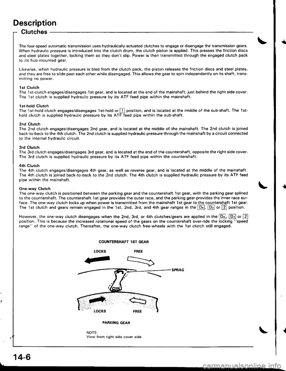
The 1st clutch and gears remain engaged in the 1st, 2nd. 3rd, and 4th gear ranges in the Lqd, Lq9.l or La position.
However, the one-way clutch disengages when the 2nd, 3rd, or 4th clutches/gears are applied in the E, lDll o, Eposition. This is because the increased rotational speed of the gears on the countershatt over-ride the locking "speed
range" ot the one-way clutch. Thereatter, the one-way clutch free-wheels with the lst clutch still engaged.
COUiITERSHAFT lST GEAR
FREE
-".--)
LOCKS
F
LOCKS FREE
PARKING GEAR
NOTE:View from right side cover side.
14-6
Page 435 of 1681
Description
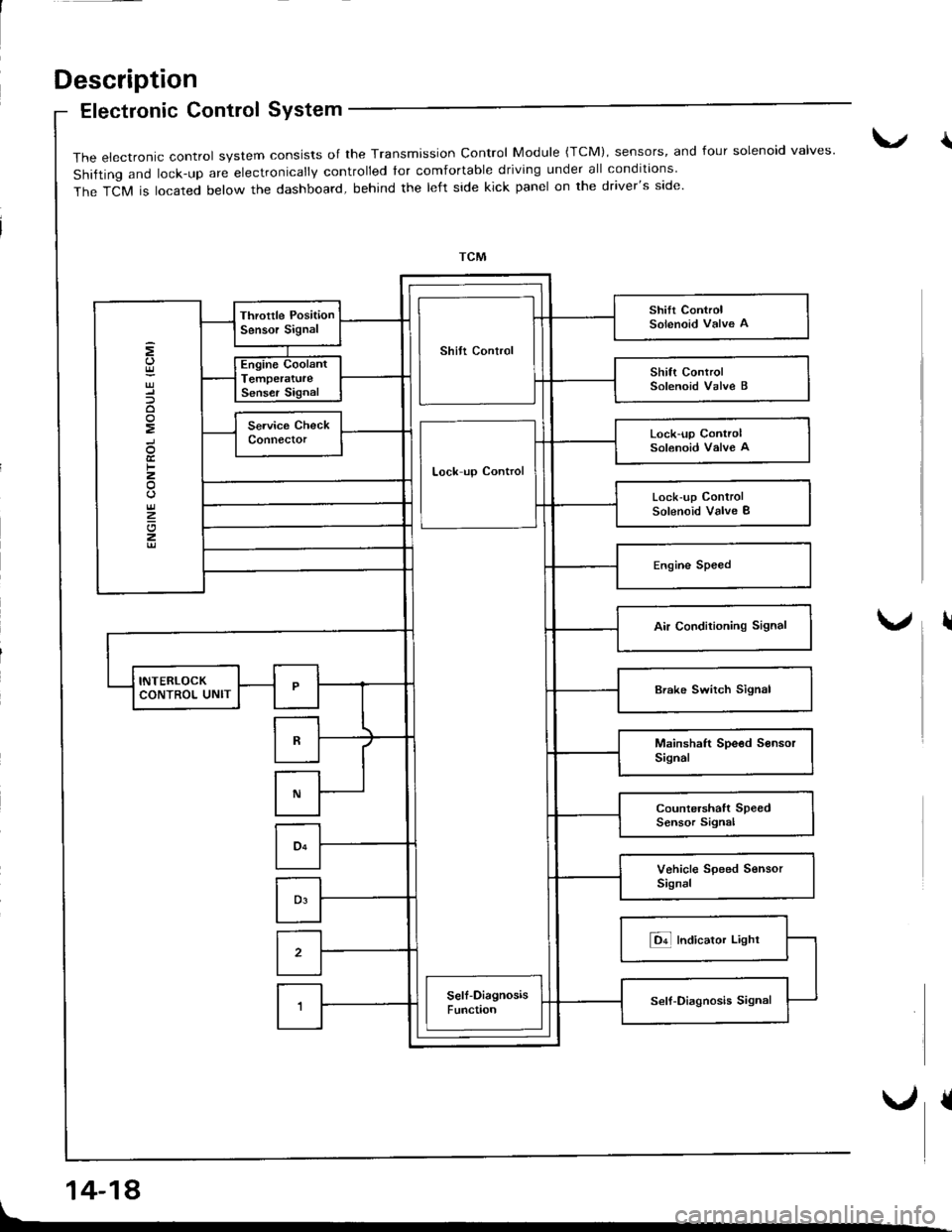
Electronic Control SYstem
14-18
{The electronic control system consists of the Transmission control Module {TcM), sensors, and four solenoid valves'
shifting and lock-up are electronically controlled tor comfortable driving under all conditions
The TCM is located below the dashboard, behind the left side kick panel on the driver's side.
Shilt Control
Lock-up ControlSolenoid Valve A
Lock up Control
Lock-up ControlSolenoid Valve I
I
Page 438 of 1681
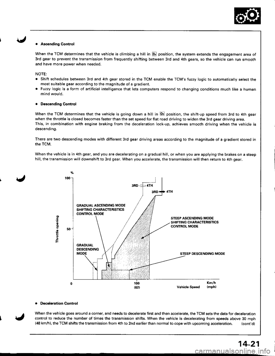
. Ascending Control
When the TCM determines that the vehicle is climbing a hill in E position, the system extends the engagement area of
3rd gear to prevent the transmission from frequently shifting between 3rd and 4th gears, so the vehicle can run smooth
and have more power when needed,
NOTE:
Shift schedules between 3rd and 4th gear stored in the TCM enable the TCM'S fuzzy logic to automatically select themost suitable gear according to the magnitude of a gradient.
Fuzzy logic is a form of artificial intelligence that lets computers respond to changing conditions much like a human
mind would,
. Descending Control
When the TCM determines that the vehicle is going down a hill in E position, the shift-up speed from 3rd to 4th gear
when the throttle is closed becomes faster than the set speed for flat road driving to widen the 3rd gear driving area.This. in combination with engine braking from the deceleration lock-up, achieves smooth driving when the vehicle is
descending,
There are two descending modes with different 3rd gear driving areas according to the magnitude of a gradient stored in
the TCM.
When the vehicle js in 4th gear, and you are decelerating on a gradual hill, or when you are applying the brakes on a steephill, the transmission will downshift to 3rd gear. When you accelerate, the transmission will then return to 4th gear,
GRAOUAL ASCENOING MOOESHIFTING CHARACTERISTICSCONTROL
STEEP DESCENDING MODE
Vehicle Speed
. Deceleraiion Control
When the vehicle goes around a corner, and needs to decelerate first and then accelerate. the TCM sets the data for deceleration
control to reduce the number of times the transmission shifts. When the vehicle is decelerating from speeds above 30 mph(,18 km/h), the TCM shifts the transmission from 4th to 2nd earlierthan normal to cope with upcoming acceleration. (cont'd)
E
F
Km/h(mph)
14-21
Page 446 of 1681
I
I
I
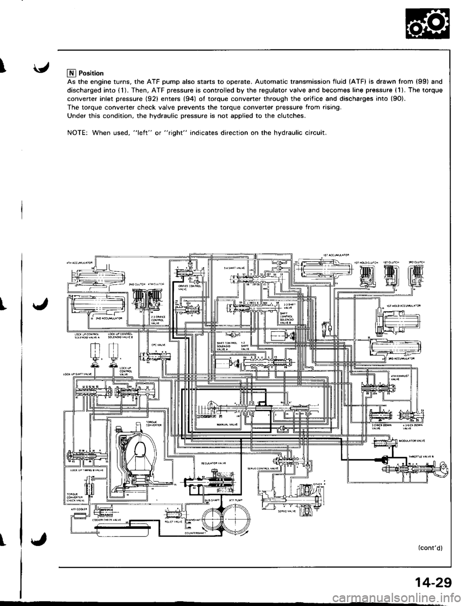
Llfl Position
As the engine turns, the ATF pump also starts to operate. Automatic transmission fluid (ATF) is drawn from (99) and
discharged into (1). Then, ATF pressure is controlled by the regulator valve and becomes line pressure (1). The torque
converter inlet pressure {92} enters (94) ol torque converter through the orilice and discharges into {9O).
The torque converter check valve prevents the torque converter pressure from rising.
Under this condition, the hydraulic pressure is not applied to the clutches.
NOTE: When used, "l€ft" or "right" indicates direction on the hydraulic circuit.
(cont'dl
14-29