ECO mode HONDA INTEGRA 1998 4.G Workshop Manual
[x] Cancel search | Manufacturer: HONDA, Model Year: 1998, Model line: INTEGRA, Model: HONDA INTEGRA 1998 4.GPages: 1681, PDF Size: 54.22 MB
Page 208 of 1681
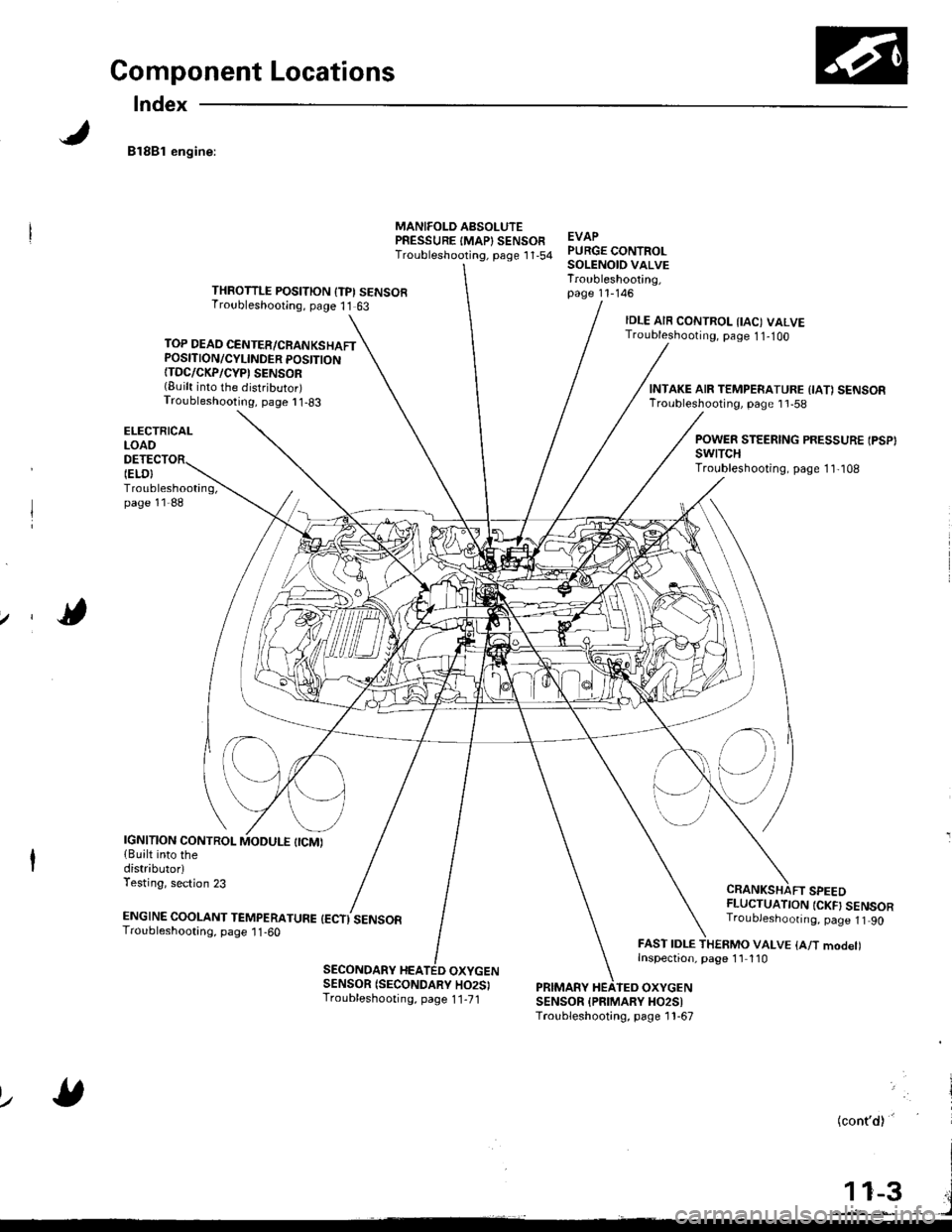
Component Locations
Index
81881 engine:
TOP DEAD CENTER/CRANKSHAFTPOSITION/CYLINDER POSITION{TDC/CKP/CYP' SENSOR(Built into the distributor)Troubleshooting, page I 1-83
ELECTRICALLOAO
Troubleshooting,page 11-88
MANIFOLD AsSOLUTEPRESSURE IMAP} SENSOFTroubleshooting, psge 1 '1,54EVAPPURGE CONTROLSOLENOID VALVETroubleshooting,page 11-146THROTTLE POSITION {TPI SENSORTroubleshooting, page 11 63
IELO}
IDLE AIR CONTROL IIAC) VALVETroubleshooting, page 1 1-1OO
CRANKSHAFT SPEEDFLUCTUATION {CKF} SENSORTroubJeshoonng. page 1t 90
FAST IDLE THERMO VALVE {A/T modet)Inspection, page 1'l 110
INTAKE AIR TEMPERATURE {IA1 SENSORTroubleshooting, page 1 'l -58
POWER STEERING PRESSURE IPSP}swtTcHTroubleshooting, page 1 1,108
IGNITION CONTROL{Built into thedistributorlTesting, section 23
ENGTNE cooLANT TEnapenerune {ectisensoaTroubleshooting, page 1 1 -60
SECONDARY HEATED OXYGENSENSOR (SECONDARY HO2SITroubleshooting, page 1 1-71PRIMARY HEATEO OXYGENSENSOR {PFIMARY HO2SITroubleshooting, page 1 1-67
lz
(cont'd)'
Page 253 of 1681
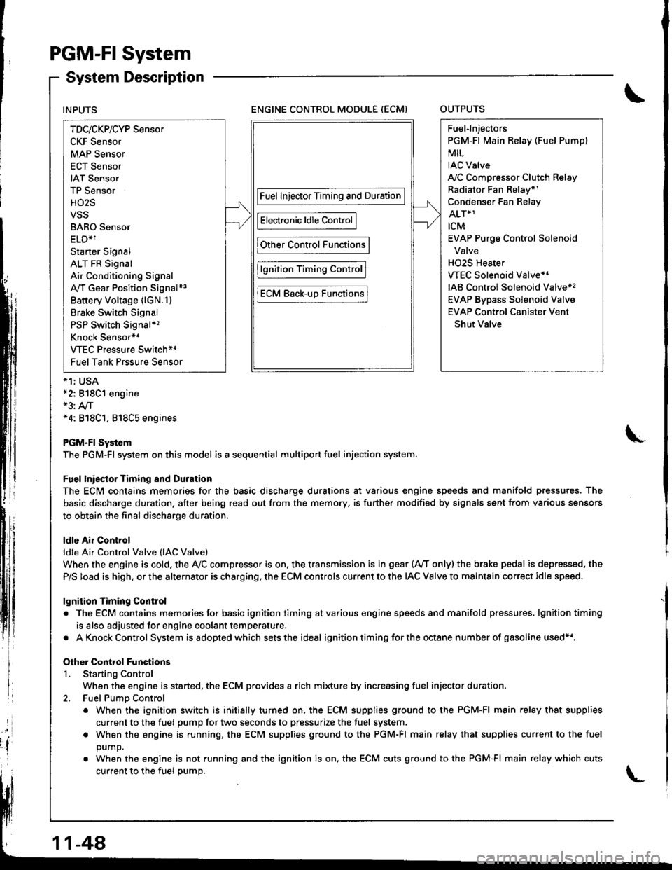
PGM-FI System
System Description
ENGINE CONTROL MODULE (ECM)OUTPUTS
*1: USA*2: 818C1 engine*3: A,/T*4: 818C1, 818C5 engines
PGM-FI Sy3tem
The PGM-Fl system on this model is a sequential multiport fuel injection system.
Fuel lniector Timing and Duration
The ECM contains memories for the basic discharge durations at various engine speeds and manifold pressures. The
basic discharge duration, after being read out from the memory. is further modified by signals sent from various sensors
to obtain the final discharge duration.
ldle Air Control
ldle Ai. Control Valve (lAC Valve)
When the engine is cold, the Ay'C compressor is on. the transmission is in gear (Ay'T only)the brake pedal is depressed, the
P/S load is high, or the alternator is charging, the ECM controls current to the IAC Valve to maintain correct idle speed.
lgnition Timing Control
. The ECM contains memories for basic ignition timing atvarious engine speeds and manifold pressures, lgnitiontiming
is also adjusted for engine coolant temperature.
. AKnockControl System isadoptedwhich sets the ideal ignition timing for the octane n um ber of gasoline used*r,
Other Control Functions
L Starting Control
When the engine is started, the ECM provides a rich mi{ure by increasing fuel injector duration.
2. Fuel PumD Control
. When the ignition switch is initially turned on, the ECM supplies ground to the PGM-FI main relay that supplies
current to the fuel pump for two seconds to pressurize the fuel system.
. When the engine is running, the ECM supplies ground to the PGM-FI main relay that supplies current to the fuel
DUmO.
. When the engine is not running and the ignition is on. the ECM cuts ground to the PGM-FI main relay which cuts
current to the fuel oumo.
INPUTS
TDc/CKP/CYP Sensor
CKF Sensor
MAP Sensor
ECT Sensor
IAT Sensor
TP Sensor
HO2S
VSS
BARO Sensor
ELD*1
Starter Signal
ALT FR Signal
Air Conditioning Signal
A,/T Gear Position Signal*3
Battery Voltage (lGN.1)
Brake Switch Signal
PSP Switch Signal*'�
Knock Sensor*1
VTEC Pressure Switch*4
Fuel Tank Prssure Sensor
Fuel InjectorTiming and Duration
Electronic ldle Control
Other Control Functions
lgnition Timing Control
ECM Back-uD Functions
Fuel-lnjectors
PGM-Fl Main Relay (Fuel Pump)
MIL
IAC Valve
A,/C Compressor Clutch Relay
Radiator Fan Belay*1
Condenser Fan Relay
ALT*1
rcM
EVAP Purge Control Solenoid
Valve
H02S Heater
VTEC Solenoid Valve*'
IAB Control Solenoid Valve*,
EVAP Bypass Solenoid Valve
EVAP Control Canister Vent
Shut Valve
11-48
Page 254 of 1681
3.Fuel Cut-off Control
. Du ring dece leration with the th rottle va lve closed, cu rrent to the fuel injectors is cutoffto improvefuel economyat
speeds over following rpm:. B'1881 engine: 970 rpm {Canada model: 1.050 rpm). B18C1 engine:970 rpm {Canada model: 1.050 rpm). 818C5 engine: 1,300 rpm (Canada model: 1,400 rpm)
. Fuel cut-off action also takes place when engine speed exceeds 7,000 rpm (B'1881 engine), 8.100 rpm (818C1
engine) or 8,600 rpm (818C5 engine), regardless ol the position of the thronle valve, to protect the engine from
over-revving.
A,,/C ComDressor Clutch Relav
When the ECM receives a demand for cooling from the air conditioning system, it delays the compressor from being
energized, and enriches the mixture to assure smooth transition to the A,/C mode.
Evaporative Emission (EVAP) Purge Control Solenoid Valve
When the engine coolanl temperature is above '154'F (68'C) and the air conditioner on. the ECM controls the EVAPpurge control solenoid valve which controls vacuum to the EVAP purge control canister.
Intake Air Eypass (lAB) Control Solenoid Valve*a
When the engine rpm is below 5,750 rpm, rhe IAB control solenoid valve is activated by a signal from the ECM, intake
air flows through the long intake path, then high torque is delivered. At speeds higher than 5,750 rpm, the solenoidvalve is deactivated by the ECM, and intake air flows through the short intake path in order to reduce the resistance in
airflow.
Sell-diagnosis Function lMalfunction Indicator Lamp {MlL)lWhen an abnormality occurs in a signal from a sensor, the ECM supplies ground for the MIL and stores the code in
erasable memory. When the ignition is initially turned on, the ECM supplies ground for the N4lL tor two seconds to
check the MIL bulb condition.
Two Driving Cycle Detection Method
To prevent false indications, the Two Driving Cycle Detection Method is used for the HO2S, fuel metering-related, idle
control system, ECT sensor, TWC and EVAP control system and other self-diagnostic functions, When an abnormality
occurs, the ECM stores it in its memory. When the same abnormality recurs after the ignition switch is turned OFFand ON (ll)again, the ECM informs the driver by lighting the MlL.
However, to ease troubleshooting, this function is cancelled when you shon the service check connector. The MIL will
then blink immediately when an abnormality occurs.
4.
5.
6.
3.
4.
ECM Fail-safe/8ack.up F0nctions
1. Fail-sate Function
When an abnormality occurs in a signal from a sensor, the ECM ignores that signal and assumes a pre-programmed
value for that sensor that allows the enqine to continue to run.
2. Back-uo Function
When an abnormality occurs in the ECM itself, the fuel injectors are controlled by a back-up circuit independent of the
system in order to permit minimal driving.
11-49
Page 338 of 1681
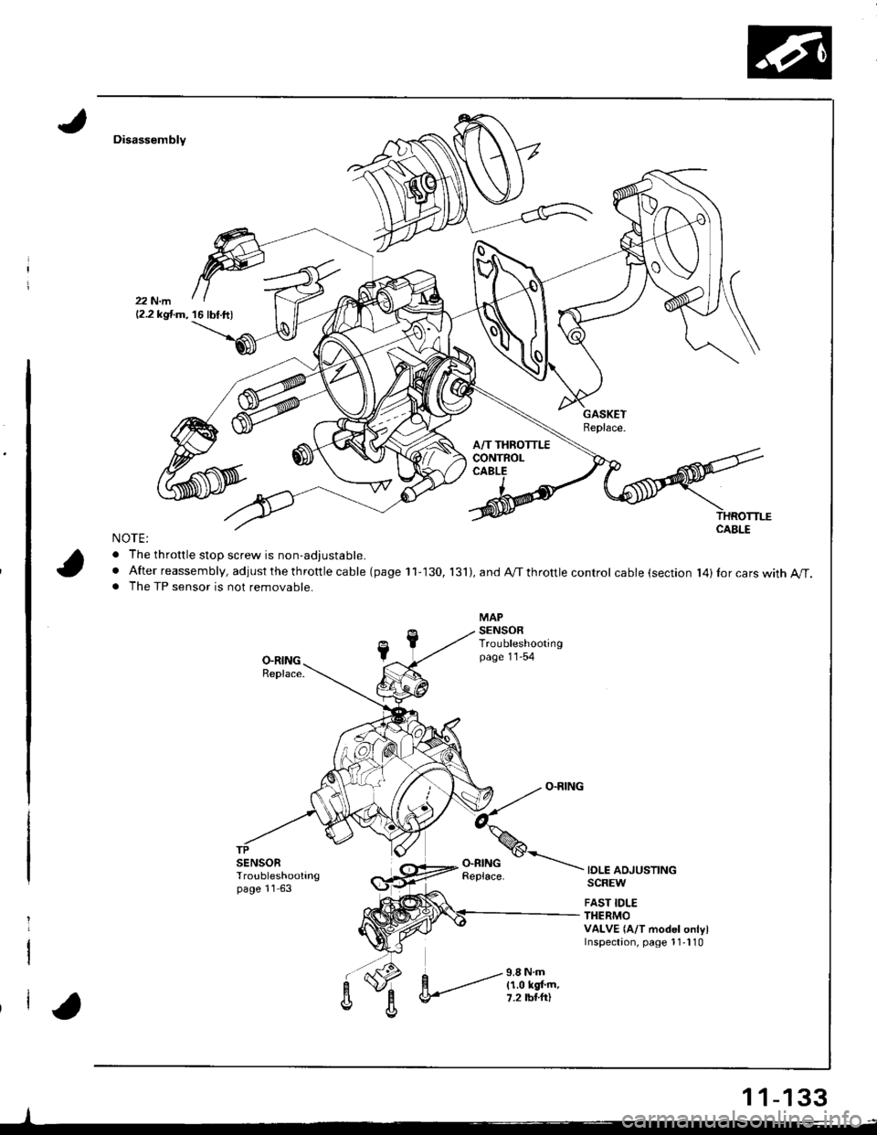
Disassembly
NOTE:
. The throttle stoD screw is non-adiustable.
. After reassembly, adjust the th rottle ca ble (page 11-130, 131),andA/Tthrottlecontrol cable (section l4)Ior cars with A/T.. The TP sensor is not removable.
IOLE ADJUSTINGSCREW
FAST IDLETHERMOVALVE {A/T model onlylInspectaon, page 1 1-l 10
-l
12.2 kgf.m, 16 lbf.ft)
1 1-133
Page 438 of 1681
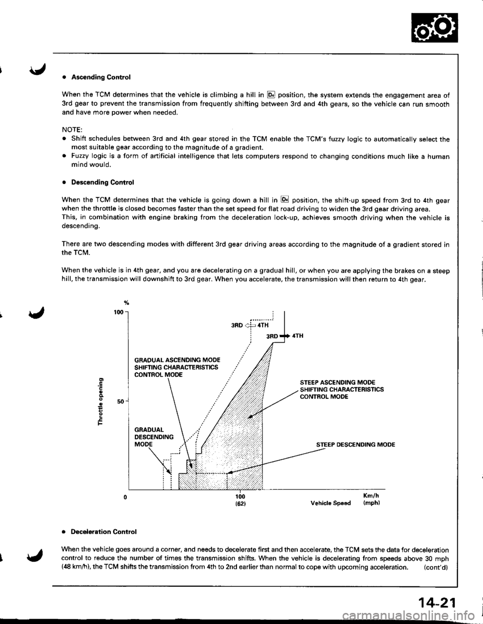
. Ascending Control
When the TCM determines that the vehicle is climbing a hill in E position, the system extends the engagement area of
3rd gear to prevent the transmission from frequently shifting between 3rd and 4th gears, so the vehicle can run smooth
and have more power when needed,
NOTE:
Shift schedules between 3rd and 4th gear stored in the TCM enable the TCM'S fuzzy logic to automatically select themost suitable gear according to the magnitude of a gradient.
Fuzzy logic is a form of artificial intelligence that lets computers respond to changing conditions much like a human
mind would,
. Descending Control
When the TCM determines that the vehicle is going down a hill in E position, the shift-up speed from 3rd to 4th gear
when the throttle is closed becomes faster than the set speed for flat road driving to widen the 3rd gear driving area.This. in combination with engine braking from the deceleration lock-up, achieves smooth driving when the vehicle is
descending,
There are two descending modes with different 3rd gear driving areas according to the magnitude of a gradient stored in
the TCM.
When the vehicle js in 4th gear, and you are decelerating on a gradual hill, or when you are applying the brakes on a steephill, the transmission will downshift to 3rd gear. When you accelerate, the transmission will then return to 4th gear,
GRAOUAL ASCENOING MOOESHIFTING CHARACTERISTICSCONTROL
STEEP DESCENDING MODE
Vehicle Speed
. Deceleraiion Control
When the vehicle goes around a corner, and needs to decelerate first and then accelerate. the TCM sets the data for deceleration
control to reduce the number of times the transmission shifts. When the vehicle is decelerating from speeds above 30 mph(,18 km/h), the TCM shifts the transmission from 4th to 2nd earlierthan normal to cope with upcoming acceleration. (cont'd)
E
F
Km/h(mph)
14-21
Page 691 of 1681
Power Steering Gearbox
Removal (cont'd)
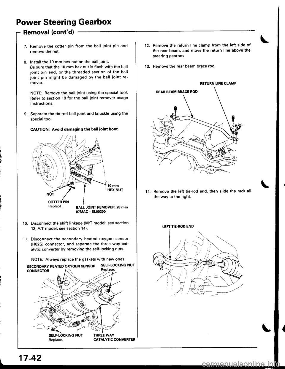
Remove the cotter pin from the ball joint pin and
remove the nut.
Install the 10 mm hex nut on the ball ioint.
Be sure that the 10 mm hex nut is flush with the ball
joint pin end, or the threaded section of the ball
joint pin might be damaged by the ball joint re-
mover.
NOTE: Remove the ball joint using the special tool.
Refer to section 18 for the ball joint remover usage
instructions.
Separate the tie-rod ball ioint and knuckle using the
special tool.
CAUTION: Avoid damaging th. ball ioint boot.
t{ePrace. BALL JOINT REMOVER,23 mm07MAC - SL0020o
10. Disconnect the shift linkage (M/T model: see section
13, A,/T model: see section 14).
11. Disconnect the secondary heated oxygen sensor
(H02Sl connector, and separate the three way cat-
alytic convener by removing the self-locking nuts.
NOTE: Always replace the gaskets with new ones.
SECONDARy HEATED OXycEN SENSOR SELF-LOCKING NUT
17 -42
Replace.CATAI.YTIC CONVERTER
12.
13.
Remove the return line clamp from the left side of
the rear beam, and move the return line above the
steering gearbox.
Remove the rear beam brace rod.
Remove the left tie-rod end. then slide the rack all
the way to the ri9ht.
14.
RETURN LINE CLAMP
LEFT NE-ROD END
Page 709 of 1681
Power Steering Gearbox
Installation (cont'dl
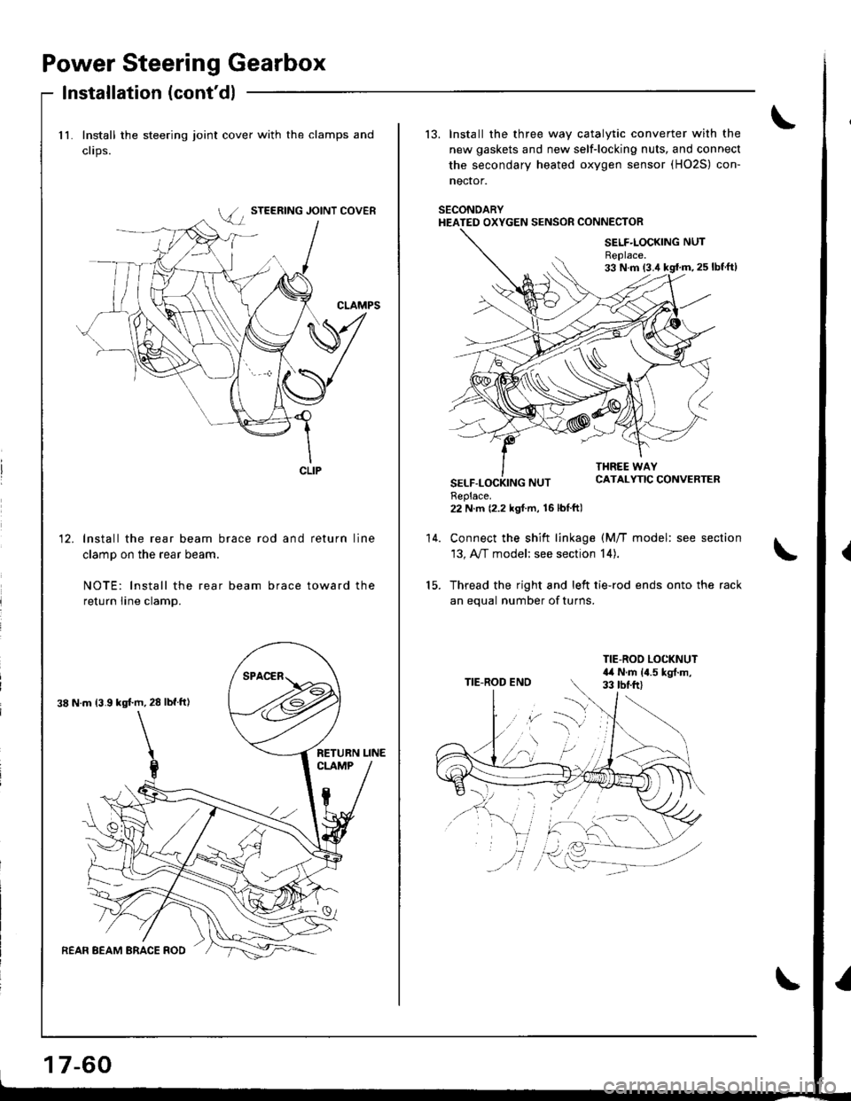
11. Install the steering joint cover with the clamps and
clips.
lnstall the rear beam brace rod and return line
clamp on the rear beam.
NOTE: lnstall the rear beam brace toward the
return line clamp.
12.
CLIP
38 N.m 13.9 kgl'm,28 lbf tl)
17-60
13. Install the three way catalytic converter with the
new gaskets and new self-locking nuts, and connect
the secondary heated oxygen sensor (HO2S) con-
nector.
SECONOARYHEATED OXYGEN SENSOR CONNECTOR
22 N.m {2.2 kgf.m, 16lbIft)
Connect the shift linkage (M/T model: see section
13, A,,/T model; see section 14).
Thread the right and left tie-rod ends onto the rack
an equal number of turns.
14.
Page 733 of 1681
Disassembly/lnspection
Inspection
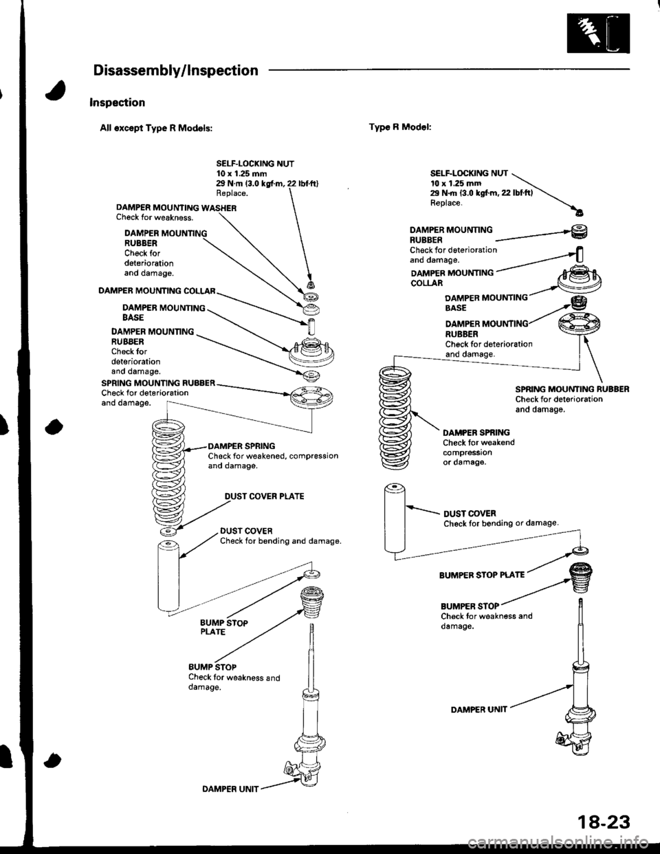
All oxcspt Type R Models:
Replace.
DAMPER MOUNTING WASHERChsck for weakn6ss.
EUMP STOPCheck tor weakness anddamage.
Type R Model:
SELF.LOCKING NUT10 x 1.25 mm29 N.rr| (3.0 kgf.m, 22 lbf.ft)SELF.LOCKING NUT \10 x 1.25 mm \29 N.rh {3.0 lgfm, 22 lbtftl \Replace. \
DAMPERRUBBERCheck fordeteriorationano oamage.
DAMPER MOUNNNGBASE
DAMPER MOUNNNGRUBBER
DAMPER MOUNTING COLLAR
DAMPER MOUNTINGRUBAERCheck fordeteriorationano oamage.
DAMPER MOUNTNGRUBBERCheckfordeteriorationano oamage,
SPRING MOUNNNG RUABERCheck for deterio.ationano oamage.
SPRING MOUNTING RUBBERCheck for detoriorationand damage.
Check for weakened, compressionand damage.
DUST COVER PLATE
DAMPEB SPRINGCheck tor weakendcompressionor damago,
Check tor weakness anddamage.
BUMPER STOP
:fftt;'"::'"''-"'"" _--4
oampea rnoun-nruc / agEcoLLAR ,_-lVDAMPERMOUNTING- Gb@
DAMP€R UNIT
DAMPER UNIT
18-23
Page 744 of 1681
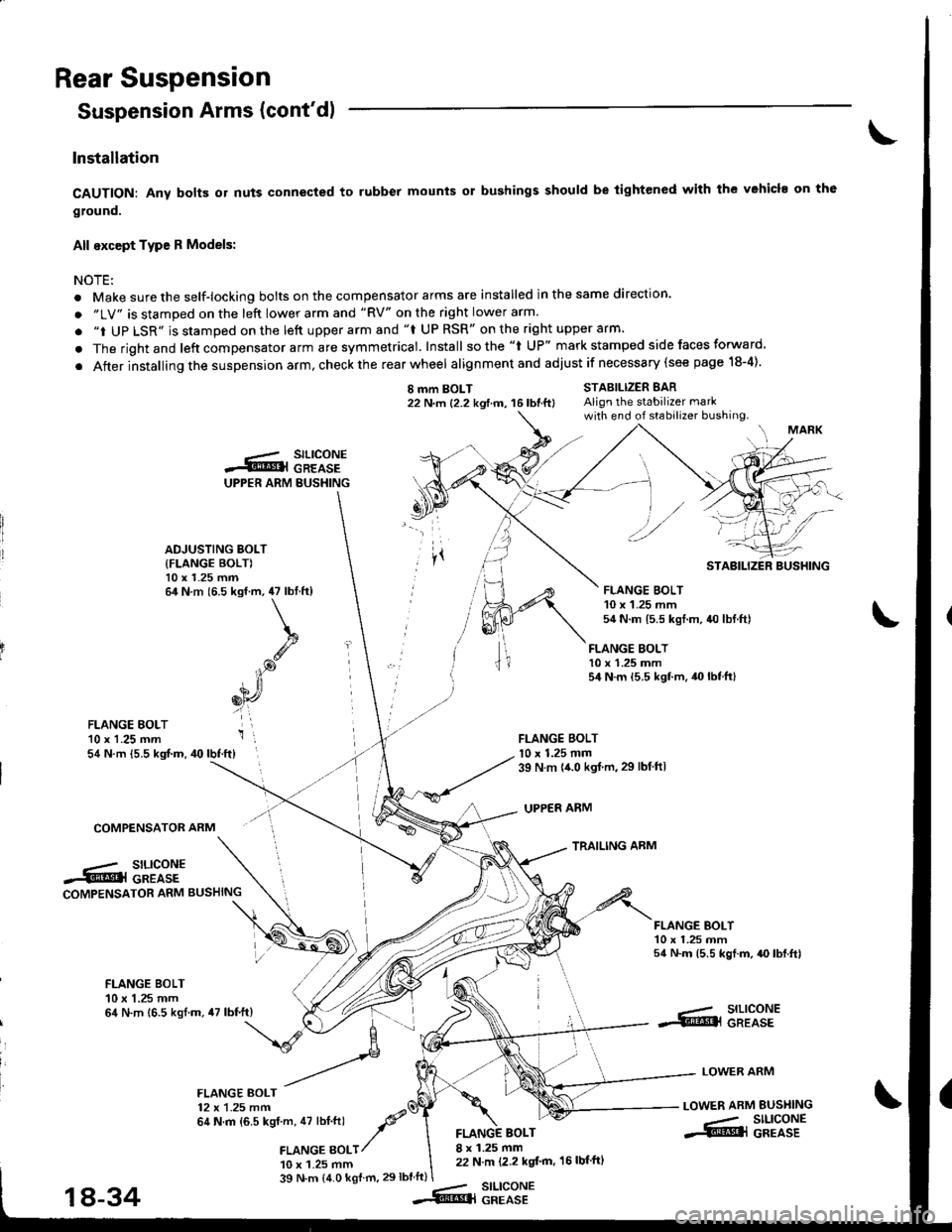
Rear Suspension
Suspension Arms (cont'dl
Installation
CAUTION: Any bolB or nuts connected to rubber mounts or bushings should be tightened with the vehicl. on th6
ground.
All except Type R Models:
NOTEi
. Make sure the self-locking bolts on the compensator arms are installed in the same direction.
. "LV" is stamped on the left lower arm and "RV" on the right lower arm.
. "i UP LSR" is stamped on the lett upper arm and "f UP RSR" on the right upper arm.
. The rightand left compensator arm are symmetrical. Install sothe "l UP" mark stamped side faces forward.
. After installing the suspension arm, check the rear wheel alignmentand adjust if necessary (see page 18-4).
I mm BOLT22 N.m {2.2 kgtm, 16lbtft}STABILIZER BARAlign the stabilizer markwith end of stabilizer bushing.
FLANGE BOLT10 x 1.25 mm54 N.m {5.5 kgf.m.40lbtft}
FLANGE BOLTl0 x 1.25 mm39 N m {{.0 kgt.m,29 lbtftl
UPPER ARM
TRAILING ARM
FLANGE EOLT'10 x 1.25 mm54 N.m {5.5 kgf.m, 40lbf.ft}
COMPENSATOR ARM
.-/ SILICONE.5tr@l GREASECOMPENSATOR ARM BUSHING
FLANGE BOI-T10 x 1.25 mm54 N.m (5.5 kgf.m, {O lbf.ft)
FLANGE BOLT10 x 1.25 mm64 N.m 16.5 kgl.m.47 lbf.ft)--- SILICONE.S!@l GREASE
LOWER ARM
LOWER ARM BUSI{ING
-- SILIGONE.S@l GREASE
FLANGE BOLT12 x 1.25 mm64 N.m {6.5 kgf m, 47 lbt.ftl -P'a
,amce gotr/
10 x 1.25 mm
BOLT8 x 1.25 mm22 N.m (2.2 kgt'm, 16 lbf'ftl
39 N.m (4.0 kgf m.29lbtft)stLtcoNEGREASE
UPPER ARM BUSHING
.-.- SILICONES@l GREASE
ADJUSTING BOLT
{FLANGE BOLT)10 x 1.25 mm64 N.m (6.5 kgf.m, 47 lbtft)
k
.g
iP
6[r,
i',
STABILIZER BUSHING
FLANGE BOLT10 x 1.25 mm54 N.m 15.5 kgt.m, 40 lbf.ftl
18-34--Rq
Page 745 of 1681
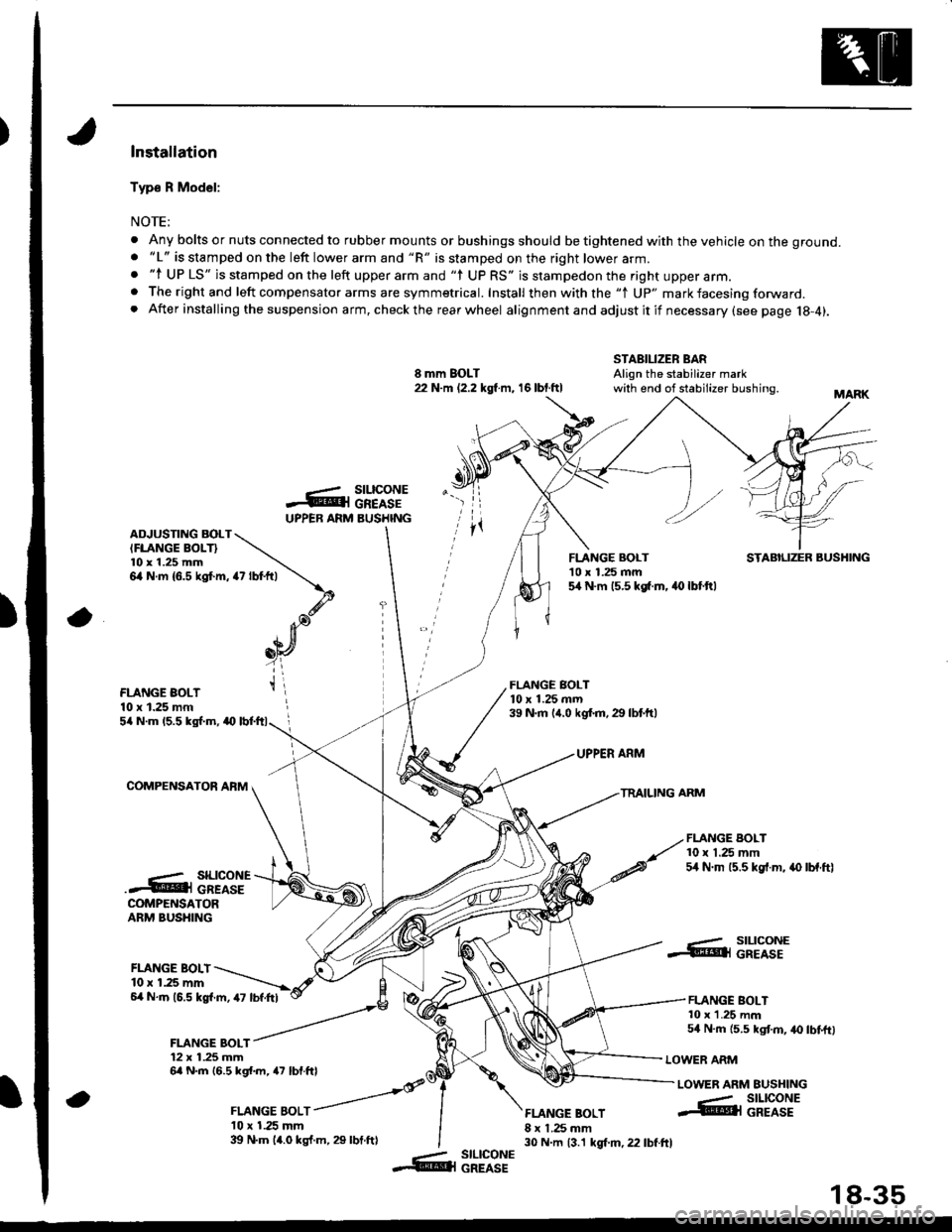
)Installation
Typ€ R Model:
NOTE;
. Any bolts or nuts connected to rubber mounts or bushings should be tightened with the vehicle on the ground.. "L" is stamped on the left lower arm and "R" is stamped on the right lower arm.. "l UP LS" is stamped on the left upper arm and "l UP RS" is stampedon the right upper arm.. The right and left compensator arms are symmetrical. Install then with the "1 Up" mark facesing forward. After installing the suspension arm, checkthe rearwheel alignmentand adjustitif necessary(see page 18-4).
8 mm BOLT22 N.m (2.2 kgl m, 16 lbt.ftl
STABILIZER BARAlign the stabilizer markwith end of stabilizer bushing.
-ArUPPEB ARM
rz tot+,t \
\.d'. Ja),n[
_oY
t\
a
stLtcoNEGREASEBUSHINGADJUSTING BOLTIFLANGE BOLT}l0 x 1.25 mm6,4 N.m {6.5 kgt m,
FLANGE BOLT'10 x 1.25 mm5,[ N.m 15.5 kg[.m. 40 lbt.ftl
STABILIZER BUSHING
FLANGE BOLT10 x 1.25 mm
FLANGE BOLT10 x 1.25 mrn39 N.m (,r.0 kgf.m.29 lbtftl5/a N.m 15.5 kgl.m, a0
COMPENSATOR AFM
UPPER ARM
TRAILING ARM
FLANGE BOLT10 x 1.25 mm54 N.m 15.5 kgf.m, .{) lbf.ftl..- SILICONE.4@i cREAsECOMPENSATORARM BUSHING
FLANGE BOLI10 r 1.25 mm6,4 N.m (6.5 kgl.m, 47 lbf.Itl
FLANGE BOLT12 x 1.25 mm6a N.m 16.5 kgl.m, a7 lbf.ftl
, ror"orr /
l0 x 1.25 mm39 N.m 14.0 kgf.m, 29 lbt.ftl
FLANGE BOLT8 x 1.25 mm30 N.m 13.1 kgt m, 22 lbf.ftl
..- SILICONE.@ll GREASE
FLANGE BOLT10 x 1.25 mm54 N.m {5.5 kgt m, 40 lbtftl
LOWER ARM
LOWER ARM EUSHING
a
--- SILICONE@l GREASE
-- slLlcoNE&l GREASE
18-35