automatic transmission HONDA INTEGRA 1998 4.G User Guide
[x] Cancel search | Manufacturer: HONDA, Model Year: 1998, Model line: INTEGRA, Model: HONDA INTEGRA 1998 4.GPages: 1681, PDF Size: 54.22 MB
Page 446 of 1681
I
I
I
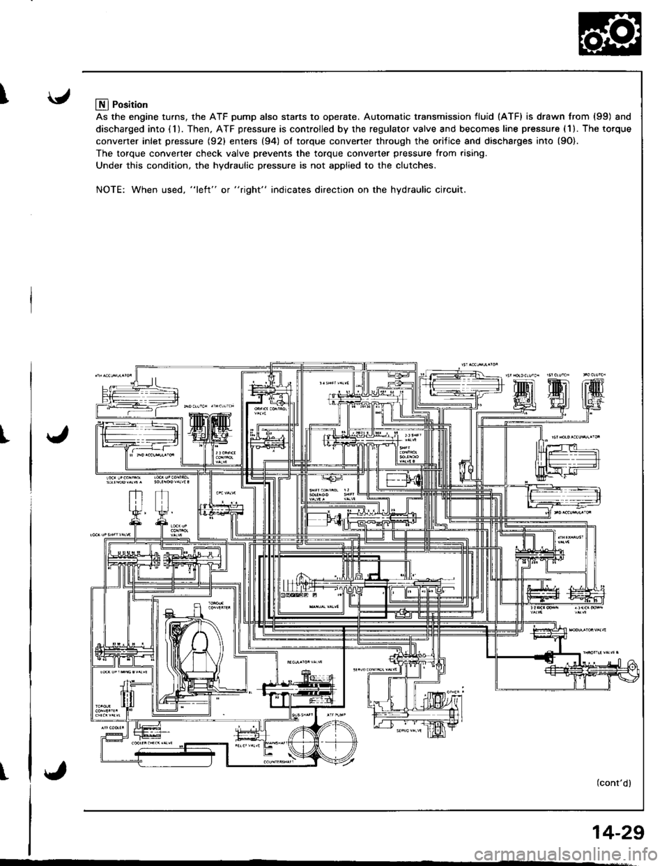
Llfl Position
As the engine turns, the ATF pump also starts to operate. Automatic transmission fluid (ATF) is drawn from (99) and
discharged into (1). Then, ATF pressure is controlled by the regulator valve and becomes line pressure (1). The torque
converter inlet pressure {92} enters (94) ol torque converter through the orilice and discharges into {9O).
The torque converter check valve prevents the torque converter pressure from rising.
Under this condition, the hydraulic pressure is not applied to the clutches.
NOTE: When used, "l€ft" or "right" indicates direction on the hydraulic circuit.
(cont'dl
14-29
Page 472 of 1681
u.drrf,,
J
J
J
14-55
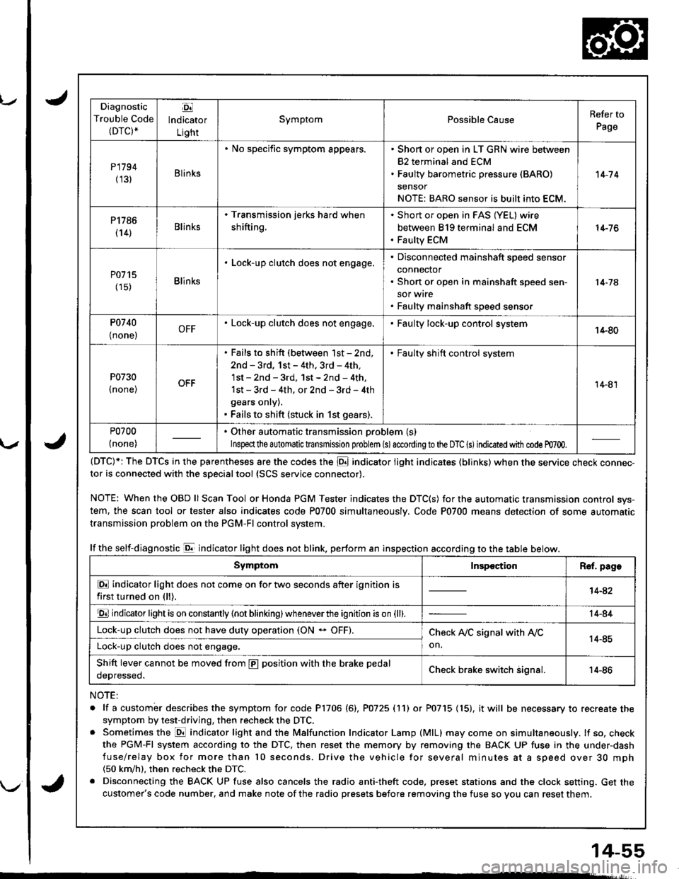
Diagnostic
Trouble Code(DTC).
Ej
lndicator
Light
SymptomPossible CauseRefer to
Page
P1794
(131Blinks
. No specific symptom appears.. Short or open in LT GRN wire between
82 terminal and ECM. Faulty barometric pressure (BARO)
sensor
NOTE: BARO sensor is built into ECM.
't 4-7 4
P1786
(14)Blinks
. Transmission jerks hard when
shifting.
Short or open in FAS (YEL) wire
between 819 terminal and ECM
Faulty ECM
14-76
P0715
(15)Blinks
. Lock-up clutch does not engage,Disconnected mainshaft speed sensor
connector
Short or open in mainshaft speed sen-
sor wrre
Faulty mainshaft speed senso.
14-74
P0740
{ none,OFF. Lock-up clutch does not engage.Faulty lock-up control system14-80
P0730
I none,
. Fails to shift (between lst - 2nd,
2nd - 3rd, 1st - 4th. 3rd - 4th,
1st - 2nd - 3rd, 1st - 2nd - 4th,
1st - 3rd - 4th, or 2nd - 3rd - 4th
gears onry).. Fails to shift (stuck in 1st gears).
. Faulty shift control system
14-81
P0700
(none)
. Other automatic transmission problem (s)
Inspeclthe a utomatic transmission problem (s)accordingto the DTC (s)indicated with code m700.
(DTC)*: The DTCS in the parentheses are the codes the E indicator light indicates (blinks) when the service cnecK connec-tor is connected with the sDecialtool {SCS service connector).
NOTE: WhentheOBDll Scan Tool orHonda PGM Tester indicates the DTC(S) for the automatic transmission control sys-
tem, the scan tool or tester also indicates code P0700 simultaneously. Code P0700 means detection of some automatic
transmission problem on the PGM-Fl control system.
lf the self-diagnostic E indicator light does not blink. perform an inspection according to the table below.
NOTE:
. lf a custombr describes the symptom for code P1706 (6), P0725 (11) or P0715 (15), it will be necessary to recreate the
symptom by test-driving, then recheck the DTC,. Sometimes the E indicator light and the Malfunction Indicator Lamp (MlL) may come on simultaneously. lf so, check
the PGM-Fl system according to the DTC, then reset the memory by removing the BACK UP fuse in the under-dash
fuse/relay box for more than l0 seconds. Drive the vehicle for several minutes at a speed over 30 mph(50 km/h). then recheck the DTC.
. Disconnecting the BACK UP fuse also cancels the radio anti-theft code, preset stations and the clock setting. Get the
customer's code number, and make note of the radio presets before removing the fuse so you can reset them.
SymptomInspectionR€f. page
E indicator light does not come on for two seconds after ignition is
first turned on (ll).14-42
E indicator light is on constantly (not blinking) wheneverthe ignition is on {ll).14-84
Lock-up clutch does not have duty operation (ON - OFF).Check A,/C signal with Ay'C
on.14-85Lock-up clutch does not engage.
Shift lever cannot be moved from E position with the brake pedal
oeDresseo.Check brake switch signal.14-86
Page 515 of 1681
Checking/Changing
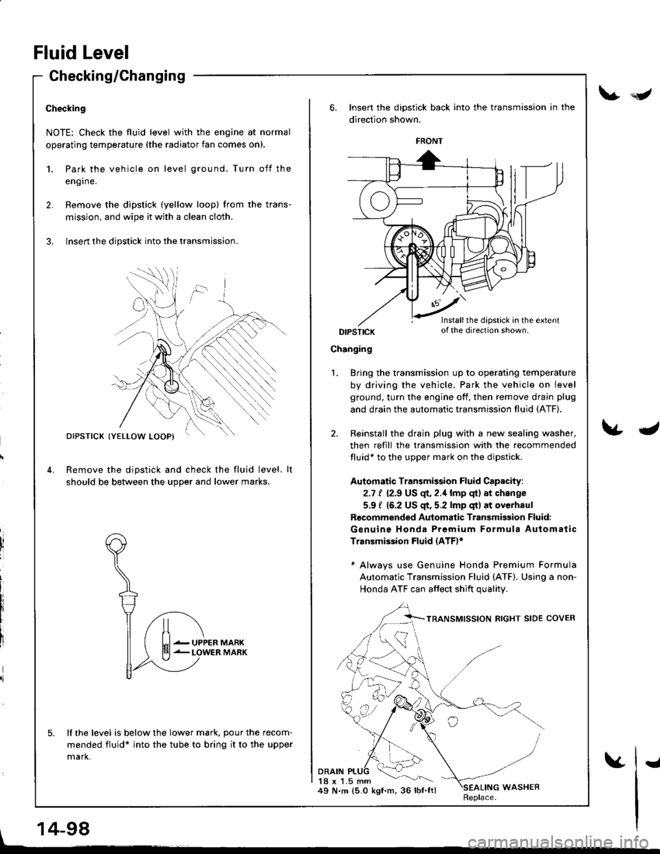
Checking
NOTE: Check the fluid level with the engine at normal
operating temperature (the radiator fan comes on).
1.
2.
Park the vehicle on level ground. Turn off the
eng I ne.
Remove the dipstick (yellow loopl from the trans-
mission, and wipe it with a clean cloth.
Insert the dipstick into the transmission.
Remove the dipstick and check the fluid level.
should be between the u9Der and lower marks.
lf the level is below the lower mark. pour the recom-
mended fluid* into the tube to bring it to the upper
mark.
DIPSTICK
UPPERLOWER
Insert the dipstick back into the transmission in the
direction shown.
DIPSTICK
Changing
DRAIN18 x 1.5 mm49 N.m 15.0 kgt.m, 36 lbf.ftl
Bring the transmission up to operating temperature
by driving the vehicle. Park the vehicle on level
ground, turn the engine off, then remove drain plug
and drain the automatic transmission fluid (ATF).
Reinstall the drain plug with a new sealing washer,
then refill the transmission with the recommended
fluid* to the upper mark on the dipstick.
Automatic Transmission Fluid Capacity:
2.7 t 12.9 US qr,2.1lmp qt) at change
5.9 / 16.2 US $. 5.2 lmp qt) at overhaul
Recommended Automatic Transmisgion Fluid:
Genuine Honda Premium Formula Automatic
Transmission Fluid (ATE*
* Always use Genuine Honda Premium Formula
Automatic Transmission Fluid (ATF). Using a non-
Honda ATF can affect shift qualitv
1.
WASHERReplace.
FRONT
Installthe dipstick in the extentof the direction shown.
Fluid Level
V*Y
\&J
, 14-98
vI
Page 522 of 1681
8.
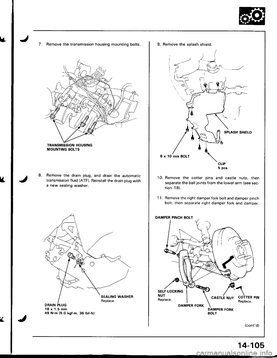
7. Remove the transmission housing mounting bolts.
Remove the drain plug, and drain the automatictransmission fluid {ATF). Reinstallthe drain plug with
a new sealing washer.
18 x 1.5 mm49 N.m {5.O kgt-m,36 lbf-fr)
V.
9. Remove the splash shield.
SPLASH SHIELD
6 x 10 mm BOLT
CLIP5 pcs.
10. Remove the cotter pins and castle nuts, then
separate the balljoints from the lower arm (see sec-
tion 18).
1 1 . Remove the right damper fork bolt and damper pinch
bolt, then separate right damper tork and damper.
PINCH BOLT
SELF.LOCKINGNUTReplace.
a
COTTER PINReplace.DAMPEB FORK
14-105
Page 598 of 1681
)
Differential
Manual Transmission
81881 engine ...................................... 15-1
818C1 engine ...................................... 15-9
818C5 engine .....,........... 15-19
Automatic Transmission .................. ..... 15-27
Page 624 of 1681
Differential (Automatic Transmission)
Speciaf Tools ........... ..........15-2A
Differential (Automatic Transmissionl
lllustrated Index .......... .. 15-29
Backlash Inspection ...... 15-30
Bearing Rep|acement ......................... I 5-30
Differential Carrier Replacement ...... l5-31
Oil SealRemoval ........... 15-32
Oil Seal Installation/
Side G|earance ................................. 1 5-32
Page 626 of 1681
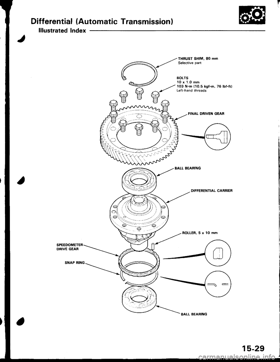
Differential (Automatic Transmission)
lllustrated Index
FINAL DRIVEI{ GEAR
BALL BEARIiIG
--tot"'
ENTIAL caRRlER
ROLLER,5xlOmm
BALL BEARING
15-29
Page 627 of 1681
Differential (Automatic Transmissionl
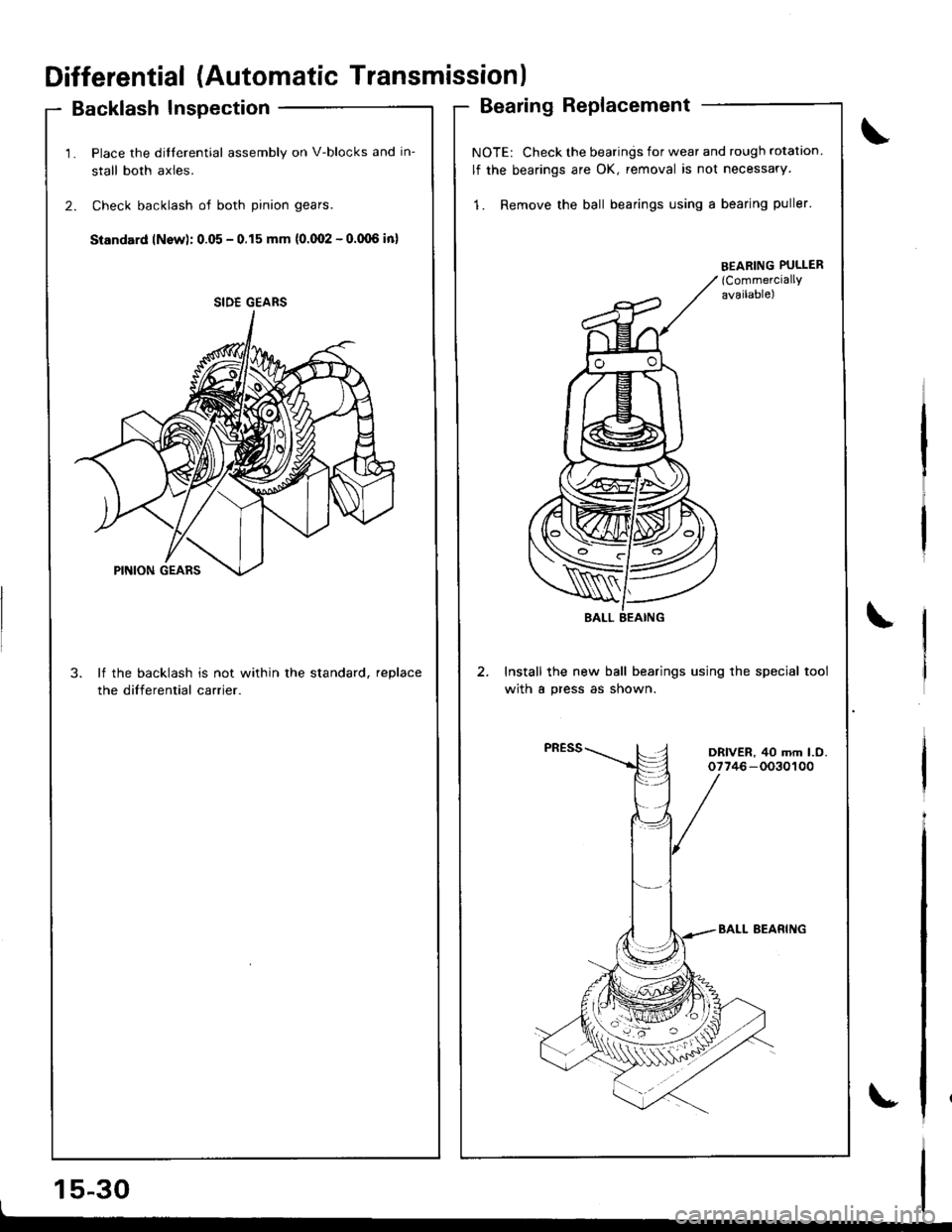
Backlash Inspection
1. Place the dilferential assembly on V-blocks and in-
stall both axles.
2. Check backlash of both pinion gears.
Standard lNsw): 0.05 - 0.15 mm {0.(Xt2 - o.(Xl6 in)
3. lf the backlash is not within the standard, reDlace
the differential carrier.
15-30I
Bearing Replacement
NOTE: Check the bearings for wear and rough rotation
lf the bearings are OK, removal is not necessary.
1. Remove the ball bearings using a bearing puller'
Install the new ball bearings using the special tool
with a press as shown.
SIDE GEARS
EEABING PULLER(CommerciallY
available)
\
DRIVER, 40 mm l.O.07746-0030100
Page 629 of 1681
Differential (Automatic Transmissionl
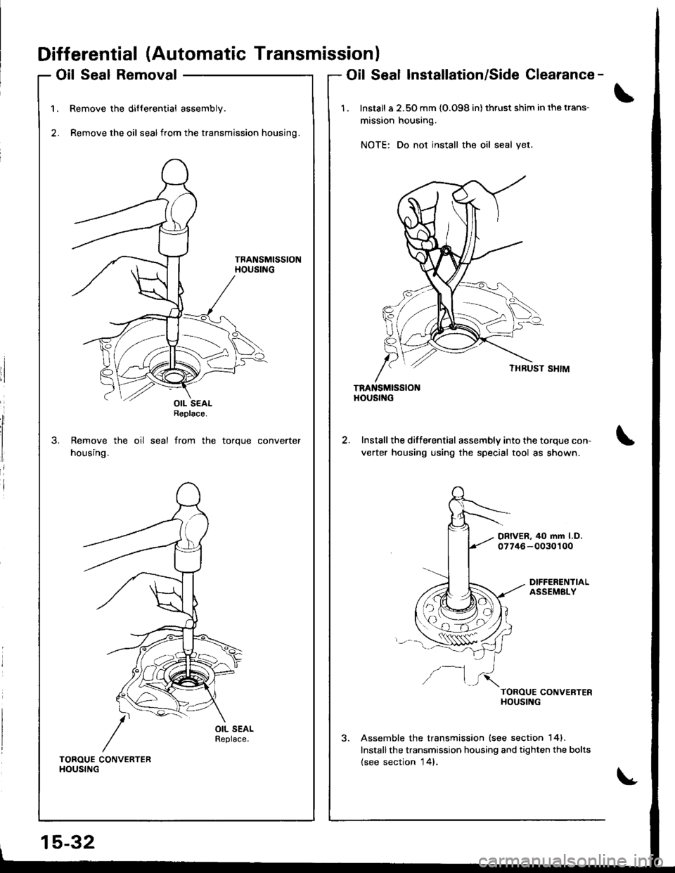
Oil Seal Removal
Remove the differential assembly.
Remove the oil sealfrom the transmission housing.
Remove the oil seal from the torque converter
housing.
Oil Seal Installation/Side Clearance-
1 . Install a 2.50 mm {O.O98 in} thrust shim in the trans-
mission housing.
NOTE: Do not install the oil seal yet.
TRANSMISSIONHOUStf{G
Install the differential assembly into the torque con-
verter housing using the special tool as shown.
DRIVER, 40 mm l.D.07746-0030100
DIFFERENTIALASSEMBLY
/--1TOROUE CONVERTERHOUSING
Assemble the transmission lsee section 141.
Installthe transmission housing and tighten the bolts(see section 14).TOROUE CONVERTERHOUSING
15-32
OIL SEALReplace.
Page 631 of 1681
Differential (Automatic Transmission)
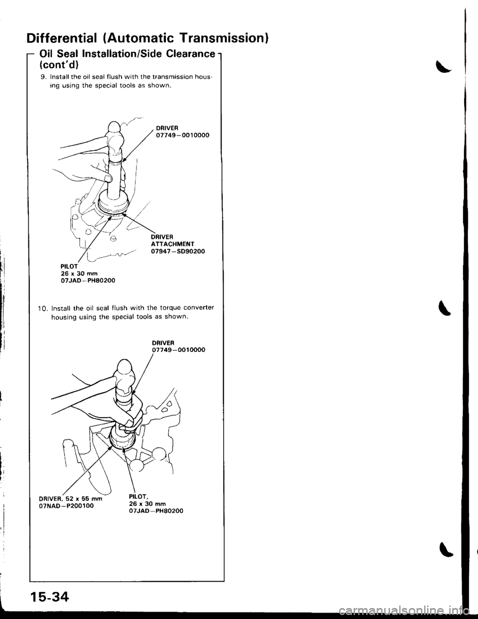
Oil Seal Installation/Side Clearance
(cont'd)
9. lnstall the oil seal llush with the transmission hous-
ing using the special tools as shown.
ATTACHMENTo7947 -SD90200
10.
PILOT26x30mmoTJAO-PHA0200
Install the oil seal llush with the torque converter
housing using the special tools as shown.
15-34