check transmission fluid HONDA INTEGRA 1998 4.G User Guide
[x] Cancel search | Manufacturer: HONDA, Model Year: 1998, Model line: INTEGRA, Model: HONDA INTEGRA 1998 4.GPages: 1681, PDF Size: 54.22 MB
Page 634 of 1681

t
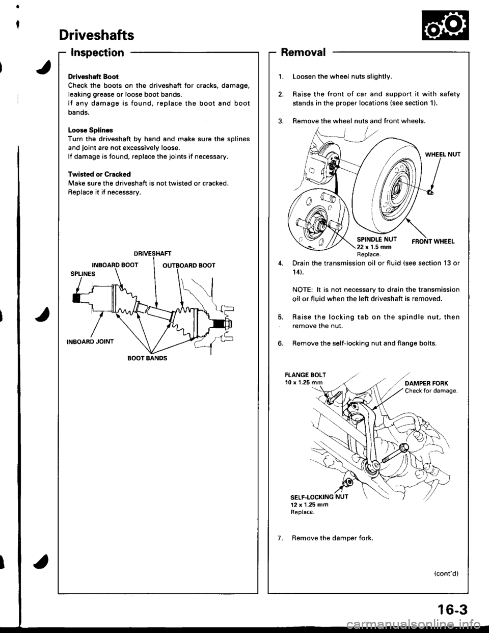
Driveshafts
Inspection
Drivcshatt Boot
Check the boots on the driveshaft tor cracks. damage,
leaking grease or loose boot bands.
lf any damage is found, replace the boot and boot
oanos.
Looso SplineE
Turn the driveshaft by hand and moke sure the splines
and joint are not excessively loose.
lf damage is found, replace the joints if necessary.
Twisled or Crscked
Make sure the driveshaft is not tlvisted or cracked.
Replace it if necessary.
BOOT BANDS
1.Loosen the wheel nuts slightly,
Raise the front of ca. and support it with safety
stands in the prope. locations {see section 1).
Remove the wheel nuts and front wheels.
5.
Drain the transmission oil or fluid (see section 13 or
14t.
NOTE: lt is not necessary to drain the transmission
oil or fluid when the left driveshaft is removed.
Raise the locking tab on the spindle nut, then
remove the nut.
6. Remove the self-locking nut and flange bolts.
FLANGE BOLT'10 x 1.25
SELF.LOCKING NUT
12 x 1.25 mmReplace.
(cont'd)
Replace.
7. Remove the damoer fork.
Removal
6-3
Page 646 of 1681

Intermediate Shaft
Removal
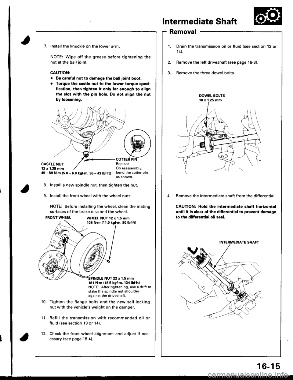
Drain the transmission oil or fluid {see section 13 or
14t.
Remove the left driveshaft (see page 16-3).
Bemove the three dowel bolts.
Remove the intermediate sh8ft from the differential.
CAUTION: Hold the intermediate shaft horizontal
until it is clear ot th6 difforantirl to prevont damage
to thc ditf€rential oil seal.
7. Install the knuckle on the lower arm.
NOTE: Wipe off the grease before tightening the
nut at the ball joint.
CAUTION:
. Be careful not to damago the ballioint boot.
. Torque the castle nut to tho low€r torque speci-
tication, then tighten it only lar onough to align
th6 slot whh tho pin hols. Do not align the nut
by loosening.
,.<__coTTEF PtNCASTLE NUT12 x 1.25 mm49 - 59 N.m {5.0 - 5.0 kgf.m, 36 - t3 lbl.ft)
Beplace.On reassembly,bend the cotter pin
8. Install a new spindle nut, then tighten the nut.
9. Installthe front wheel with the wheel nuts.
NOTE: Before installing the wheel, clean the mating
surfaces of the brake disc and the wheel.
FRONT WHEELWH€EL NUT 12 x 1.5 mm108 N.m (11.0 kgt m,80lbf ft)
10.
NUT 22 x '1.5 mm181 N m 118.5 kgl.m, 134lbtftlNOTE: After tightening, use a drift tostake the spindle nut shoulderagainst the driveshatt.
Tighten the flange bolts and the new self-locking
nut with the vehicle's weight on the damper.
Refill the transmission with recommended oil or
fluid (see section 13 or 14).
11.
12. Check the front wheel alignment and adjust if nec-
essary (see page 18-4).
INTERMCOIATE SHAFT
16-15
Page 1406 of 1681

Ground-to-Components I ndex
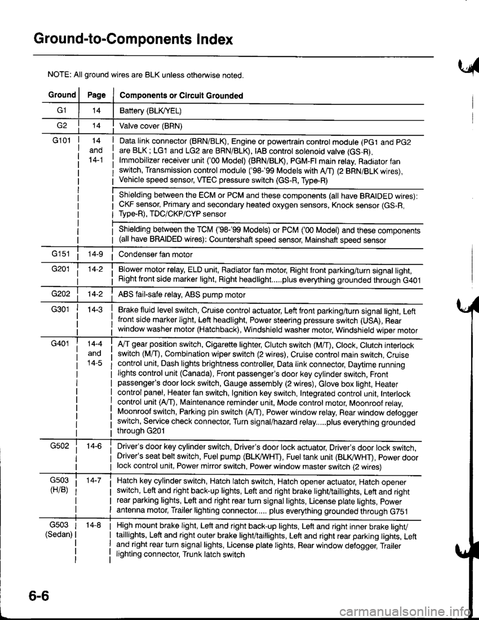
NOTE: All ground wires are BLK unless otherwise noted.
GroundPageComponents or Circuit Grounded
Battery (BLIVYEL)
--t'I Valve cover (BRN)
G101t.+
and
14-1
Daia link connector (BRN/BLK), Engine or powertrain controt module (pct and pG2
are BLK; LG1 and LG2 are BRN/BLR, IAB controt solenoid valve (GS-B),
lmmobilizer receiver unit ('00 Model) (BRN/BLR, PGM-Ft main retay, Radiator fan
switch, Transmission control module ('98.�99 Models with MD (2 BRN/BLK wires),
Vehicle speed sensor, WEC pressure switch (GS-R, Type-R)
Shielding between the ECM or PCM and these components (all have BRAIDED wires):
CKF sensor, Primary and secondary heated oxygen sensors, Knock sensor (GS-R,
Type-R), TDC/CKP/CYP sensor
Shielding between the TCM ('98-'99 Models) or PCM ('00 Model) and these components(all have BRAIDED wires): Countershaft speed sensor, Mainshaft speed sensor
G1s1 ii Condenser fan motor
Brake fluid level switch, Cruise control actuator, Left front parking/turn signal light, Left
front side marker light, Left headlight, Power steering pressure switch (USA), Rear
window washer motor (Hatchback), Windshield washer motor, Windshield wiper motor
14-3
Blower motor relay, ELD unit, Badiator fan motor, Right front parking/turn signal light,
Right front side marker light, Right headlight.....plus everything grounded through G401
ABS fail-safe relay, ABS pump motor
G40114-4
ano
l4-c
A,/T gear position switch, Cigarette lighter, Clutch switch (M,/T), Ctock, Ctutch interlock
switch (MfD, Combination wiper switch (2 wires), Cruise control main switch, Cruise
control unit, Dash lights brightness controller, Data link connector, Daytime running
lights control unit (Canada), Front passenger's door key cylinder switch, Frontpassenger's door lock switch, Gauge assembly (2 wires), Glove box light, Heater
control panel, Heater tan switch, lgnition key switch, Integrated control unit, Interlock
control unit (AfI), Maintenance reminder unit, Mode control motor, Moonroof relay,
Moonroof switch, Parking pin switch (AfD, Power window relay, Rear window defogger
switch, Service check connector, Turn signal/hazard relay.....plus everything grounded
throuoh G201
Driver's door key cylinder switch, Driver's door lock actuator, Drivels door lock switch,Driver's seat belt switch, Fuel pump (BLI(/WHT), Fuel tank unit (BLI(/WHT), power doorlock control unit, Power mirror switch, Power window master switch (2 wires)
Hatch key cylinder switch, Hatch latch switch, Hatch opener actuator, Hatch ooener
switch, Left and right back-up lights, Left and right brake light/taillights, Lett and right
rear parking lights, Left and right rear turn signal lights, License plate lights, power
antenna motor, Trailer lighting connector..... plus everything grounded through G751
6-6
'14-8G503
(Sedan)
High mount brake light, Left and right back-up lights, Lett and right inner brake tighv
taillights, Left and right outer brake light/taittights, Left and right rear parking tights, Leftand right rear turn signal lights, License plate lights, Rear window detogger, Trailer
lighting connector, Trunk latch switch
Page 1651 of 1681

I
Automatic TransmissionSection 14
\.,
'
Unit of length: mm (in)- r;rEGl,l(tll I +
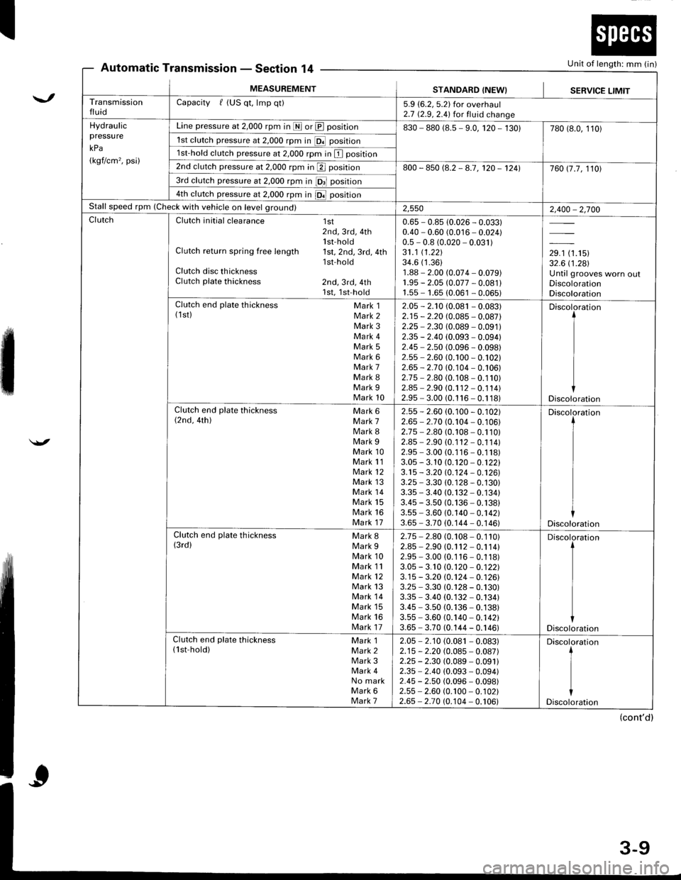
MEASUREMENTSTANDARD {NEW}SERVICE LIMITTransmissionfluidCapacity f (US qt, lmp qt)5.9 (6.2, 5.2) for overhaul2.7 (2.9,2.4) for fluid changeHydraulicpressu re
kPa
(kgf/cm'�, psi)
Line pressure at 2,000 rpm in I or @ position830 - 880 (8.5 - 9.0, 120 - 130)780 (8.0, 110)
1st clutch pressure at 2,000 rpm in [Of position
1st-hold clutch pressure at 2,000 rpm in I position
2nd clutch pressure at 2,000 rpm in p position800 - 850 (8.2 - 8.7, 120 - 1241760 17.7, 1101
3rd clutch pressure at 2,000 rpm in fOrl position
4th clutch pressure at 2,000 rpm in iOl position
Stall speed rpm (Check with vehicle on level ground)2,5502,400 - 2,700ClutchClutch initial clearance 1st2nd, 3rd, 4th1 st-hol dClutch return spring free length 1st,2nd,3rd,4thlsf holdClutch disc thicknessClutch plate thickness 2nd, 3rd, 4th1st,1st-hold
0.65 - 0.85 (0.026 - 0.033)0.40 - 0.60 (0.016 - 0.024)0.5 - 0.8 (0.020 - 0.031)31.1 (1.221
34.6 (1.36)
1.88 - 2.00 (0.074 - 0.079)1.95 - 2.05 (0.077 - 0.081 l1.55 - 1.65 (0.061 - 0.065)
,r, tr.'tur32.6 i'1.281Until grooves worn oulDiscolorationDiscolorationClutch end plate thickness Mark 1(1st) Mark 2Mark 3Mark 4Mark 5Mark 6Mark 7Mark 8Mark 9Mark 10
2.05 - 2.'t0 (0.081 - 0.083)2.15 - 2.20 (0.085 - 0.087)2.25 - 2.30 (0.089 - 0.091)2.35 - 2.40 (0.093 - 0.094)2.45 - 2.50 (0.096 - 0.098)2.55 - 2.60 (0.100 - 0.102)2.65 - 2-70 (0.104 - 0.106)2.75 - 2.80 (0.108 - 0.110)2.45 - 2.90 (0.1 12 - 0.1 14)2.95 - 3.00 (0.1 16 - 0.1 18)
Discoloration
Discoloration
Clutch end plate thickness Mark 6(2nd, 4th) Mark 7Mark 8Mark 9Mark 10Mark 11Mark 12Mark 13Mark 14Mark 15Mark 16Mark 17
2.55 -2.60 (0.100 - 0.102)2.65 - 2.7 0 (0.104 - 0. 1 06)2.75 - 2.80 (0.108 - 0.110)2.85 - 2.90 (0. 1 12 - 0.1 1 4)2.95 - 3.00 (0.1 16 - 0.1 18)3.05 - 3. 10 (0.120 - 0.12213.15 - 3.20 10.124 - 0.12613.25 - 3.30 (0. 1 28 - 0.130)3.35 * 3.40 (0.132 - 0.134)3.45 - 3.50 (0.136 - 0.138)3.55 - 3.60 (0.140 - 0.142)3.65 - 3.70 (0.144 - 0.146)
Discoloration
Discoloration
Clutch end plate thickness Mark g(3rd) Mark 9Mark 10Mark 11Mark 12Mark 13Mark 14Mark 15Mark 16Mark 17
2.75 - 2.80 (0.108 - 0.110)2.85 - 2.90 (0.1 12 - 0.1 14)2.95 - 3.00 (0.116 - 0.118)3.05 - 3.10 (0.120 - 0.12213.15 - 3.20 @j24 - 0.12613.25 - 3.30 (0.128 - 0.130)3.35 - 3.40 (0. 132 - 0.134)3.45 - 3.50 (0.136 - 0.138)3.55 - 3.60 (0.140 - 0.142)3.65 - 3.70 (0.144 - 0.146)
Discoloration
Discoloration
Clutch end plate thickness Mark 1(lst-hold) Mark 2Mark 3Mark 4No markMark 6Mark 7
2.05 - 2.10 (0.081 - 0.083)2.15 - 2.20 (0.085 - 0.087)2.25 - 2.30 (0.089 - 0.09112.35 - 2.40 (0.093 - 0.094)2.45 - 2.50 (0.096 - 0.098)2.55 - 2.60 (0.100 - 0. 1 02)2.65 - 2.70 (0.104 - 0.106)
Discoloration
t
I
iDiscoloration
(cont'd)