ignition HONDA INTEGRA 1998 4.G Workshop Manual
[x] Cancel search | Manufacturer: HONDA, Model Year: 1998, Model line: INTEGRA, Model: HONDA INTEGRA 1998 4.GPages: 1681, PDF Size: 54.22 MB
Page 1556 of 1681
![HONDA INTEGRA 1998 4.G Workshop Manual lnterlock System
- 98-99 Models
l
HxPS*. !Til;;----
-i yxRi*I DASH I / rulE rz I HOOD
i[EiF,, i]!orn.o" Bli;;1il ilEjii
!s?T"., Lt::-s::3L j "3T",,. P,vu,d Lg _ _ Lt av ^rra: 8Y C216 16I wx HONDA INTEGRA 1998 4.G Workshop Manual lnterlock System
- 98-99 Models
l
HxPS*. !Til;;----
-i yxRi*I DASH I / rulE rz I HOOD
i[EiF,, i]!orn.o" Bli;;1il ilEjii
!s?T"., Lt::-s::3L j "3T",,. P,vu,d Lg _ _ Lt av ^rra: 8Y C216 16I wx](/img/13/6069/w960_6069-1555.png)
lnterlock System
- '98-'99 Models
'l
HxPS*. !'Til;;----
-''i yxRi*I DASH I / rulE rz I HOOD
i[EiF,, i]!orn.'o" Bli;;1il ilEjii
!s?T"., Lt::-s::3L j "'3T",,. P,v'u,d Lg _ _ Lt av ^rra: 8Y C216 16I wxlcnr,r PHora 24
J!^_YEUBLI
UNOER.OASHFUSE/RELAYBOX
c440
c432
ll S€o Power Diskibution,I page 10-9.
,n"tto"" I
1c,u'"" 11 | sa31F-I''I BRAKE SWITCH T--1 THROTTLE
I I closed wrth brake | 5"ns6, I lg.qLrlgN fiP)
lq-]J 1"""",i:;*""* t iii*' i "s'H39*
:ilH1fti$;",,"
;lX *Tt r#i*f= ft;1uii,'" 11? I ;:: [S[l 5p,[,"f*,,*""*l
;ny,t;sfl E?[T
l-T;l'"
t, L- t''""t'1"' ---C "0.,, to"-t' I
STEEBINGLOCK
r-=KeyInlerlockSwitchClosed withkey pushsd.
KeylnterlockSolenold
'" I--j"$t'U"t--:t "o', 3*".''
'f 'o"
i
-
r-, gEr-
- - -;;; - - - -: t rmrsu tsstot't ll
L$'e: 1ui ifiin?rri!::::
I
:- - _ _ _ _::{ : _ _ _ _ _ _ __ - - - J "",.
-JWHT]"TEL
INTERLOCKCONTROLUNIT
;,-".t^-l[-
-------;;f[ ":'"'"."'
seeA/rGearr A c+sg ar< Posnon
wHr BL( [ ero'o i28 cn1,,rvxr ll Indicalor
r* "o"* rz | g+r.q -,
l,/ |Bi*:yJL,tx o"nf'$y:-----1a"r.EAR
I G-11 sh,ft rever push ! | "- i a.o, I P/,oSlTloN swlTcH
-il,tii,oJ,tu"o.""""0 | ^ll \, | -'
-iJcni.'
!"L-----. i, !
'g",J"T,F;:'A$l"Y"";%,r, i" ---1 'r a solenord flom enelgrTing
"'^l '";;'"-
R:":.Rt?i# i F 33""'?Ji"" i ::f;',3J3u:"00":"":Ji",",",a-< 3l'Jlilgl L___+_::':_j ;;ff;;;;rr"p,".."dBLK I NOTE: In case olBLK I NOTE: In case ot syslem
Y r ! ccro malfunchon lhesh1fllever
I ",, I paoro to can be released byI --' I oushino the ionition kev
J---r"?r-"*l-f----) Distribution,
I oaoe to-o.
I ruse aa flNTERLocK uNrn( r.5^
i.- - ---- -
Koy Int6rlockCircuitAllows key inlerlocksolenoid to boenergized unlessshift lever is in "P'
138
f __ --__l pushing lhe ignition key
,lt--- il'""J1:oi:'""i,:"0'"d'l-' c4ol
Page 1557 of 1681

- '00 Model
I
I
FUsg 52I56€ Pow€r Ilxrtdhxbn, :g9:t"t:.i
UNDER.HOODFUSEiRELAYBOXPHOfO 21
Sse Power I DASHDlslribution, : FUSE/page 1G8. I RELAY
c440
c432
WHT/GFNSTEERINGLOCK
rry Ihtsdock :Suhch IClos€d with Il(ey pusned. I
I
I
I
I
I
I
c432
It
I
I
l-
WrtT/BLU
WHT/BLU
KryIr$rdockSdanold
c412-l SHIFT
, I LOCKI I SOLENOIDI lcuoto tzo
Jc412
c414
rAc4
m2Y c4
INtl
.-, I
i/BLX U
-rl"o
POWERTRAINCONTROLMODULE(PCM)
YEVBLX
INTERLOCKCONTROLUNIT
"-*;.'l[-
- - - - - - - -;*f-tr "'"'"'"-,,
r I casr a4
""""#"J;:.
_^ ll"ij*sa*,"
l4J $l't'"ii,''F:^,
*"T't. 3il1;'
;fi;ifJ,t""**o
i"'f- .
*1'
S€e A,/T GsarPositionlndicator
"liiffo,,' a"-BLK I 506 Grourd I-i-. ;*'o' ---;
*"1
I "l! s'*l'"-
Prevents shift locksolenoid trom energizingunless brake pedal isdepressed and acceleratorpedal is not depressed.
NOTE| In case of systemmalfunction, the shilt levercan be released bypushing the ignition keyinto the release slot nearthe shift lever
$l;---l UiSi'"
BRAKE SWITCH F--.t THROTTLE
;'3i:g*s::: !.mnj iffibr-
*,
,V-I'c4ol: PHoro s6
138-1
Page 1558 of 1681

lnterlock System
- How the Circuit Works
Key Interlock
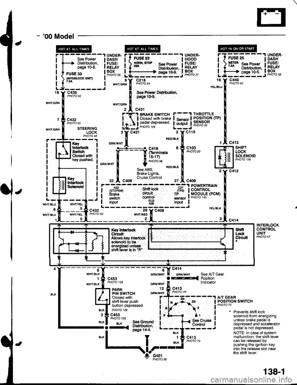
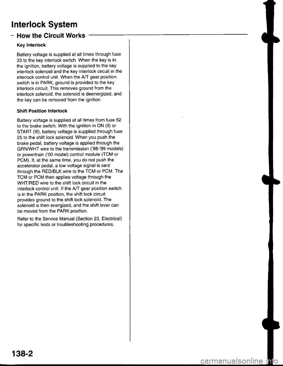
Battery voltage is supplied at all times through f use
33 to the key interlock switch. When the key is in
the ignition, battery voltage is supplied to the key
intedock solenoid and the key interlock circuit in the
interlock control unit. When the A/T gear position
switch is in PABK, ground is provided to the key
interlock circuit. This removes ground from the
interlock solenoid, the solenoid is deenergized, and
the key can be removed from the ignition.
Shift Position Interlock
Battery voltage is supplied at all times lrom fuse 52
to the brake switch. With the ignition in ON (ll) or
START (lll), battery voltage is supplied through luse
25 to the shift lock solenoid. When you push the
brake pedal, battery voltage is applied through the
GRN/VVHT wire to the transmission ('98-�99 models)
or powertrain ('00 model) control module (TCM or
PCM). lf, at the same time, you do not push the
accelerator pedal, a low voltage signal is sent
through the RED/BLK wire to the TCM or PCM. The
TCM or PCM then applies voltage through the
WHT/RED wire to the shift lock circuit in the
interlock control unit. lf the A,/T gear position switch
is in the PARK position, the shift lock circuit
provides ground to the shift lock solenoid. The
solenoid is then energized, and the shift lever can
be moved from the PARK Dosition.
Refer to the Service Manual (Section 23, Electrical)
for specific tests or troubleshooting procedures.
138-2
Page 1561 of 1681

Power Mirrors
- How the Gircuit Works
The two outside mirrors are controlled by the power
minor switch. Each mirror has two reversible
motors: one motor moves the mirror uo and down
and the other motor moves the mirror left and right.
The oower mirror switch contains three switches lo
control mirror direction, and two switches to select
the left or right mirror. With the ignition in ON (ll),
battery voltage is supplied to the power mirror
switch. The mirror selector switch directs voltage
from two of the direction switches to either the left
or the right minor. Each direction switch is used for
more than one function.
Mirror Up Operation
With the power mirror switch in the up position,
switch 1 is moved to the A oosition. Switch 1
applies battery voltage to both the left and right
power mirror up/down motors. lf the mirror selector
switch is in the left position, the left up/down motor
is grounded through the mirror selector switch and
switch 2 in the B position to G501 (Sedan) or G502
(Hatchback). lf the right mirror up/down motor is
selected il is also grounded through switch 2 in the
B position.
Mirror Down Operation
With the power mirror switch in the down position,
switches 2 and 3 are moved to the A position.
Switch 2 applies battery voltage to the left or right
power mirror up/down motor as determined by the
mirror selector switch. The selected mirror motor is
grounded through switch I in the B position to G501
(Sedan) or G502 (Hatchback). When switch 2 is
moved to position A, it also applies battery voltage
to the selected mirror lefyright motor. With switch 3
in the A position, battery voltage is supplied to both
sides of the leruright motor so it does not move.
Mirror Left Operation
With the power mirror switch in the left position,
switches 1 and ? ate moved to the A oosition.
Switch 2 applies battery voltage to the left or right
power mirror lefvright motor as determined by the
mirror selector switch. The selected mirror motor is
grounded through switch 3 in the B position to G501
(Sedan) or G502 (Hatchback). When switch 2 is
moved to position A, it also applies battery voltage
to the selected mirror up/down molor. With switch 1
in the A position, battery voltage is supplied to both
sides of the uD/down motor so it does not move.
Mirror Right Operation
With the power mirror switch in the right position,
switch 3 is moved to the A position. Switch 3
applies battery voltage through the mirror selector
switch to the left or right lefvright motor. The
motor is grounded through the mirror selector
switch and switch 2 in the B oosition to G501
(Sedan) or G502 (Hatchback).
Refer to the Service Manual (Section 23, Electrical)
for specific tests or troubleshooting procedures.
141-2