ignition HONDA INTEGRA 1998 4.G Workshop Manual
[x] Cancel search | Manufacturer: HONDA, Model Year: 1998, Model line: INTEGRA, Model: HONDA INTEGRA 1998 4.GPages: 1681, PDF Size: 54.22 MB
Page 1361 of 1681
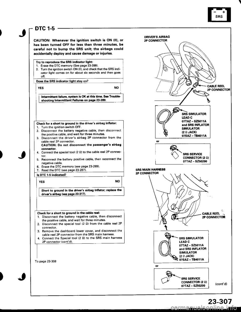
DTC 1-5
CAUTION: Whenever thc ignition switch i3 ON (lll, ot
has been turned OFF for less than throe minutss, bo
caretul not to bump the SRS unit; the airbsgs could
accidcntally deploy and cause damage or iniuri6.
DRIVER'S AIRBAG2P CONNECTOR
\"o""'"o'
CABI.E REEL
{cont'd}
)SRS SERVICECoNNECTOR 12 0)07TA2 - S250200
';
CABLEREEL.,2P OONNECTOF
)
ol
SRS SERVICECoNNECTOR (2 0l
07TAZ - SZSo2(xt
Try to ..produco the SRS indicator light:1. Erase the DTC memory (See page 23-289).2. Torn the ignition switch ON (ll), and chockrhattho SRS indi-cator light comes on for about six seconds and then goes
off.
Ooes ihe SRS indicator lighl slay on?
rffit
i .hooting ldt.rnittont Frilul.. on p.g. 23-289. I
Chock to. a 3hort to glound in tho drivor's airbag inflato.:
1. Turn the ignition switch OFF.2. Disconnect the battery nggative cable, then disconnect
the oositive cable, and wait forth.oe minutes.
3. Disconnect the driver's airbag 2P connoctor from the
cable reel 2P connector.CAUTION: Do not disconnsct tha pt!3onga]'t rirbrg
connoctor.4. Connect the special tool (2 0) to tho cable reel 2P connec_
tor,5. Reconnect tho battery positive cablo, then reconnoct the
negativ€ cable.6. Erase the DTC memory (see page 23-289)
7. Read the DTC (see pag623-2871.
k DTC 1-5 indicated?
YESNO
Sho.t to gtound in tha drive/s ri6ag infi.tor; ruplaco tho
drivor'3 .irbss (s.o p.g€ 23-3171.
Ch.ck tor a 3ho.t to gtound in tha cable ?ral:
1. Disconnect the battery negative cable. then disconnect
the oositive cable, and wait for three minutes.
2. oisconnect the special tool (2 0) lrom the cable reel 2P
connector,3. Remove the dashboard low€r cove., and disconnecl thg
cable reel 2P connector lrom the SRS main harn6ss,1. Connect the Special tool (2 0) to the SRS main harness
2P connoctor lcont'd).
To page 23-308
07TAZ - SZ50t1A.nd SRS INFLATORSIMULATOR{2 0 JACK}07SAZ - TB/OI lA
SRS SIMULATORLEAD C07TAZ - SZ501rAand SRS INFLATORSIMULATOR(2 0 JACKI07SM - TBi|t}l1A
23-307
Page 1363 of 1681
)
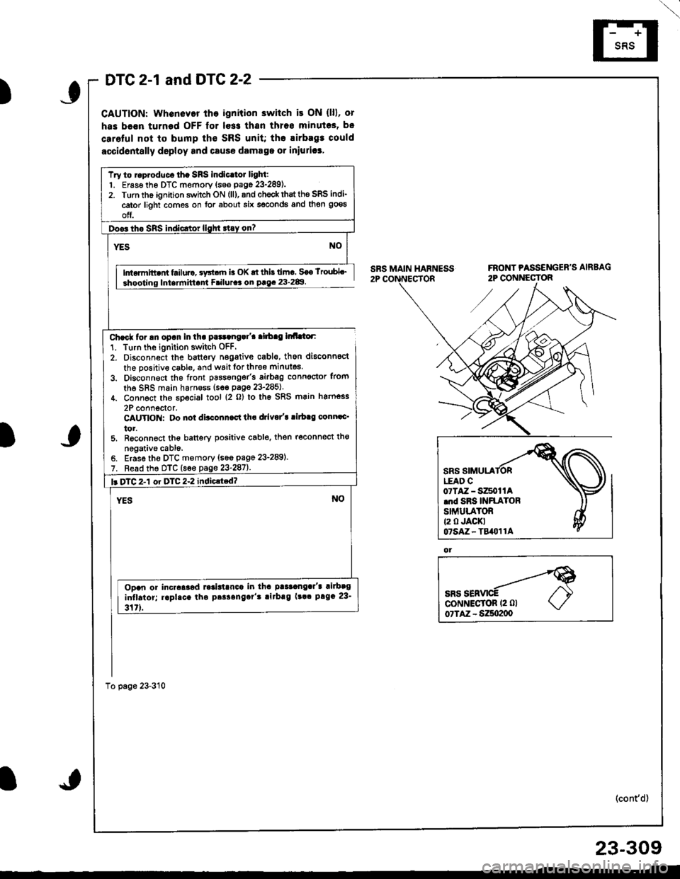
DTC 2-1 and DTG 2-2
CAUTION: whenevor tho ignition switch it ON (lll, or
has bc€n turnod OFF lor le$ thsn thros minutos, b.
carolul not to bump th€ SRS unit; the airbagt could
accidontslly deploy and csuse damsga or iniurica,
lntormitt nt failurc, sy3t.rn b OK rt this lima Saa lroubL_
Iniarmittant Friluraa on paq. 23-2&l
Char* for an opan in tha pataangal'a alrbag lr Llor:
1. Turn the ignition switch OFF.
2. Oisconnect the bauery n6gative cabl€, then di6conn6ct
the positive cable, and wait lor thr€o minutes.
3. Disconnect the front passonger's airbsg conn€ctor trom
the SRS main harness (s6€ paoe 23'285).
4. Connect th6 sDecial tool {2 o} lo th6 SRS main hatnoss
2P connoctor.CAUYIO : Oo not ditconn.ct th. drivo/t ritb.g conn.c'
tor.5. R6conned the banery positive cablo. then r6connect tho
negative cabl6.Erase tho DTC memory {s6o page 23-289).
Read the DTC (see page 23-287).
Try to raproduc. th. SRS indicltot light:1. Er6s6 th6 DTC memory {seo page 23-289).2. Turn the ignition swhch ON (ll), and ch€ck thst the SRS indi-
cator light comes on for about six seconds and then goeg
off.
l. DTC 2-1 or DTC 2-2 indiclted?
Ooan or incraaaod ].3ialrnca in tha paaaangar'a rilbag
intlaior; raphca tha paaaangar't !irbag (!a. prga 23-
317).
ot
(cont'd)
23-309
Page 1365 of 1681
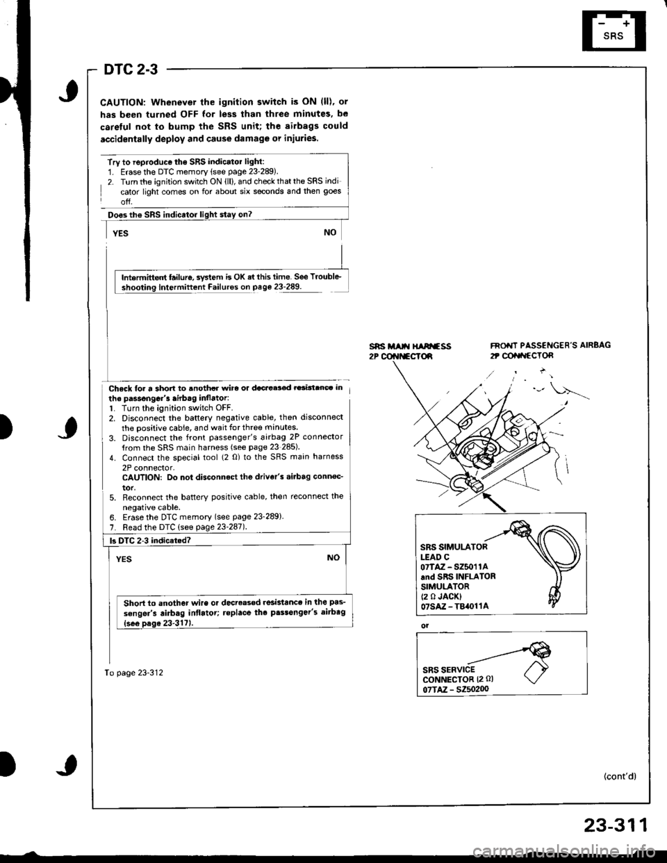
DTC 2-3
CAUTION: Whenever the ignition switch is ON (ll), or
has been turned OFF for less than three minutes, be
careful not to bump the SRS unit; the airbags could
accidentally deploy and cause damage or injuries.
Try to reproduce the SRS indicatol light:1. Erase the DTC memory (see page 23-289).
2. Turn the ignition switch ON (ll), and check that the SRS indi
cator light comes on for about six seconds and then goes
off.
Doos th€ SRS indicator
Chsck loa a short to anothcr wirc or dacacelod rarinanc. in
the passongGr'3 airb.g inflator:1. Turn the ignition switch OFF.2. Disconnect the baftery negative cable, then disconnect
the positive cable, and wait for three manutes
3. Disconnect the front passenger's 6irbag 2P connector
{rom the SRS main harness (see page 23 285)
4. Connect the special tool (2 0) to the SRS main harness
2P connector,CAUTION: Do not disconnect the drive/s .i.bag conn€c_
tor,5. Reconnect the batterY positive cable, then reconnect the
neoative cable.
s*i M t{ HIArfss2P @r{t*cTd
FNO'IT PASSENGER'S AIRBAG
2t @tat{ccTon
)
lntermittent failur€, svstem is OK ai this time. See Troubl6-
Intermittent Failures on page 23-289.
6. Erase the DTC memory (see page 23-289)
7. Read the DTC (see page 23'247l.
To page 23-312
|3 DTC 2-3 indicat.d?
Short to another wire or decreased resislance in the pas-
sengsr's airbag intlatot; teplace the p.$onger's aitbag
SRS SIMULATORLEAD C07TAZ - SZ50'r 1Aand SRS INFLATORSIMULATOR(2 0 JACK)07sAz-T84011A
ol
23-311
Page 1367 of 1681
\
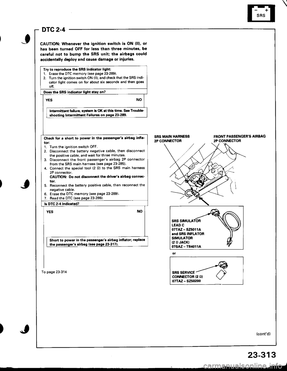
DTC 2-4
CAUTION: Whenevor th6 ignition switch is ON (ll), or
has been turned OFF for less than threo minutcs, be
car€ful not to bump lhe SRS unit; the airbEgs could
accidontslly dcploy and cause damag€ 01 iniuries.
SRS MAIN HABNESS2P CONNECTORFRONT PASSENGER'S AIRBAG
2P CONNECTOR
ot
SBS SERVICEcoNNECTOR {2 0l07TAZ - SZ5o200
(cont'd)
23-313
_-t
)
Try to roproduce th. SRS indicrtor lighl:1. Erase the DTC memory (see page 23-289).2. Turn the ignition switch ON (ll), and chock that the SRS indi-
cator light comes on for about six seconds and then goes
off.
Do.3 th. SRS indicator lighi stay on?
NOYES
Ini.rmitt.nt t iluro, !y*em b OK .t thb timo. Soe Ttoubl+,
shooting lmormittent Failuraa on P.ge 23.289
Ch6ck tor a 3hon to powol in tha pa3tonga/t lirbag infla_
to.:1. Turn the ignition switch OFF.2. Disconnect the battory negative cable, then disconnect
the oositive cable, and wait tor three manutes
3. Disconnect the front passenger's airbag 2P conn€ctorIrom the SRS main harnoss (see page 23-285).
4. Connect the soecial tool (2 0) to the SRS main harness
2P connector.CAUTION: Do not dilconn.ct tho driv.l'! .irb.g conn.c'
tor.5. Reconnect the battery positive cable, then reconnoct the
negative cable.6. Erase the DTC memory (see page 23-289).7. Read the DTC (see page 23-2861.
b DTC 2-4 indicatcd?
YESNO
Short to powor in th. pa$anoar'3 airbrg infldtor; tepl&t
the Dass6nqor'3 .irbaq {sco prgc 23-3171
To page 23-314
07TAZ-SZ50t1A.nd SRS INFLATORSIMULA'OR(2 0 JACKT07sAz - TB()11A
Page 1368 of 1681
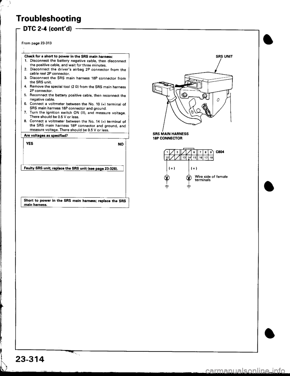
Troubleshooting
DTC 2-'l (cont'd)
From pago 23-313
Chack for e short to power in tho SRS mrin ham.3s:1. Disconnect the battery negative csble, then disconnectthe positive cable, and wait for three minutes.2. Disconnect the driver's airbag 2P connector trom thecable roel 2P connector.3. Disconnect the SnS main harness 18P connector fromthe SRS unir.4. Remove th€ special tool (2 O) from the SRS main harness2P connector.5. Reconnect the batt6ry positive cable, then reconnect thenegative cable.6. Connect a voltfieter between the No. 10 (+) terminal ofSFS main harness 18P conn6ctor and ground.7. Turn th6 ignition switch ON {ll), and measure vottage.There should be 0.5 V or less.8. Connect a voltmeter betwoen the No. 14 (+) terminal olthe SRS main harness 18P connector and ground, andmeasurethere should be 0.5 V or less.
SRS UNIT
SRS MAIN HARNESS'8P CONNECTOR
Short to power in the SRS m.in harn.G; r6pl.c. th. SFSmain h!]nca3.
23-314
Page 1369 of 1681
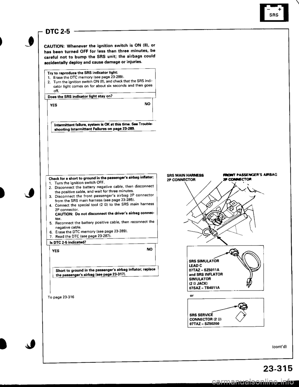
DTC 2-5
CAUTION: Whenever the ignition switch is ON (lll. ot
has been turned OFF lor less than thlee minules. be
careful not to bump the SRS unit; th€ airbags could
accidentally deploy and cause damage 01 injuri€s.
lnta.mittor tailure, aFtcrn b OK st ihb ti.rF. Sa. Tto.tbl''_
Intermittont FriluJor on pag€ 2&289.
SRS MAIN HARNESA2P CONNECTORml tlssfrliaFs AnSaG
)
u---
or
SRS SERVICECoNNECTOR {2 0lo?TM - 5250200
(cont'd)
Try to roproduce tho SRS indic.tor light:
1. Erase the DTC memory (see page 23-289).
2. Turn the ignition sv/itch ON (ll). and check that the SRS indi-
cator light comes on for about six seconds and then goes
off.
Doo6 tho SRS indic.tor light stay on?
Chgck tor a short to ground in the Pa*t€ngd'3 tirbag inflttor:
1. Tlrn the ignition switch OFF
2. Disconnect the battery negative cable, then disconnect
the oositive cable. and wait for thr€6 minutes
3. Dis;onnect the front passenger's airbag 2P connector
from the SRS main harness (see page 23-285)'
4. Connoct the special tool (2 o) to the SRS main harness
2P connector.CAUTION: Do not disconngd tho drivo"s airbtg connoc'
tor.5. Reconnect the battery positive cable' then reconnect the
negalive cable.
6. Eras6 the DTC memory (see page 23-289)'
7. Fead the DTC {see page 23'287l'.
Short to ground in tho pts.range/s airbag inflator; rsplac€
tho Da3sonse/3 si.bag (sao
23-315
Page 1373 of 1681
I
I
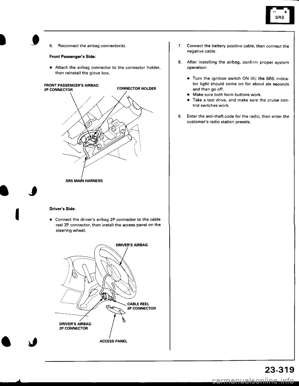
6. Reconnect the airbag connector(s).
Front Passenger's Side:
. Attach the airbag connector to the connector holder.
then reinstallthe glove box.
CONNECTOR HOLDER
Driver's Side:
. Connect the driver's airbag 2P connector to the cable
reel 2P connector, then rnstall the access panel on the
steering wheel.
\,
23-319
7.Connect the baftery positive cable, then connect thenegative cable.
After installing the airbag, confirm proper system
operal|on:
. Turn the ignition switch ON (ll); the SRS indica-
tor light should come on for about six seconds
and then go off.
. Make sure both horn buttons work.
. Take a test drive, and make sure the cruise con-
trol switches work.
Enter the anti-theft code for the radio. then enter the
customer's radio station presets,
9.
Page 1379 of 1681
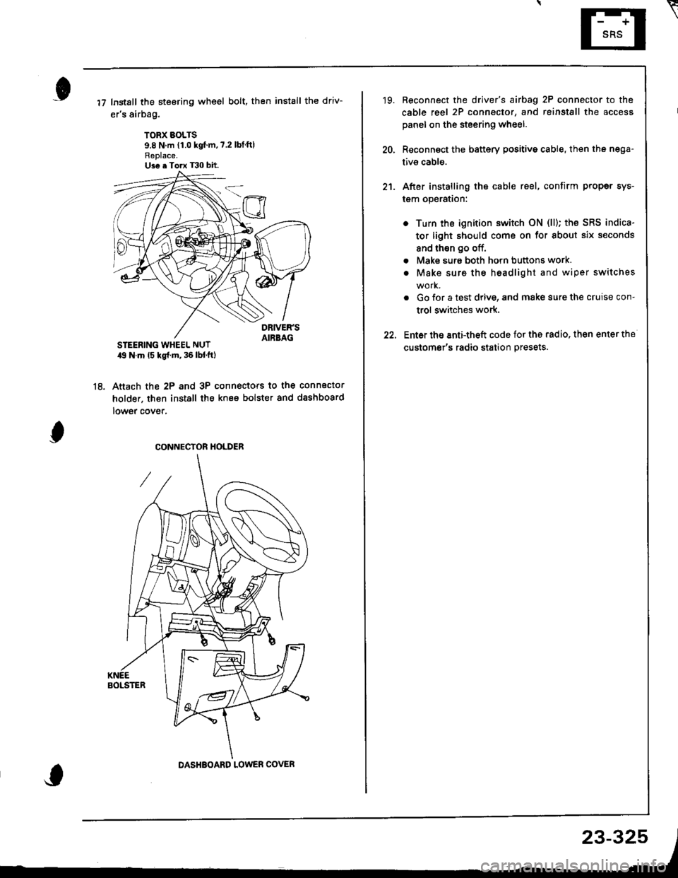
Instsll the steering wheel bolt, then install the driv-
er's airbag.
TORX BOLTS9.8 N m {1.0 kgf'm,7.2 lbtftlReplace.U3e . Torx T30 bit.
STEERING WHEEL NUT19 N.m (5 kgl.m, 36 lbl.ftl
Anach the 2P and 3P connectors to the connector
holder. then install the knee bolster and dashboard
lowgr cover,
le
CONNECTOR HOLDER
DASHBOARD LOWER COVER
23-325
\
'19. Reconnect the driver's aibag 2P connector to the
cable reel 2P connector, and reinstSll the access
panel on the steering wheel.
20, Reconnect the battery positive cable, then the nega-
tivs cable.
21. After installing the cable reel, confirm proper sys-
tgm operation:
Turn the ignition switch ON (ll); the SRS indica-
tor light should come on for about six seconds
and thsn go off.
Make surs both horn buttons work.
Make sure the headlight and wiper switches
Go {or a test drive, and make sure the cruise con-
trol switches work.
Ent6r the anti-theft code for tho radio, then enter the
customsr's radio station presets.
a
a
Page 1381 of 1681
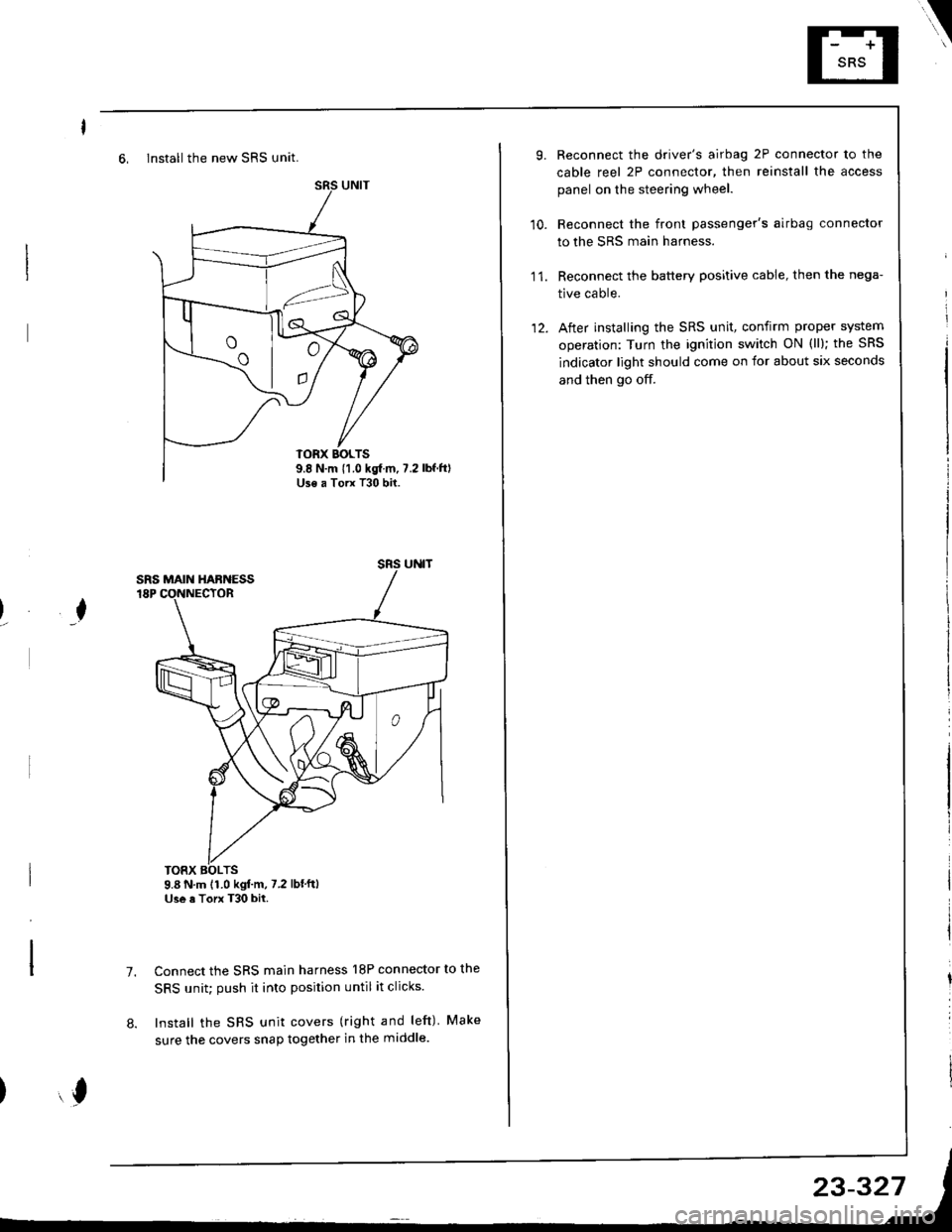
6, Install the new SRS unit.
o^ l- o
9.8 N.m 11.0 kgf m, 7.2Use a Torx T30 bit.
I
TORX BOLTS9.8 N.m 11.0 kgl.m, 7.2 lbf'ftlUse a Torx T30 bit.
7.Connect the SRS main harness l8P connector to the
SRS unit; push it into position until it clicks.
Install the SRS unit covers (right and left) Make
sure the covers snap together in the middle.8.
,l
\
10.
Reconnect the driver's airbag 2P connector to the
cable reel 2P connector, then reinstall the access
panel on the steering wheel.
Reconnect the front passenger's airbag connector
to the SRS main harness.
Reconnect the battery positive cable, then the nega-
tive cable.
After installing the SRS unit, confirm proper system
operation: Turn the ignition switch ON (ll); the SRS
indicator light should come on for about six seconds
and then go off.
11.
12.
Page 1385 of 1681
How To Use This Manual
Circuit Schematics
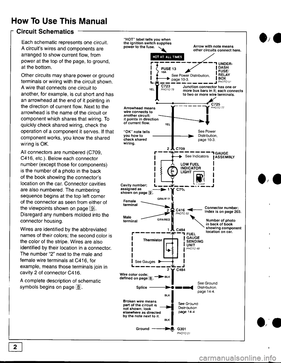
Each schematic reoresents one circuit.
A circuit's wires and components are
arranged to show current flow, from
power at the top of the page, to ground,
at the bottom.
Other circuits may share power or ground
terminals or wiring with the circuit shown.
A wire that connects one circuit to
another, lor example, is cut short and has
an arrowhead at the end of it pointing in
the direction of current flow. Next to the
arrowhead is the name ol the circuit or
component which shares that wiring. To
quickly check shared wiring, check the
operation of a component it serves. lf that
component works, you know the shared
wiring is OK.
All connectors are numbered (C709,
C416, etc.). Below each connector
number (except those for components)
is the number of a ohoto in the back
of the book showing the connector's
location on the car. Connector cavities
are also numbered. The numbering
sequence begins at the top left corner
of the connector as seen from eilher of
the viewpoints shown on page E.
Disregard any numbers molded into the
connector housing.
Wires are identif ied by the abbreviated
names of their colors; the second color is
the color of the stripe. Wires are also
identif ied by their location in a connector.
The number "2" next to the male and
female wire terminals at C416, for
example, means those terminals join in
cavity 2 of connector C41 6.
A complete description of schematic
symbols begins on page @.
O,e
Arowhead meanswire connects toanother ciacuit;it points in directionof current tlow.
"OK" note tellsYou how tocheck sharedwiring.
"HOT" label tells you whenthe ignition switch suppliesDower lo the fuse. \\
.---#
"*l
Broken wi.e means I
ffir"i:'ffi:[:l''" -{
elsewhere as directed Ioy ttt" not" n"n to [. u.* f
Ground ---{
Arrow with note meansother circuits connect here.
Distribution,page 10-3.
See lndicators
I
.| GAUGE
IASSEMBLY
I
I
I
IJO,'
i"?*i,h -..--.-{[
Cavity number; L--assigned as _----> 1shown on page l9l.
Maleterminal
c70!
F,":,2 f
- i":!f $l ?:T"'i,.i,.
Number ot photoin back ot bookshowing componentlocation on car.FUELGAUGESENDINGUNIT
See GroundDistribution.page 14'4.
c484
Thermistor
See Gauges
Splice ----------)f rr(
S€e GroundDstrb(rtlonpage 14 .l
G30t
iT;
Li=
- -.I UNDER-
FUsE 13 ../ I -Dl^s!io-a-- - , iFUsESee Power Drstlbulton. I RELAYpase 1o-3. ! Po^{^ -__:_____ ___Jp"otoa
o,a