ignition HONDA INTEGRA 1998 4.G Workshop Manual
[x] Cancel search | Manufacturer: HONDA, Model Year: 1998, Model line: INTEGRA, Model: HONDA INTEGRA 1998 4.GPages: 1681, PDF Size: 54.22 MB
Page 1393 of 1681
How To Use This Manual
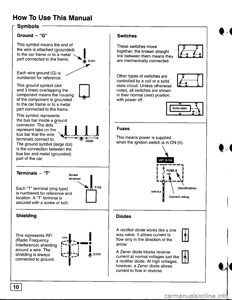
Symbols
Ground - "G"
This symbol means the end of
the wire is attached (grounded) Ito the car frame or to a metal Ipart connected to the f rame. \I orol
,
Each wire ground (G) ," -/numbered for reference.
Q,(Switches
These switches move
together; the broken straight
line between them means thev
are mechanically connected.
Other types of switches are
controlled by a coil or a solid
state circuit. Unless otherwise
noted, all switches are shown
in their normal (rest) position,
with power off .
This ground symbol (dot
and 3 lines) overlapping the
component means the housing
of the component is grounded
to the car f rame or to a metal
part connected to the f rame.
This symbol represents
the bus bar inside a ground
connector. The dots a
i"r*"""*nn"l,':" .,.L I I I
lermtnals connectto. -'--'-:t"'--------<
The ground symbol (large dot)
: Gsoo
is the connection between the
bus bar and metal (grounded)
part of the car.
Terminals - "T"
m
ffi
Solid-state
Fuses
This means power is supplied
when the ignition switch is in ON (ll).
Diodes
A rectifier diode works like a one
way valve. lt allows current to
flow only in the dlrection of the
arrow.
A Zener diode blocks reverse
currenl at normal voltages just like
a rectifier diode. At high voltages,
however, a Zener diode allows
current to flow in reverse.
Q,(
Each 'T" terminal (ring type)
is numbered for reference ano
location. A "T" terminal is
secured with a screw or bolt.
Shielding
This represents RFI
(Radio Frequency
Interf erence) shielding
around a wire. The
shielding is always
connected to ground.
,,,
n
:'iL.-!
L-_+i !",*
I
Page 1397 of 1681
How To Use This Manual
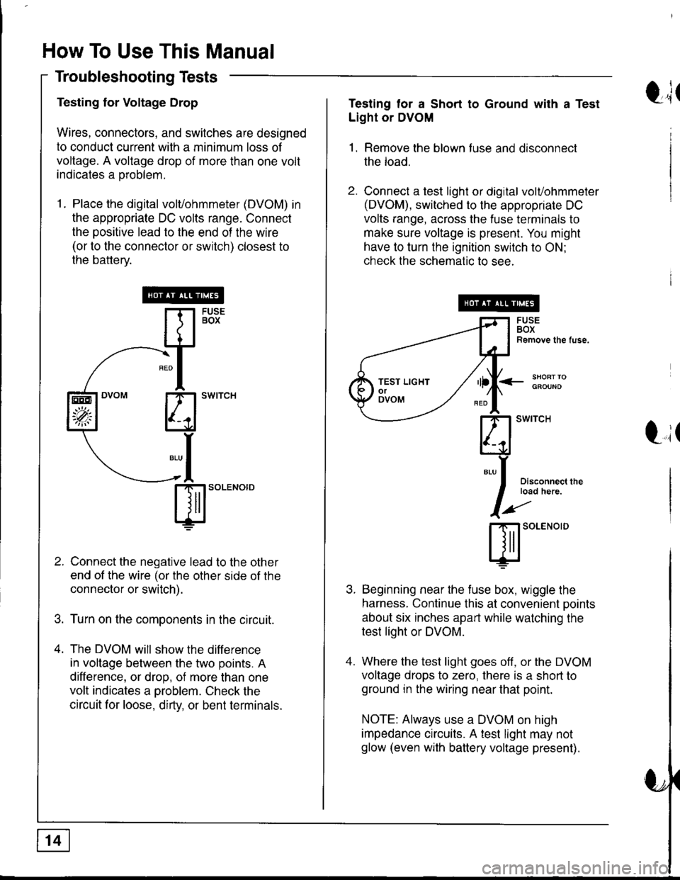
Troubleshooting Tests
Testing for Voltage Drop
Wires, connectors, and switches are designed
to conduct current with a minimum loss of
voltage. A voltage drop of more than one volt
indicates a oroblem.
1. Place the digital volvohmmeter (DVOM) in
the appropriate DC volts range. Connect
the positive lead to the end of the wire
(or to the connector or switch) closest to
the battery.
Connect the negative lead to the other
end of the wire (or the other side of the
connector or switch).
Turn on the components in the circuit.
The DVOM will show the difference
in voltage between the two points. A
difference, or drop, of more than one
volt indicates a oroblem. Check the
circuit for loose, dirty, or bent terminals.
sl'o""o'o
EEO
'p;
t;tTesting tor a Short to Ground with a Test
Light or DVOM
1. Remove the blown fuse and disconnect
the load.
2. Connect a test light or digital volvohmmeter
(DVOM), switched to the appropriate DC
volts range, across the fuse terminals to
make sure voltage is present. You might
have to turn the ignition switch to ON;
check the schematic to see.
<_SHOFTTOGFOUND
t,it
I
Disconnect theload here.
SOLENOID
Beginning near the f use box, wiggle the
harness. Continue this at convenient ooints
about six inches apart while watching the
test light or DVOM.
Where the test light goes off, or the DVOM
voltage drops to zero, there is a short to
ground in the wiring near that point.
NOTE: Always use a DVOM on high
impedance crrcuits. A test light may not
glow (even with battery voltage present).
TEST LIGHTolOVOM
Page 1400 of 1681
Fuse/Relay Information
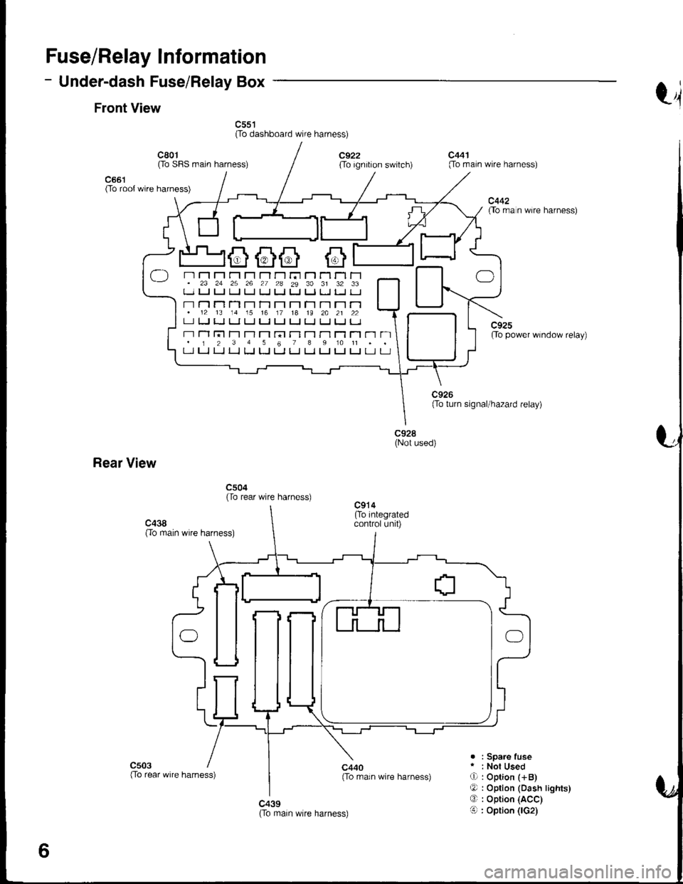
- Under-dash Fuse/Relay Box
Front Viewt4
c55't(To dashboard wire harness)
c661(To root wire harness)
c801Oo SFIS main harness)c922(To ignition switch)
c440{To rrain wire harness)
c441(To main wire harness)
c442flo rra n wire harness)
c92sOo power window relay)
c928(Not used)
Rear View
c504(To rear wire harness)
c503. : Spare fuser : Not UsedO : Option (+B)
O : Option (Dash lights)O : Option (ACC)
O : Option (lG2)c439(To main wire harness)
6
-) n Fl r"r r'r rl r-l r-r ri r'1 Tl rl r-1. 23 24 25 26 27 2a 29 30 31 32 33t_-.1 u u ! tJ LJ Ll t. Ll tJ l. tJ
- r-l n T'l T-l r't T-1 T-t r-l T-t r-l r'1.12 13 14 15 16 17 18 19 2A 21 22LI tJ LJ LI tJ I.J t-J tJ IJ IJ IJ I.J
r-r Tl l;t T'l T-l T'1 rn r-l T-t r'l T1 Tl r'1 n. 1 2 3 4 5 6 7 I 9 10 11 . .t-l LJ LJ LJ LJ [J t-t LJ Ll LJ t_l t-J Lr u
(To rear wire harness)
Page 1430 of 1681
UNDER-DASHFUSE/RELAYBOX
c301
c126
POWERTRAINor ENGINE
F,ltffi lialEE:;hfui | (PcM or EcM)
alcM) | PHaraTT lga 99)| 420 | PHA|A t4A t00i
(98 s9 20) Y (C408 98- s9)13 ll c457
YEUGFN
o
'98-'99 Models
BL{J
7
ALU
c103
cl 09
DISTRIBUTORASSEMBLY
c418(Terminals 18-20)
c452
cl27
BU'
9.
BLU
7BLU
'd
c301
JI
'"'fil
TESTr-]i.I GAUGE
lraiii'o l3,sseqarv
lmerer | --TACHOMETERCONNECTOR
IGNITIONcolLPower lgnition inputslgnalPrimaryoutout Enqine soeedcoritrol cround ouiaut (RPM)
20-.,l
Page 1452 of 1681
- How the Circuit Works
With the ignition switch in ON (ll) or START (lll),
battery voltage is supplied through fuse 15 and the
BLK//EL wire to the vehicle speed sensor (VSS).
The sensor is grounded by the BLK wire to G101.
The speedometer and other control units in the
circuit supply about 5 volts to the ORN wire. The
vehicle speed sensor (VSS) intermittently grounds
the ORN wire which generates a pulsed signal in it.
The number of pulses per minute increases/
decreases with the speed of the car
Refer to the Service Manual (Section 23, Electrical)
for specific tests or troubleshooting procedures.
33-1
Page 1457 of 1681
Cruise Control (cont'd)
- How the Circuit Works
The cruise control system uses mechanical and
electrical devices to maintain the car's soeed at a
setting selected by the driver.
System Description
The cruise control unit receives command signals
from the cruise control main switch and the cruise
control SevBesume switch. With the ignition switch
in ON (ll) or START (lll), voltage is provided to the
cruise control main switch. When you push the
switch to on, power is provided to the cruise control
unit and the brake switch.
The cruise control unit receives information about
operating conditions from the brake switch, the
ignition control module (lCM), the vehicle speed
sensor (VSS), and the clutch switch (manual
transmission) or the A,/T gear positton switch
(automatic transmission). The cruise control unit
then sends signals to the cruise conirol actuator
which regulates the throttle position to maintain the
selected speed. The control unit compares the
aclual speed of the car to the selected speed. The
control unit then uses the result of that comoarison
to oDen or close the throttle.
The brake switch releases the system's control of
the throttle at the instant you press on the brakepedal. The switch sends a signal to the control unit
by removing power from the normally closed brake
input (GRY wire), and providing power at the
normally open brake input (GRNMHT wire). The
control unit responds by allowing the throttle to
close. The clutch switch or the A/T gear position
switch sends a "disengage" signal to the control unit
that also allows the throttle to close.
The cruise control system will set and automatically
maintain any speed above 25 mph (40 km/h). To set
it, make sure the main switch is on and the switch
indicator is on. Then, after reaching the desired
speed, press the set switch. This sends a "set"
signal to the cruise control unit which, in turn,
controls the cruise control actuator to maintain the
set soeed.
When you push the SET switch and the cruise
control system is on, the "cruise control" ON
indicator lights up.
34-4
You can cancel the cruise control system by
turning the main switch off. This removes power to
the control unit and erases the set sDeed from
memory. lf the system is disengaged temporarily
by the brake switch, or clutch switch, and the car's
speed is still above 25 mph, press the RESUME
switch: the car will automatically return to the
previously set speed.
For gradual acceleration without pressing the
accelerator pedal, push the RESUME switch and
hold it there. This will send an "acceleration" signal
to the control unit. When you release the switch, the
system will be reprogrammed tor the new speed. To
slow the car down, push the SET switch in and hold
it there. This sends a "deceleration" signal to the
control unit, causing the car to coast. When the
desired speed is reached, release the SET switch.
This reprograms the system for the new speed.
Reter to the Service Manual (Section 23, Electrical)
for specific tests or troubleshooting procedures.
Page 1471 of 1681
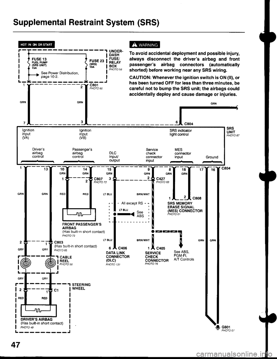
Supplemental Restraint System (SRS)
FUSE 13FUEL PUIIP(SRS UNF)t5a
FUS€ 23(s8s)
ts13t5" To avoid accidental deployment and possible iniury,
lq9Fr. always disconnect the driver's airbag and frontg[f" pas"Lnger's airbag connectors (automaticallyPHorQ 58 shorted) before working near any SRS witing.
CAUTION: Whenever the ignition switch is ON (ll), ol
has been turned OFF tor less than three minutes, be
careful not to bump the SRS unit; the airbags could
accidentally deploy and cause damage or iniuries.
{-
lgnitionrnpul(VA)
tgnitionInpul(VB)
Passenger'sarrbagcontrol
SFIS indicaiorlight control
Service MEScheck @nnectorconnector input GroundInpu
Driver'sarrbagconlr0lDLC'npuvoutput
-ro--Y---la-Y--- 16
:ffi*f:ffq
lJnor,rrpassencen= 'l t- 'i
rHas bu,ll 'n shorl contac0
I j:::T
fn'"o"t. n-n .non "on,""u
" "'Jl
"oou
""" ""]
.!, "oou $
cRN
: :3<::" :l (Y.e_er
oArA LINK sERvrcE 9qe l-qs,'l SABLE coHrecibn aH;a'i- ?9q1i iEEi- 1ot-i1 cijrlt't'ecron n/r contrors
I Pt:OfO 5a pqara t Jt PForo 76
I
STEERINGWHEEL
1
GRY
ON|vER'S AIRBAG(Has built-in short contact)
L---------J
47
GBY
r
I
I
GRY
2
NED
Page 1479 of 1681
A/C Gompressor Controls (conrd)
- How the Circuit Works
Battery voltage is supplied through fuse 56 to the
A,/C compressor clutch relay contacts at all times.
With the ignition switch in ON (ll), voltage is applied
to the coil of the A,/C compressor clutch relay
through fuse 17. When you push the A,/C switch
ON, and the heater fan switch is in posation 1, 2, 3,
or 4, a "ground" input is provided to the engine or
powertrain control module (ECM or PCM) through
the A,/C thermostat and the A,/C pressure switch.
The A,/C compressor clutch relay is grounded by the
engine or powertrain control module (ECM or PCM).
When energized, the A,/C compressor clutch relay
allows battery voltage to turn on the A,/C
comDressor clutch,
The A,/C ON indicator light comes on when the A"/C
system is requested.
A,/C Thermostat
The A,/C thermostat is located on the evaoorator
housing. The AJC thermostat turns off the A,/C
compressor clutch if the temperature at the
evaporator goes below 3'C (37'F). This prevents
condensation from freezing on the evaporator fins
and blocking the air delivery into the passenger
compartment. The blower motor will keep running
when the sensor lurns off the compressor.
A,/C Pressure Switch
The A,/C pressure switch is located in the condenser
outlet line where refrigerant is in a high
temperature/high pressure liquid state. The switch
will sense abnormally high or low pressure, and
open the circuit. This removes ground, and the
compressor will stop running.
Refer to the Service Manual (Section 22,
Air Conditioning) for specific tests or
troubleshooting procedures.
62-2
Page 1483 of 1681
Fans (cont'd)
- How the Gircuit Works
When the ignition switch is in ON (ll), voltage is
applied to the coils of the radiator fan relay and the
condenser fan relay (with A,/C) through fuse 17.
Whenever a ground is provided to the radiator fan
relay and condenser fan relay, the relays are
energized, turning on the radiator fan motor and
condenser fan motor. The relays can be grounded
by the radiator fan switch, engine or powertrain
control module (ECM or PCM) (USA), or the A,/C
and heater lan switches via the A'lC pressure switch
and the A,/C lhermostat.
A,/C Thermostat
The A,/C thermostat is located on the evaporator
housing. The A/C thermostat turns oft the A/C
compressor clutch it the temperature at the
evaporator goes below 3'C (37"F). This prevents
condensalion from freezing on the evaporator fins
and blocking the air delivery into the passenger
compartment. lt the temperature goes below 3'C
(37'F) turning off the A"/C thermostat, and the
BLU/RED wire at the A,/C diode was the only wire
providing ground to the condenser and radiator
fan relays (A,/C switch on, heater fans switch on,
radiator fan switch open, and ECM or PCM fan
controi output not grounded), the relay will
deenergize removing voltage from the condenser
and radiator fan motors causing them to stop
running.
A,/C Pressure Switch
The AJC oressure switch is located in the condenser
outlet line where refrigerant is in a high
temperature/high pressure liquid state. The A,/C
switch turns off the A,/C compressor clutch if it
senses abnormally high or low pressure. lf the A'lC
pressure switch opens, and the BLU/RED wire at
the A/C diode was the only wire providing ground
to the condenser and radiator fan relays (L/C switch
on, heater fans switch on, radiator lan switch open'
and ECM or PCM fan control output not grounded),
the relay will deenergize removing voltage from the
condenser and radiator fan motors causing them to
stop running.
A./C Diode
This diode orevents the radiator fan switch f rom
grounding the "A'lC ON" input to the engine or
powertrain control module (ECM or PCM).
Refer to the Service Manual (Section 23, Electrical)
for specific tests or troubleshooting procedures.
63-3
Page 1485 of 1681
- How the Circuit Works
Voltage is applied at all times through f use 50 to
the rear window defogger relay. With the ignition
swrtch in ON (ll), voltage is applied through luse
16 to the rear window defogger relay and the
defogger ON indicator.
When you turn the rear window defogger switch to
ON, a path to ground is provided for the rear
window defogger relay and the defogger ON
indicator through the integrated control unit. The
defogger ON indicator light comes on and the rear
window detogger relay contacts close. Voltage is
applied to the detogger grid on the surface of the
rear window and the grid heats the rear window to
remove any fog lrom the glass.
A timer in the integrated control unit will automatically
tum off the defogger atter 20 to 30 minutes.
Refer to the Service Manual (Section 23, Electrical)
for specific tests or troubleshooting procedures.
64-1