Power steering pump HONDA INTEGRA 1998 4.G Owner's Manual
[x] Cancel search | Manufacturer: HONDA, Model Year: 1998, Model line: INTEGRA, Model: HONDA INTEGRA 1998 4.GPages: 1681, PDF Size: 54.22 MB
Page 1049 of 1681

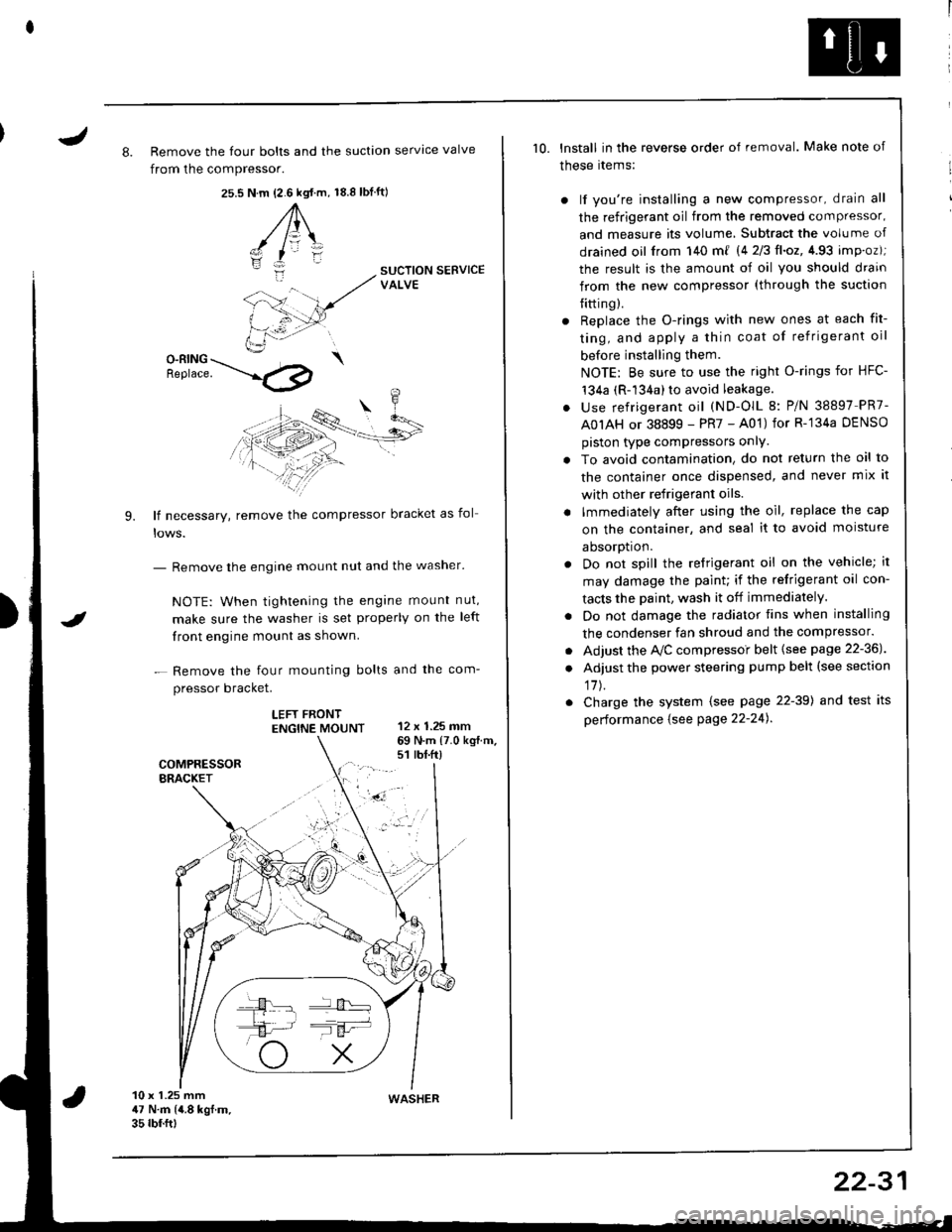
J8. Remove the four bolts and the suction servtce valve
from the compressor.
25.s18.8 tbf.ft)N.m {2.6 kgt.m,
A\
-/ l=\'zI
i:-
9.
SUCTION SERVICEVALVE
O-RING \Benrace. --'.l4p
lf necessary, remove the compressor bracket as fol
- Remove the engine mount nut and the washer'
NOTE: When tightening the engane mount nut,
make sure the washer is set properly on the left
front engine mount as shown.
- Remove the four mounting bolts and the com-
pressor bracket.
LEFT FRONTENGTNE MOUNT 12 x 1.25 mm
I
69 N.m {7.0 kg{.m.s1 rbt.ft)
10 x 1.25 mm47 N.m (4.8 kgf.m.35 rbf.ftt
10. lnstall in the reverse order of removal. Make note of
these rtems:
) lf you're installing a new compressor, drain all
the refrigerant oil from the removed compressor,
and measure its volume, Subtract the volume of
drained oil from 140 m{ 14 2/3ll.oz,4.93 imp.oz);
the result is the amount of oil you should drain
from the new compressor (through the suction
{itting).
r Replace the O-rings with new ones at each fit-
ting, and apply a thin coat of refrigerant oil
before installing them.
NOTE: Be sure to use the right O-rings for HFC-'t34a (R-134a) to avoid leakage.
. use refrigerant oil (ND-OlL 8: P/N 38897 PR7-
A0IAH or 38899 - PR7 - A01) for R-'134a DENSO
piston type compressors onlY.
. To avoid contamination, do not return the oil to
the container once dispensed, and never mix it
with other refrigerant oils.
. lmmediately after using the oil, replace the cap
on the container, and seal it to avoid moisture
aDsorDt|on.
. Do not spill the refrigerant oil on the vehicle; it
may damage the paint; if the refrigerant oil con-
tacts the Daint, wash it off immediately.
. Do not damage the radiator fins when installing
the condenser fan shroud and the compressor.
. Adjust the Ay'C compressoi belt {see page 22-36J
. Adjust the power steering pump belt (see section
17J.
. Charge the system (see page 22-39) and test its
performance {see Page 22-24).
WASHER
22-31
Page 1054 of 1681

A/C Compressor Belt
Adiustment
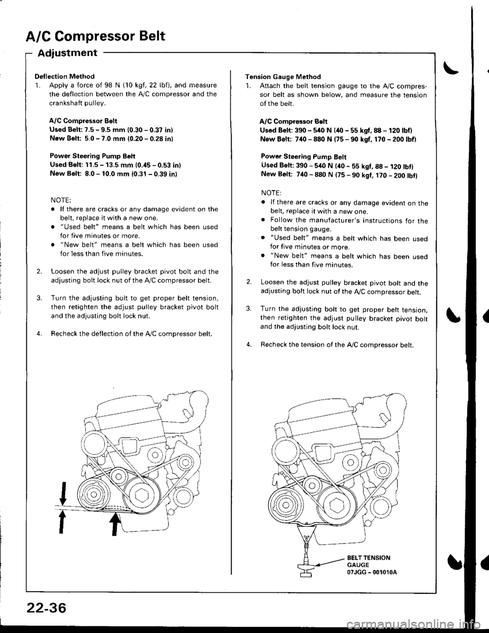
Dellection Method
1. Apply a force of 98 N i10 kgf, 22 lbf), and measure
the deflection between the A,/C compressor and the
crankshaft pullev.
A/C Compressor Belt
Used Belt: 7.5 - 9.5 mm (0.30 - 0.37 in)
New Beli: 5.0 - 7.0 mm (0.20 - 0.28 in)
Power Steering Pump Belt
Used Bslt: 11.5 - 13.5 mm (0.i15 - 0.53 in)
New Belt: 8.0 - 10.0 mm (0.31 - 0.39 in)
NOTE:
. lf there are cracks or any damage evident on the
belt, replace it with a new one.
. "Used belt" means a belt which has been used
for five minutes or more.
. "New belt" means a belt which has been used
for less than five minutes.
Loosen the adjust pulley bracket pivot bolt and the
adjusting bolt lock nut of the lVC compressor belt.
Turn the adjusting bolt to get proper belt tension,
then retighten the adjust pulley bracket pivot bolt
and the adjusting bolt lock nut.
Recheck the deflection of the Ay'C compressor belt.
22-36
Tension Gauge Method
1. Attach the belt tension gauge to the Ay'C compres-
sor belt as shown below, and measure the tension
of the belt.
A/C Comprossor Belt
Used Belt: 390 - 5/rc N (4O - 55 kgf. 88 - 120 lbf)
New Bslt: 7,10 - 880 N (75 - 90 kgf, 170 - 200 lbf)
Power Steering Pump Belt
Used Belt: 390 - 540 N (ito - 55 kgl, g8 - i20 tbtlNew Belt: 740 - 880 N (75 - 90 kgt, 170 - 200 tbtl
NOTE:
. lf there are cracks or any damage evident on thebelt, replace it with a new one.. Follow the manufacturer's instructions for thebelt tension gauge.
. "Used belt" means a belt which has been usedfor five minutes or more.. "New belt" means a belt which has been usedfor less than five minutes.
Loosen the adjust pulley bracket pivot bolt and theadjusting bolt lock nut of the A,/C compressor belt.
Turn the adjusting bolt to get proper belt tension,then retighten the adjust pulley bracket pivot boltand the adjusting bolt lock nut.
Recheck the tension of the A,/C compressor belt.
3.
BELT TENSIONGAUGE07JGG - 0010'l0a
Page 1406 of 1681

Ground-to-Components I ndex
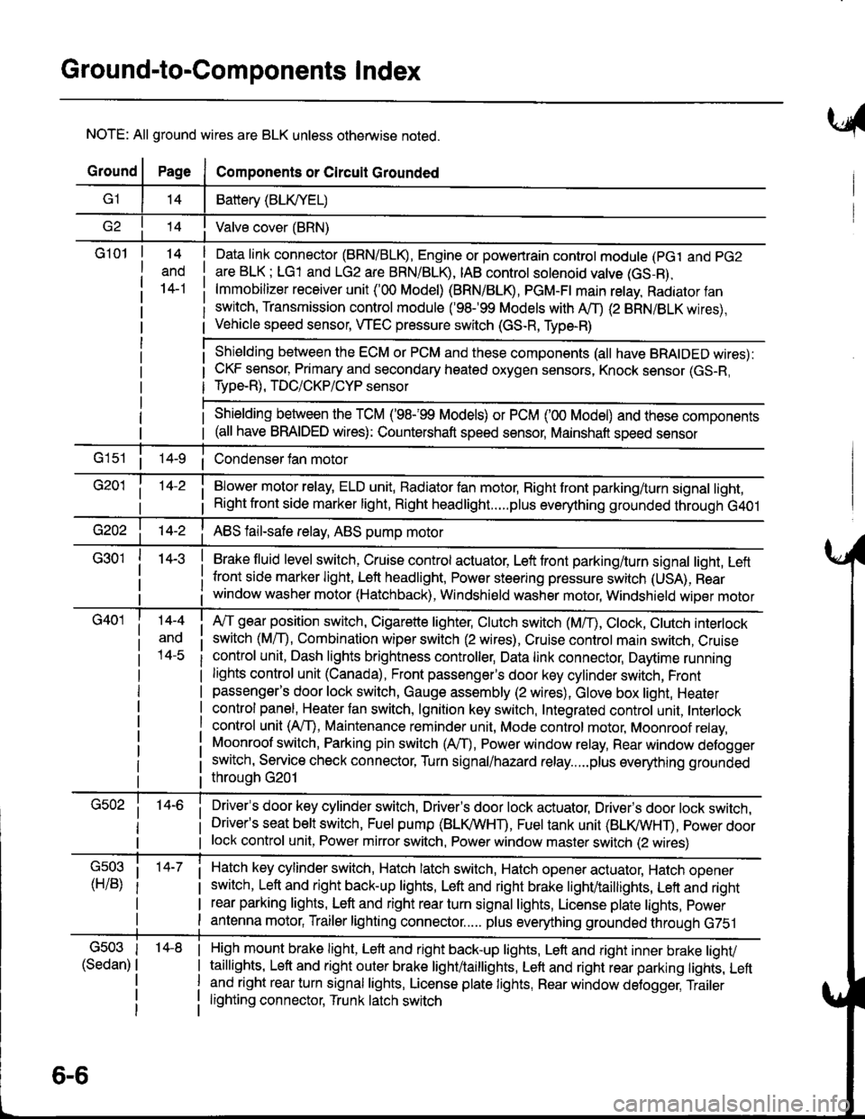
NOTE: All ground wires are BLK unless otherwise noted.
GroundPageComponents or Circuit Grounded
Battery (BLIVYEL)
--t'I Valve cover (BRN)
G101t.+
and
14-1
Daia link connector (BRN/BLK), Engine or powertrain controt module (pct and pG2
are BLK; LG1 and LG2 are BRN/BLR, IAB controt solenoid valve (GS-B),
lmmobilizer receiver unit ('00 Model) (BRN/BLR, PGM-Ft main retay, Radiator fan
switch, Transmission control module ('98.�99 Models with MD (2 BRN/BLK wires),
Vehicle speed sensor, WEC pressure switch (GS-R, Type-R)
Shielding between the ECM or PCM and these components (all have BRAIDED wires):
CKF sensor, Primary and secondary heated oxygen sensors, Knock sensor (GS-R,
Type-R), TDC/CKP/CYP sensor
Shielding between the TCM ('98-'99 Models) or PCM ('00 Model) and these components(all have BRAIDED wires): Countershaft speed sensor, Mainshaft speed sensor
G1s1 ii Condenser fan motor
Brake fluid level switch, Cruise control actuator, Left front parking/turn signal light, Left
front side marker light, Left headlight, Power steering pressure switch (USA), Rear
window washer motor (Hatchback), Windshield washer motor, Windshield wiper motor
14-3
Blower motor relay, ELD unit, Badiator fan motor, Right front parking/turn signal light,
Right front side marker light, Right headlight.....plus everything grounded through G401
ABS fail-safe relay, ABS pump motor
G40114-4
ano
l4-c
A,/T gear position switch, Cigarette lighter, Clutch switch (M,/T), Ctock, Ctutch interlock
switch (MfD, Combination wiper switch (2 wires), Cruise control main switch, Cruise
control unit, Dash lights brightness controller, Data link connector, Daytime running
lights control unit (Canada), Front passenger's door key cylinder switch, Frontpassenger's door lock switch, Gauge assembly (2 wires), Glove box light, Heater
control panel, Heater tan switch, lgnition key switch, Integrated control unit, Interlock
control unit (AfI), Maintenance reminder unit, Mode control motor, Moonroof relay,
Moonroof switch, Parking pin switch (AfD, Power window relay, Rear window defogger
switch, Service check connector, Turn signal/hazard relay.....plus everything grounded
throuoh G201
Driver's door key cylinder switch, Driver's door lock actuator, Drivels door lock switch,Driver's seat belt switch, Fuel pump (BLI(/WHT), Fuel tank unit (BLI(/WHT), power doorlock control unit, Power mirror switch, Power window master switch (2 wires)
Hatch key cylinder switch, Hatch latch switch, Hatch opener actuator, Hatch ooener
switch, Left and right back-up lights, Left and right brake light/taillights, Lett and right
rear parking lights, Left and right rear turn signal lights, License plate lights, power
antenna motor, Trailer lighting connector..... plus everything grounded through G751
6-6
'14-8G503
(Sedan)
High mount brake light, Left and right back-up lights, Lett and right inner brake tighv
taillights, Left and right outer brake light/taittights, Left and right rear parking tights, Leftand right rear turn signal lights, License plate lights, Rear window detogger, Trailer
lighting connector, Trunk latch switch
Page 1655 of 1681

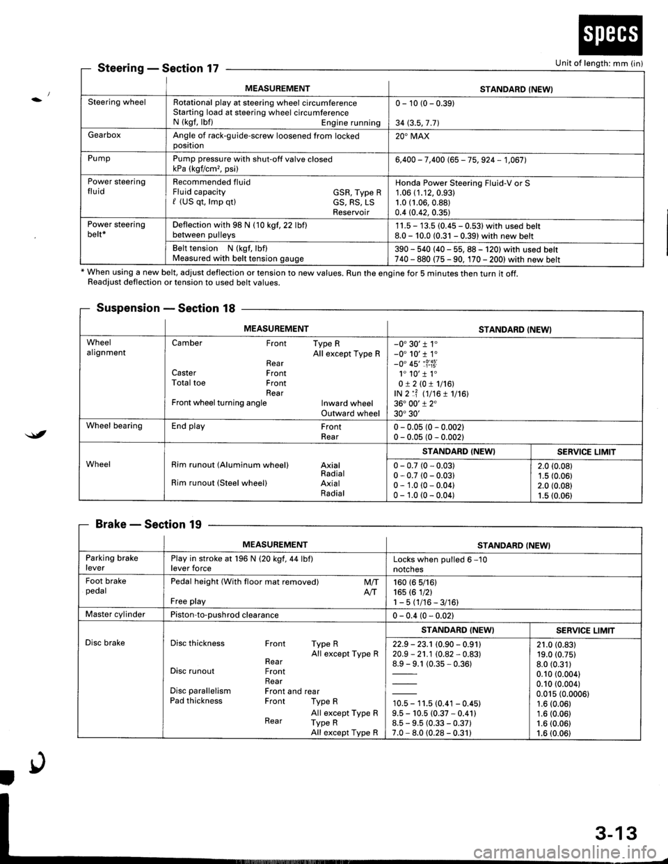
MEASUREMENTSTANDARD (NEWI
Steering wheelRotational play at steering wheel circumferenceStarting load at steering wheel circumferenceN (kgf, lbf) Engine running
0 - 10 (0 - 0.39)
34 (3.5,7 .71
GearboxAngle of rack-guide-screw loosened from lockedoosition20'MAX
PumpPump pressure with shut-off valve closedkPa (kgf/cm,, psi)6,400 - 7,400 (65 - 75, 924 - 1,067],
Power steeringfluidRecommended fluidFluid capacity GSR, Type Rf (US qt, lmp qtl cS, RS, LSReservoir
Honda Power Steering Fluid-V or S1.06 (1.12,0.93)
1.0 (1.06,0.88)
0.4 (0.42, 0.35)
Power steeringbelt*Deflection with 98 N (10 kgf,22 lbflbetween pulleys1 1.5 - 13.5 (0.45 - 0.531 with used belt8.0 - 10.0 (0.31 - 0.39) with new belt
Belt tension N (kgf, lbf)Measured with belt tension gauge390 - 540 (40 - 55, 88 - 120) with used belt740 - 880 (75 - 90, 170 - 2001with new belt
SteeringSection 17
* When using a new belt, adjust deflection or tension to new values. Run the engine for 5 minutes then turn it off.Readiust deflection or tension to used belt values.
Suspension - Section 18
BrakeSection 19
Unit of length: mm (in)
$t
MEASUREMENTSTANDARD (NEWI
WheelalignmentCamber Front Type RAll except Type RRearCaster FrontTotal toe FrontRearFront wheel turning angle Inward wheelOutward wheel
-0'30'r 1"-0' 10'r 1.-0" 45'�1?:i3i1. 10'�1 1.0!210!1116!,lN 2 lf (t7t6 1 1716136. 00'1 2"30'30'
Wheel bearingEnd play FrontRear0 - 0.05 (0 - 0.002)0 - 0.05 (0 - 0.002)
WheelRim runout (Aluminum wheel) AxialRadialRim runout (Steel wheel) AxialRadial
STANDARD (NEW}SERVICE LIMIT
0 - 0.7 (0 - 0.03)0 - 0.7 (0 - 0.03)0 - 1.0 (0 - 0.04)0 - 1.0 (0 - 0.04)
2.0 (0.08)
1.5 (0.06)2.0 (0.08)1.5 (0.06)
MEASUREMENTSTANDARD (NEW}
Parking brakeleverPlay in stroke at 196 N (20 kgf,44 lbf)lever forceLocks when oulled 6 -10
notches
Foot brakepedalPedal height (With floor mat removed)
Free play
M/TAtT160 (6 5/161165 rc 1nl1-5(1/16-3/16)
Master cylinderPiston-to-oushrod clearance0 - 0.4 (0 - 0.021
Disc brakeDisc thickness Front Type RAll except Type RRearDisc runout FrontRearDisc parallelism Front and rearPad thickness Front Type R
All except Type RRear Type RAll except Type R
STANDARD (NEWISERV]CE LIMIT
22.9 - 23.1 (0.90 - 0.91120.9 - 21.1 (0.82 - 0.83)
1= t (0.35-0.361
10.5 - 11.5 (0.41 - 0.45)9.5 - 10.5 (0.37 * 0.41)8.5 - 9.5 (0.33 - 0.37)7.0 - 8.0 (0.28 - 0.31)
21.0 (0.83)19.0 (0.75)
8.0 (0.31)
0.10 (0.004)
0.10 (0.004)
0.015 (0.0006)1.6 (0.06)
1.6 (0.06)1.6 (0.06)
1.6 (0.06)