Transmission assembly HONDA INTEGRA 1998 4.G Owner's Manual
[x] Cancel search | Manufacturer: HONDA, Model Year: 1998, Model line: INTEGRA, Model: HONDA INTEGRA 1998 4.GPages: 1681, PDF Size: 54.22 MB
Page 521 of 1681
Transmission
Removal
. Make sure lifts, iacks and salety stands are placed
properly, and hoist brackets are attached to lhe cor-
rect position on the engine (see section 11.
. Apply parking brake and block real wheels, so vehi-
cle will nol roll off stands and fall on you while work-
ing under it.
CAUTION: Use fender covers to avoid damaging paint-
ed surtaces.
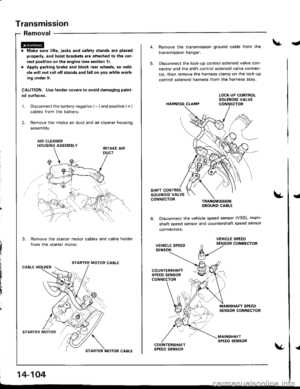
1 . Disconnect the battery negative (- ) and positive { + )
cables from the battery.
2. Remove the intake air duct and air cleaner housing
assemoty.
AIR CLEANERHOUSING ASSEMBLY
Remove the starter motor cables and cable holder
from the starter motor.
MOTOR CABLECABLE HOLDER
STARTER MOTOR'/,/ \
STARTER MOTOR CABI-E
14-104
-
5.
Remove the transmission ground cable from the
transmission hanger.
Disconnect the lock-up control solenoid valve con-
nector and the shift control solenoid valve connec-
tor, then remove the harness clamp on the lock-up
control solenoid harness from the harness s1ay.
HARNESS CLAMP
TRANSMISSIOIGROUND CABLE
Disconnect the vehicle speed sensor (VSS), main-
shalt speed sensor and countershalt speed sensor
connecrors.
{
6.
VEHICLE SPEED
VEHICLE SPEED
ll t2tor coNNEcroR
V
MAINSHAFT SPEEDSENSOR CONNECTOR
MAINSHAFTSPEED SENSORCOUNTERSHAFTSPEED SENSOR{
Page 528 of 1681
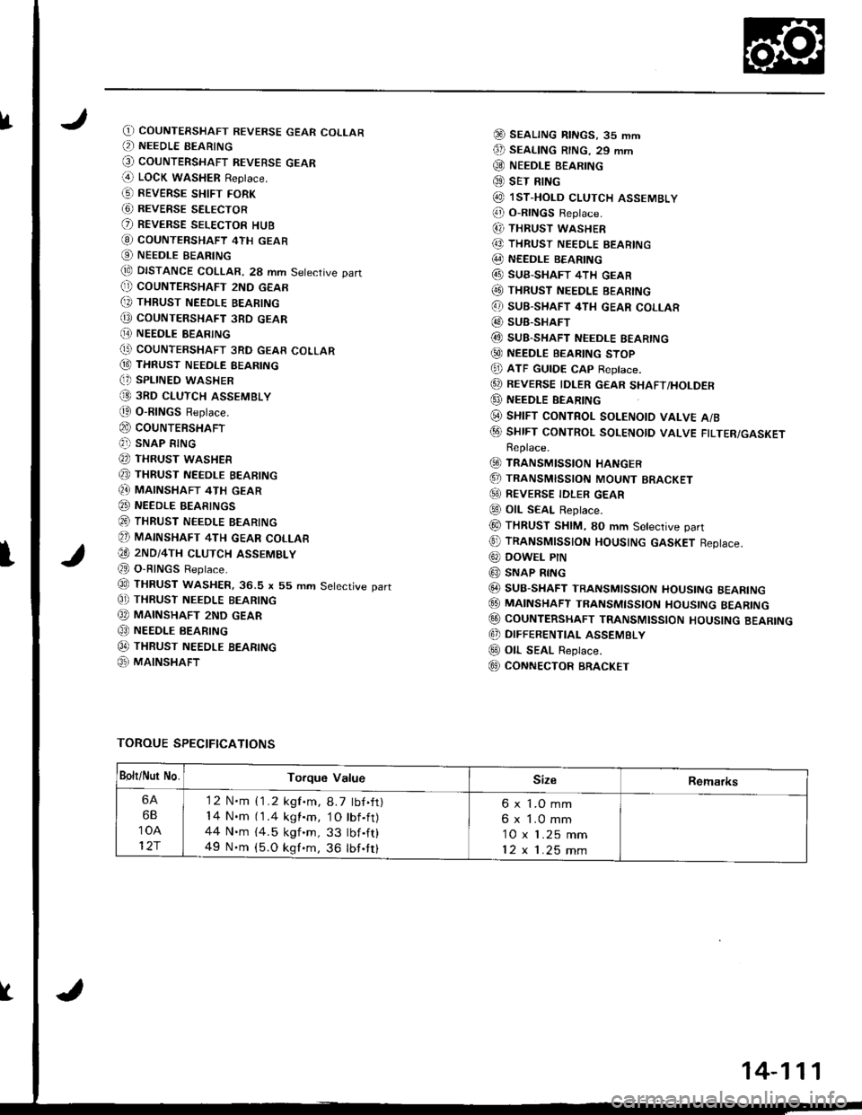
fO) COUNTERSHAFT REVERSE GEAR COLLAR(, NEEDLE BEARING
@ couNTERSHAFT REVEBsE GEAR(4 LOCK waSHER Replace.
G) REVERSE sHtFr FoRK
G) REVERSE SELECTOR
O REVERSE SELEcToR HUB
@ coUNTERSHAFT 4TH GEAR
O NEEDLE BEARING
tE DISTANCE COLLAR, 28 mm Setective part(} COUNTERSHAFT 2ND GEAR
[, THBUST NEEDLE BEARING
@ coUNTERSHAFT 3RD GEAR
[E NEEDI.E BEARING(' COUNTERSHAFT 3RD GEAR COLLAR
@ THRUST NEEDLE BEARING(, SPLINED WASHER
@ 3RD cLUTcH ASSEMBLY
t0 O-RINGS Replace.
@ couNTERSHAFT(?]) SNAP RING
@ THRUST WASHER
@ THRUST NEEDLE BEARING
Q} MAINSHAFT 4TH GEAR
@ NEEDLE BEARINGS
@ THRUST NEEDLE BEARING
@ MAINSHAFT 4TH GEAR coLLAR
€O 2ND/4TH cLUTcH ASSEMBLY
@ O-RINGS Reptace.
@ THRUST WASHER.36.S x 55 mm Setective part
C]) THRUST NEEoLE BEARING
@ MAINSHAFT 2ND GEAR
@ NEEDLE BEARING
0t THRUST NEEDLE BEARTNG
@ MAINSHAFT
@ SEALTNG RtNGs, 35 mm
€D SEAL|NG R|NG. 29 mm
@ NEEDLE B€ARING
@ sET RING
@ lsT.HoLD cLUTCH ASSEMBLY
@ o-RtNGs Reptace.
(, THRUST WASHER
@ THRUST NEEDLE BEARING
@ NEEDLE BEARING
@ SUB-SHAFT 4TH GEAR(O THRUST NEEDLE BEARING
@ sUB-SHAFT 4TH GEAR coLLAR
@ SUB-SHAFT
@ SUB-SHAFT NEEDLE EEARING
@ NEEDLE BEARTNG sToP
@ ATF GUTDE cAp Reptace.
@ REVERSE IDLER GEAR sHAFT/HoLDER
@ NEEDLE BEARING
(i) sHrFT coNTRoL soLENotD vALvE A/B
@ sHrFT coNTRoL soLENotD vALVE FTLTER/GASKETReplace.
@ TRANSMISSIoN HANGER
.5, TRANSMISSIoN MoUNT BRACKET
@) REVERSE TDLER GEAR
@ otL SEAL Replace.
@ THRUST SHIM, SO mm Setective part
@ TRANSMTSSTON HOUSTNG GASKET Reptace.
@ DowEL PtN
@ SNAP RING
@ SUB-SHAFT TRANSMlsstoN HoustNG BEARTNG
@ MA|NSHAFT TRANsMtssroN HoustNG BEARTNG
@ CoUNTERSHAFT TRANSMIssloN HoUsING BEARING
@ DIFFERENTIAL ASSEMBLY
@ oll- SEAL Replace.
E9 CONNECTOR BRACKET
TOROUE SPECIFICATIONS
I
Bolt/Nur No.Torque ValueSizeRemarks
6A
6B
10A
12r
'12 N.m {1.2 kgf.m, 8.7 tbf.ft)14 N.m (1.4 kgl.m, 1O tbf.ft)44 N.m {4.5 kgf 'm, 33 tbf .ft}
49 N.m (5.O kgf.m, 36 lbf.tt)
6 x 1.O mm
6 x 1.0 mm
10 x 1.25 mm
12x1.25mm
14-111
Page 531 of 1681
Right Side Cover
Removal
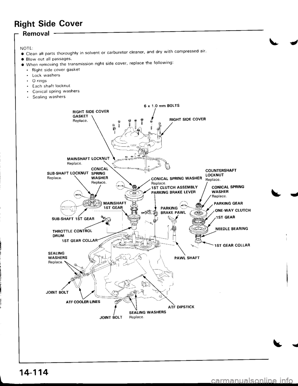
NOTE:
a Clean all parts thoroughly in solvent or carburetor cleaner' and dry with compressed alr'
a Blow out all Passages.
a When removing the transmission right side cover, replace the following:
. Right side cover gasket
. Lock washers. O rings. Each sha{t locknut
. Conical spring washers
. Sealing washers
RIGHT SIDE COVER
GASKETBeplace.
J
mm BOLTS6x1.0
,c
B,
MAINSHAFTReplace.LOCKNUT
RIGHT SIDE COVER
CONICAL SPRING WASHER
COUNTERSHAFTLOCKNUTSUB-SHAFT LOCKNUTReplace.
CONICALSPRINGWASHERReplace.Replace.1ST CLUTCH ASSEMBLY
PARKING BRAKE LEVERCONICALWASHERReplace.
SPRING
J
\-_7
SUB-SHAFT 1
PARKING GEAR
ONE-WAY CLUTCH
1ST GEAR
NEEOLE BEARING
1ST GEAR COLLAR
SEALINGWASHERSReplace.
JOINT BOLT
otPsTtcK
SEALING WASHERSReplace.
t
'::-Pf.a
THROTTLE CONTROLDRUM
1ST GEAB
ATF COOLER LINES
'. .)
14-114
I
Page 532 of 1681
I
t
I
1.
2.
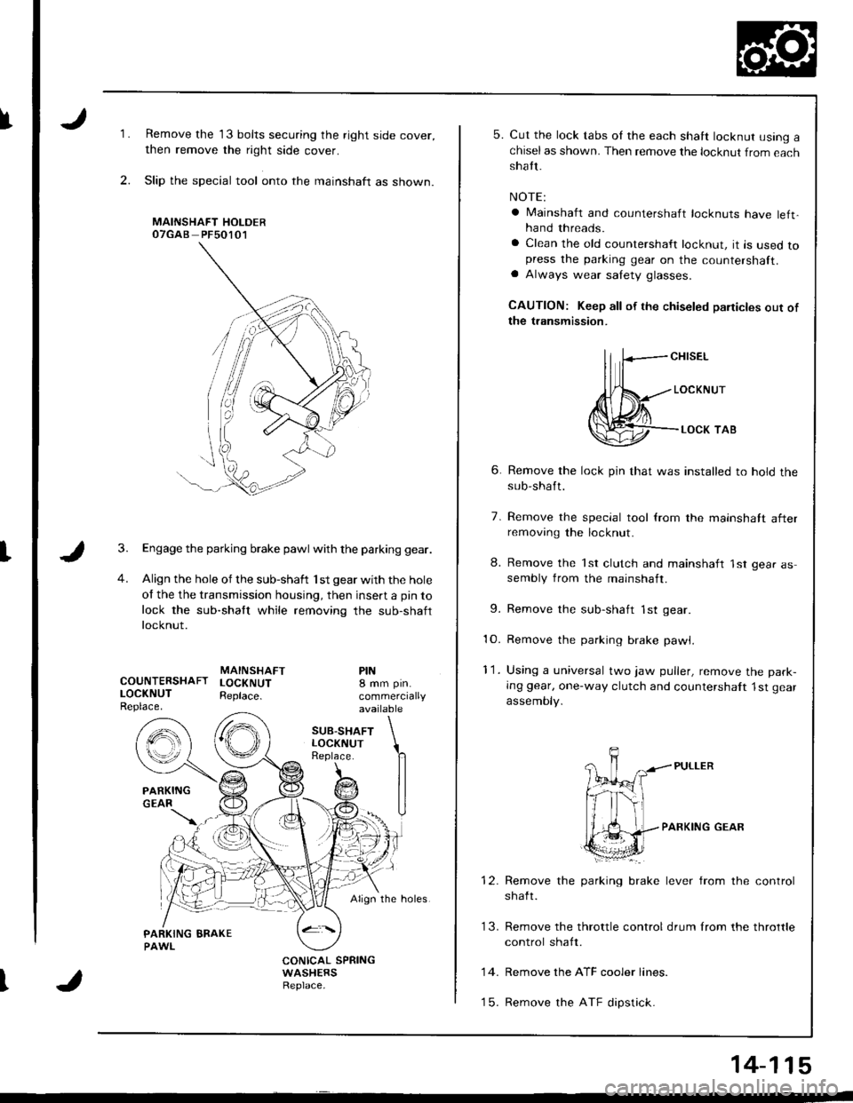
Remove the 13 bolts securing the right side cover,
then remove the right side cover.
Slip the special tool onto the mainshaft as shown.
MAINSHAFT HOLDEROTGAB PFsO1O1
Engage the parking brake pawl with the parking gear.
Align the hole of the sub-shaft 'lst gear with the hole
of the the transmission housing, then insert a pin to
lock the sub-shaft while removing the sub-shaft
locknut.
MAINSHAFTCOUNTERSHAFT LOCKNUTLOCKNUT Reptace.Replace.
PIN8 mm pin.
commerciallyavailable
SUB.SHAFTLOCKNUTReplace.
Align the holes.
CONICAL SPRINGWASHERSReplace.
5. Cut the lock tabs oI the each shaft locknut using achiselas shown. Then remove the locknut from eachshatt.
NOTE:
a lvlainshaft and countershaft locknuts have left,hand threads.
a Clean the old countershaft locknut, it is used topress the parking gear on the countershaft.a Always wear salety glasses.
CAUTION: Keep all of the chiseled paiticles out ofthe transmission.
ll fcH,sEL
Jl{*---,o"*",r
@--.**,o,
6. Remove the lock pin that was installed to hold thesub-shaft.
7. Remove the special tool from the mainshatt afterremoving the locknut.
8. Remove the 'lst clutch and mainshaft 'lst gear assembly from the mainshaft.
9. Remove the sub-shaft 1st gear
10. Remove the parking brake pawl,
11. Using a universal two jaw puller, remove the park-
Ing gear, one-way clutch and countershalt 1st gear
assemoty.
PARKING GEAR
brake lever from the controlRemove the parking
shaft.
Remove the ATF cooler lines.
Remove the ATF dipstick.
13. Remove the throttle control drum lrom the throttle
control shaft.
14.
t5.
14-115
Page 533 of 1681
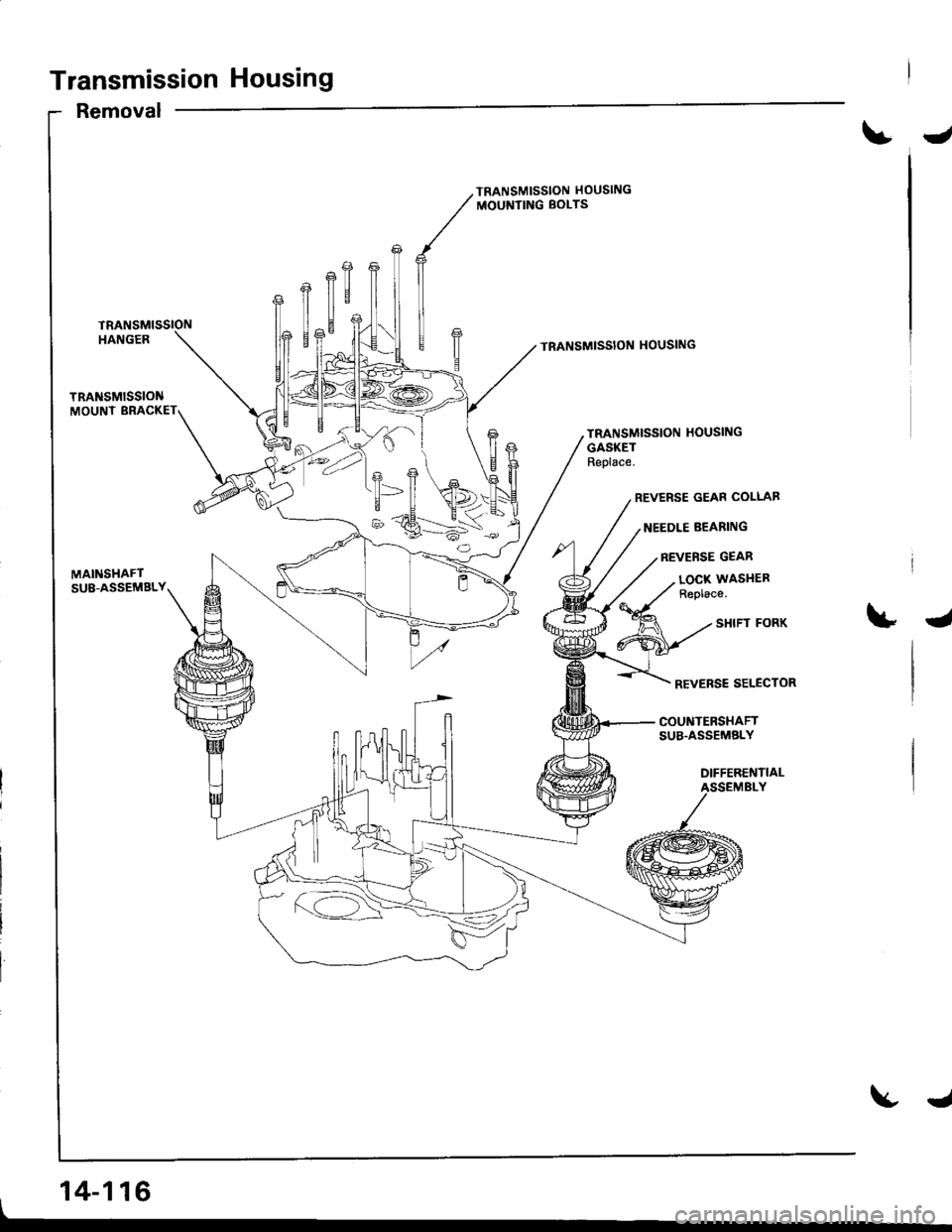
Transmission Housing
Removal
J
TRANSMISSION HOUSING
MOUNTING BOLTS
TRANSMISSION HOUSING
TRANSMISSION HOUSING
GASKETReplace.
REVERSE GEAR COLLAB
NEEDLE BEARING
REVERSE GEAR
MAINSHAFTSU8-ASSEMBLY
, 14-116
LOCX WASITEFReplace.
4
REVERSE SELECTOR
COUNTERSHAFTSUB.ASSEMELY
DIFFERENTIALASSEMBLY
J
Page 534 of 1681
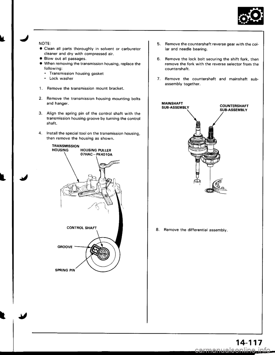
fNOTE:
a Clean all parts thoroughly in solvent or carburetor
cleaner and dry with compressed air.a Blow out all passages.
a When removing the transmission housing, replace the
tollowing:. Transmission housing gasket. Lock washer
1. Remove the transmission mount bracket.
2.Remove the transmission housing mounting bolts
and hanger.
Align the spring pin of the control shatr wirh the
transmission housing groove by turning the control
shatt.
Install the special tool on the transmission housing,
then remove the housing as shown.
TRANSMISSTONHOUSING HOUSING PULLER
5.
6.
Remove the countershaft reverse gear with the col-
lar and needle bearing.
Remove the lock bolt securing the shilt fork. then
remove the fork with the reverse selector from the
countershatt.
Remove the countershaft and mainshaft sub-
assembly together.
8. Remove the differential assemblv.
7.
14-117
Page 551 of 1681
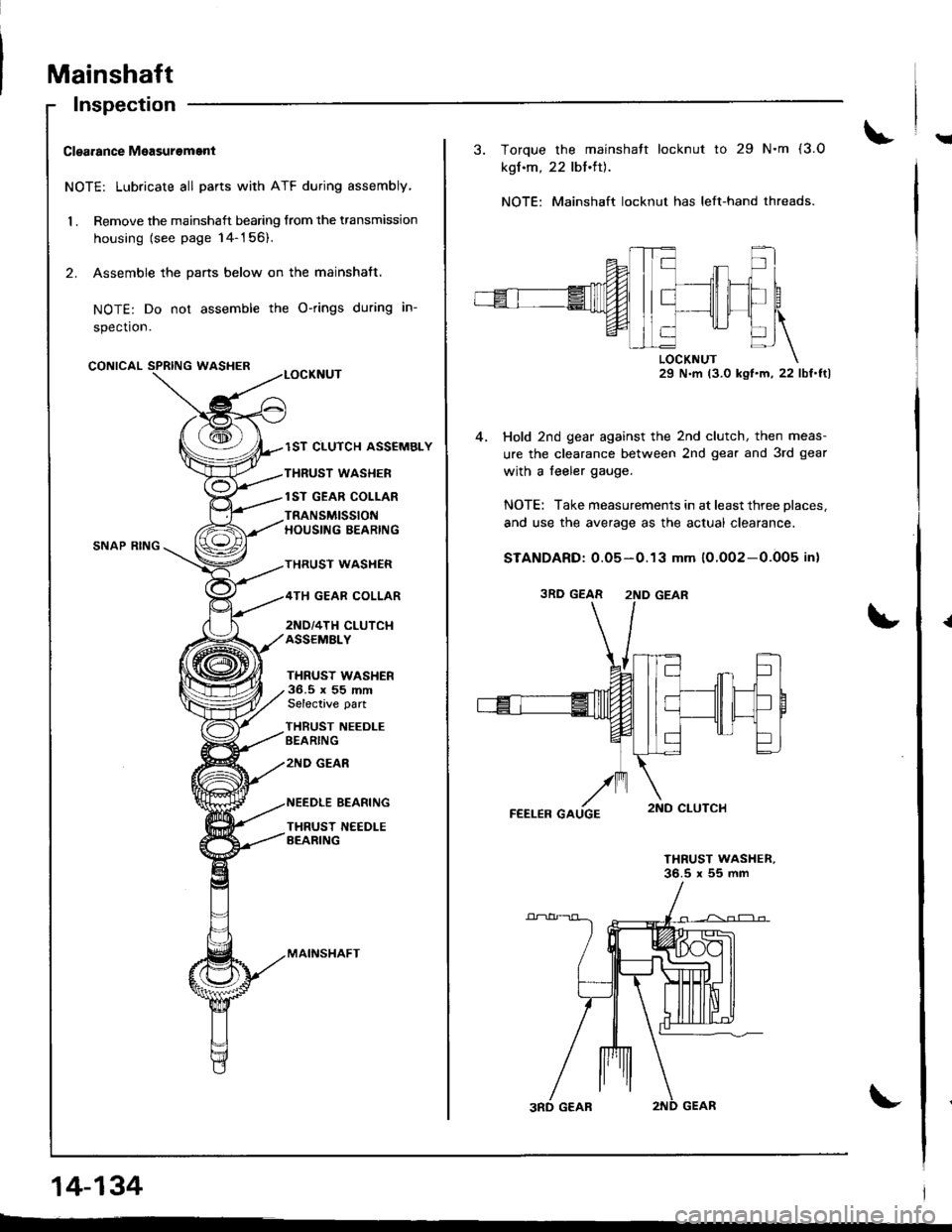
Mainshaft
!Clgarance Measurement
NOTE: Lubricate all parts with ATF during assembly,
1 . Remove the mainshaft bearing from the transmission
housing {see page 14-156).
2. Assemble the pans below on the mainshaft.
NOTE: Do not assemble the O-rings during in-
spection.
CONICALWASHER
Inspection
SNAP RING
lST CLUTCH ASSEMBLY
THRUST WASHER
lST GEAR COLLAR
TRANSMISSIONHOUSING BEARING
THRUST WASHER
TH GEAR COLLAR
2ND/4TH CLUTCI{ASSEMALY
THRUST WASHER36.5 x 55 mmSelective part
THRUST NEEDLEBEARING
zND GEAR
BEARING
THRUST N€EDLEBEARING
MAINSHAFT
14-134
3. Torque the mainshatt locknut to 29 N.m (3.O
kgf.m, 22 lbt.tt).
NOTE: Mainshaft locknut has left-hand threads.
29 N.m (3.0 ksl'm,22 lbf'ftl
Hold 2nd gear against the 2nd clutch, then meas-
ure the clearance between 2nd gear and 3rd gear
with a feeler gauge.
NOTE: Take measurements in at least three places,
and use the average as the actual clearance.
STANDARD: 0.05-0.13 mm 10.002-0.005 in)
THRUST WASHER,36.5 x 55 mm
3RD GEAR 2ND GEAR
Page 556 of 1681
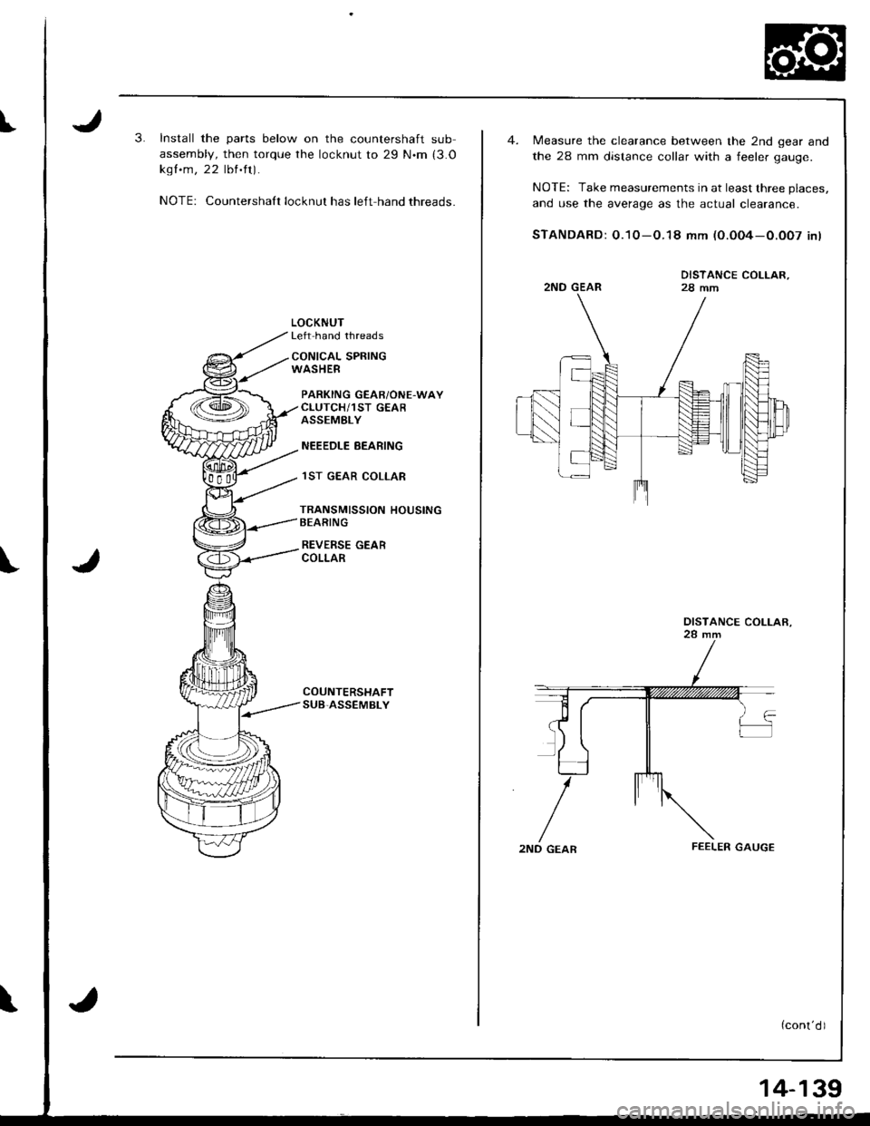
I3.Install the parts below on the countershaft sub
assembly, then torque the locknut to 29 N.m (3.O
kgf .m, 22 lbl'ft).
NOTE: Countershalt locknut has left hand threads.
LOCKNUTLeft hand threads
CONICAL SPRINGWASHEB
PARKING GEABiONE.WAYCLUTCH/1ST GEARASSEMELY
NEEEDLE EEARING
lST GEAR COLLAR
TRANSMISSION HOUSINGBEARING
REVERSE GEARCOLLAR
COUNTERSHAFTSUB,ASSEMBLY
Measure the clearance between the 2nd gear and
the 28 mm distance collar with a feeler oauoe.
NOTE: Take measurements in at least three places,
and use the average as the actual clearance.
STANDARD: O.10-O.18 mm (O.0O4-O.OO7 inl
2ND GEARFEELER GAUGE
DISTANCE COLLAR,
DISTANCE COLLAR.
14-139
Page 559 of 1681
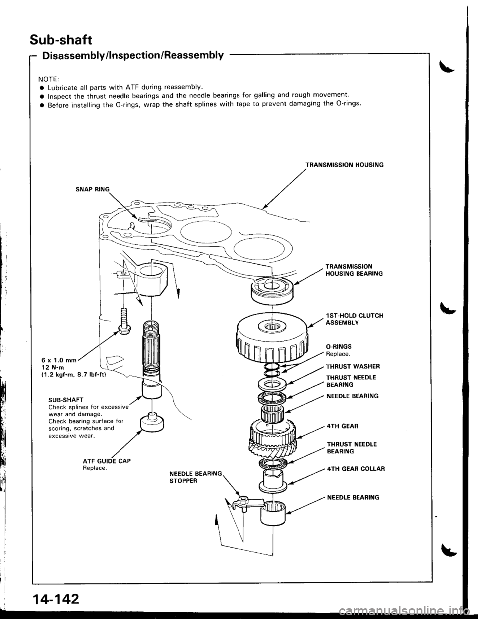
Sub-shaft
Disassembly/lnspection/Reassembly
NOTE:
a Lubricate all parts with ATF during reassembly.
a Inspect the thrust needle bearings and the needle bearings for galling and rough movement'
a Before installing the o-rings, wrap the shaft splines with tape to prevent damaging the o-rings.
TRANSMISSION HOUSING
TRANSMISSIONHOUSING BEARING
1ST-HOLO C|-UTCHASSEMBLY
O-RINGSReplace.
THRUST WASHER
THRUST NEEDLEBEARING
NEEDLE BEARING
4TH GEAR
THRUST NEEDLEAEARING
4TH GEAR COLLAR
NEEDLE BEARING
6 x 1.0 mm12 N.m(1.2 kgf.m, 8.7 lbf.tt)
SUB-SHAFTCheck splines for excessivewear and oamage.Check bearing surface forscoring, scratches and
ATFReplace-NEEDLE BEARINGSTOPPEB
14-142
Page 560 of 1681
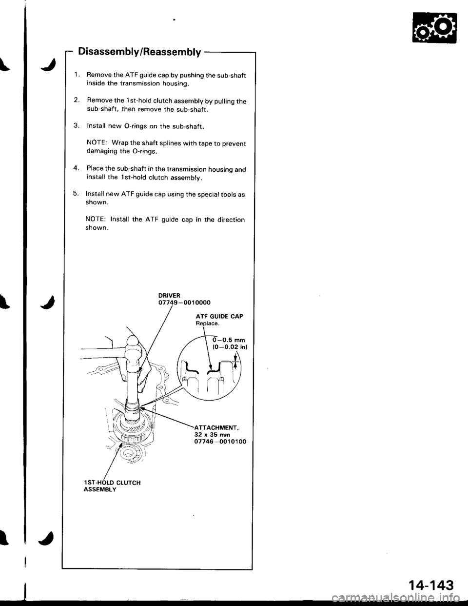
t
Disassembly/Reassembly
Remove the ATF guide cap by pushing the sub-shaftinside the transmission housing.
Remove the 1st-hold clutch assembly by pulling thesub-shaft, then remove the sub-shaft.
Install new O-rings on the sub-shaft.
NOTE: Wrap the shaft splines with tape to preventdamaging the Orings,
Place the sub-shaft in the transmission housing andinstall the 1st-hold clutch assembly.
Install new ATF guide cap using the specialtools asshown.
NOTE: Install the ATF guide cap in the direction
shown.
ORIVER
TTACHMENT,32x35mm07746-O010100
CLUTCHASSEMBLY
14-143