Transmission assembly HONDA INTEGRA 1998 4.G User Guide
[x] Cancel search | Manufacturer: HONDA, Model Year: 1998, Model line: INTEGRA, Model: HONDA INTEGRA 1998 4.GPages: 1681, PDF Size: 54.22 MB
Page 409 of 1681
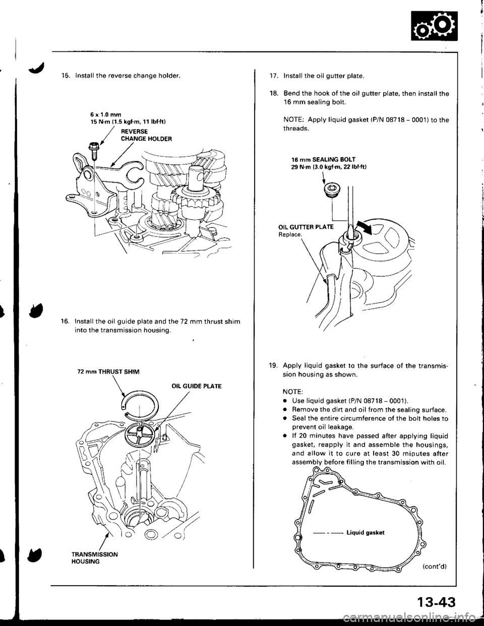
'15. lnstall the reverse chanqe holder.
6x1.0mm15 N.m 11.5 kgt m, l l lbf.ft)
16.Install the oil guide plate and the 72 mm thrust shim
into the transmission housing.
72 mm THBUST SHIM
fl
t
i
17.Install the oil gutter plate.
Bend the hook of the oil gutter plate, then install the
16 mm sealing bolt.
NOTE: Apply liquid gasket (P/N 08718 - 0001)to the
threads.
16 mm SEALING BOLT29 N.m 13.0 kgt.m, 22 lbf.ftl
Apply ljquid gasket to the surface of the transmis-
sion housing as shown.
NOTE:
. Use liquid gasket (P/N 08718 - 0001).. Remove the dirt and oil from the sealing surface.. Seal the entire circumterence of the bolt holes to
prevent oil leakage.
. lf 20 minutes have passed after applying liquid
gasket, reapply it and assemble the housings,
and allow it to cure at least 30 minutes after
assembly before filling the transmission with oil.
(cont'd)
18.
19.
Liquid gaskot
13-43
Page 410 of 1681
Transmission
20.
21.
Reassembly (cont'dl
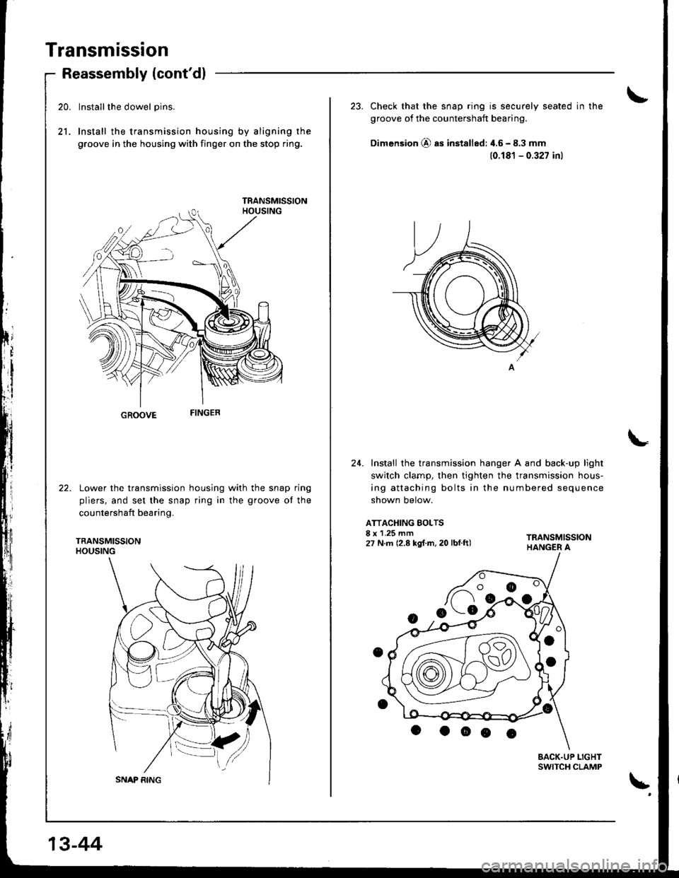
Installthe dowel pins.
Install the transmission housing by aligning the
groove in the housing with finger on the stop ring.
GROOVE
Lower the transmission housing with the snap ring
pliers, and set the snap ring in the groove of the
countershaft bearing.
TRANSMISSIONHOUSING
13-44
23. Check that the snap ring is securely seated in the
groove of the countershaft bearing.
Dimension @ as installed: 4.6 - 8.3 mm
(0.181 - 0.327 inl
24. Install the transmission hanger A and back-up light
switch clarnp, then tighten the transmission hous-
ing attaching bolts in the numbered sequence
shown below.
ATTACHING BOLTSI x 1.25 mm27 N.m (2.8 kgf.m, 20 lbf.ft)
BACK.UP LIGHTSWITCH CLAMP
\'
Page 412 of 1681
I
Transmission Assembly
1.
2.
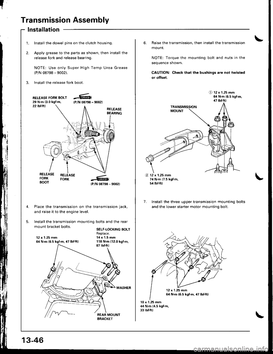
Install the dowel pins on the clutch housing.
Apply grease to the parts as shown, then install the
release fork and release bearing.
NOTE: Use only Super High Temp Urea Grease
(P/N 08798 - 9002).
3. Install the release fork boot.
lnstallation
22 tbl.lll
RELEASE FORK BOLT29 N.m {3.0 kgl.m,{P/N 08798 - 9002t
RELEASEBEAFING
RELEASEFORK
lPlN 08798 - 90021
Place the transmission on the transmission jack,
and raise it to the engine level.
Install the transmission mounting bolts and the rear
mount bracket bolts.SELF.LOCKING BOLT
12 x 1.25 mm64 N.m {6.5 kgf.m, {7 lbtftl
Replace.14 x 1.5 mm
RELEASEFORKBOOT
\i'l-r )i-
.+.i
13-46
6. Raise the transmission, then install the transmission
mounr,
NOTE: Torque the mounting bolt and nuts in the
sequence shown.
CAUTION: Check that the bushings are not twisted
or offset.
!) tz x t.zs mm64 N.m {6.5 kgt.m,47 tbl.ftl
7. Install the three upper transmission mounting
and the lower staner motor mountinq bolt.
bolts
10 x 1.25 mm44 N.m (4.5 kgt m.33 tblftl
(a 12 x 1.25 mm74 N.m {7.5 kgf m,54 tbf.ft)
'12x1.25m�n
64 N.m {6.5 kst.m,47 lbf,ft)
Page 414 of 1681
[!
"
Transmission Assembly
Installation (cont'd)
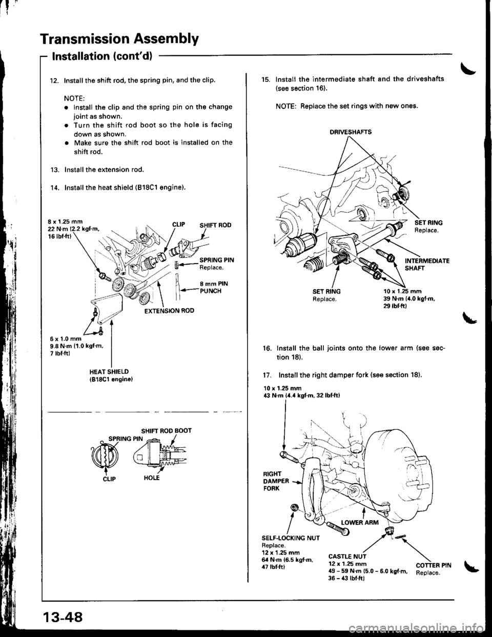
Install the shift rod, the spring pin, and the clip.
NOTE:
. lnstall the clip and the spring pin on the change
joint as shown.
. Turn the shift rod boot so the hole is facing
down as snown.
. Make sure the shift rod boot is installed on the
shift rod.
lnstall the extension rod.
Installthe heat shield (818C1 engine).'t 4.
8 x 1.25 mm22 N.m 12.2 kgfm.16lbt.ft)
I e--erru
1 l+.-PUNCH
EXTENSION ROD
6x1.0mm9.8 N.m 11.0 kgf m,? rbf.ft)
SHIFT ROD BOOT
^ SPRING PIN -- -1
?ffi A'W
Nfu *rry
CLlp HOLE
13-48
DRIVESHAFTS
15. lnstall the intermediate shaft 8nd the driveshafts
(see section 16).
NOTE: Beplace the set rings with new ones.
16. Install the ball joints onto the lower arm (soe ssc-
tion 18).
17. Install the right damper fork (see ssction 18).
10 r 1.25 mm43 N.m lir.a kgt m. 32 lbtftl
LOWER ARM
SELF.LOCKING NUTReplace.12 x 1,25 mm6a N.m 16.5 kg{.ft,/u rbl.tt)
CASTLE NUT12 x 1.25 mm49 - 59 N.m (5.0 - 6.0 kgf.m, Reptace.35 - 43 lbf.ftl
"\
COTTER PIN
Page 416 of 1681
Transmission Assembly
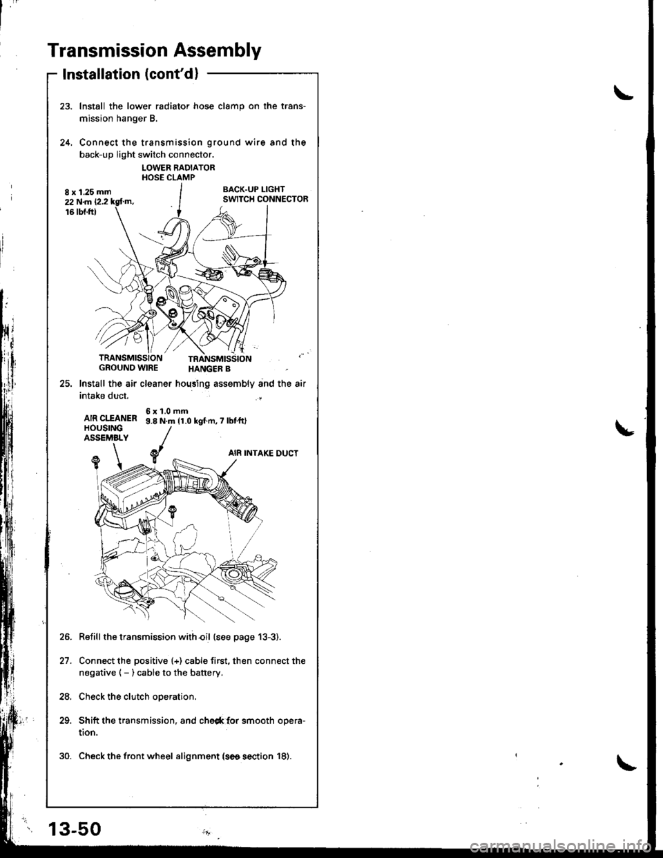
Installation (cont'd)
Install the lower radiator hose clamp on the trans-
mission hanger B.
Connect the transmission ground wire and the
back-up light switch connector.
LOWER RADIATORHOSE CLAMP
BACK.UP I-IGHTSWITCH CONNECTOR
24.
TRANSMISSIONGROUND WIRE
25. lnstall the air cleaner
intake duct.
AIR CIfANERHOUSINGASSEMBLY
HANGER B
hoqsing assembly and the air
6x1.0mm9.8 N.m 11.0 kgf.n,7 lbt'ft)
AI8 INTAKE DUCTY1
Reiill the transmission with€il (see page 13-3).
Connect the positive (+) cable first, then connect the
negative ( - ) cable to the battery.
Check the clutch operation.
Shift the transmission, and che6* {or smooth opera-
tion.
30. Check the front wheel alignment (se6 section 18).
21.
24.
13-50
Page 418 of 1681
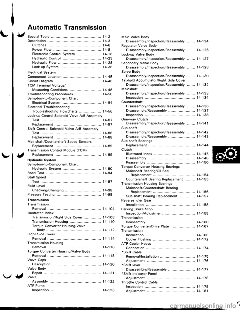
Automatic Transmission
Special Tools ................ '14-2
Descraption .................... 14-3
Clutches ............ ...... 14-6
Power Flow ..,........... 14-8
Electronic Control System ..................... 1 4-1 8
Hydraulic Control ...... 14-23
Hydraulic Flow .........- 14-28
Lock-up System ........ 14-38
Electrical System
Component Location -................................ 1 4-45
Circuit Diagram ............. 14-46
TCM Terminal Voltage/
Measuring Conditions ......,.................... 1 4-48
Troubleshooting Procedures .. . ... ........ ...... ... 14-50
Symptom-to-Component Chart
Electrical System ...... 14-54
Electrical Troubleshooting
Troubleshooting Flowcharts .......... ... ...,.. 14-56
Lock-up Control Solenoid Valve A/B Assembly
Test .................. ...... 14-A7
Replacement ............. 14-a7
Shilt Control Solenoid Valve A/B Assembly
Test .................. ...... '14-88
Replacement .,..,........ 14-88
lvlainshaf t/Countershaft Speed Sensors
Replacement ....-......,. 14-89
Transmission Control Module (TCM)
Replacement ............. 14-89
Hydraulic System
Symptom-to-Component Chart
Hydraulic System ...... 14-90
Road Test ,................... 14-94
Stall Speed
Test .................. ...... 14-97
Fluid Level
Checking/Changing .... 14-98
Pressure Testing ........... 14-99
Transmission
Transmission
Removal ............. ...... 14-10�4
lllustrated lndex
Transmission/Right Side Cover ............... 1 4-1 08
Transmission Housin9 ................,..,....... 1 4-1'1 O
Torque Converter Housing/ValveBody .................. .. 14-112
Right Side Cover
Removal ............. ...... 14-114
Transmission Housing
Removal ............. ...... 14-1 l6
Torque Converter Housing/Valve Body
Removal ............. ...... l4-1 18
Valve Caps
Description ...........-... 14-120
Valve Body
Repair ................ ...... 14-12'l
Valve
Assembly
ATF Pump
Inspeclton
Main Valve Body
Disassembly/lnspection/Reassembly
Regulator Valve Body
Disassembly/lnspection/Reassembly
Lock-up Valve Body
Disassembly/lnspection/Reassembly
Secondary Valve Body
Disassembly/lnspection/Reassembly
Servo Body
....... 14-124
....... 14-126
....... 14-127
....... 14 124
Disassembly/lnspection/Reassembly .......
1st-hold Accumulator/Right Side Cover
Disassembly/lnspection/Reassembly .......
Mainsha{t
14-130
14-132
Disassembly/lnspection/Reassembly ....... 14-133
Inspection ................. 14-134
Countershaft
Disassembly/lnspection/Reassembly,..,.., l4-136
Disassembly/Reassembly ..,...,..,.........,,.. 1 4-1 37
Inspection ......,...,..,... 14-138
One-way Clutch
Disassembly/lnspection/Reassembly ....,.. 14-141
Sub-shaft
Disassembly/lnspection/Reassembly ...,,..'14-142
Disassembly/Reassembly ....................... 1 4- l 43
Sub-shaft Bearings
Replacement ,..,,.,,..,.. 14-144
Clutch
lllustrated Index ................................... I 4-1 45
Disassembly ............. 14-144
Reassembly .............. 14-150
Torque Converter Housing Bearings
Mainshaft Bearing/Oil Seal
Replacement ......... 14-154
Countershaft Bearing Replacement ......... 1 4- 1 55
Transmission Housing Bearings
Mainshaft/Countershaft BearingReplacement ......,.. 14-'156
Sub-shaft Bearing Replacement .,............ 1 4-1 57
Reverse ldler Gear
Installation .........-..... 14-158
Parking Brake Stop
Inspection/Adjustment .......................... 1 4-1 58
Transmission
Reassembly .............. 14-160
Torque Converler/Drive Plate ..............,.,,.,, 1 4-1 67
Transmission
Installation ............... 14-168
Cooler Flushing ......... 14-172
ATF Cooler Hoses
Connection ,..,,,....,,.,, '14-'174
*shift cable
Removal/lnstallation . . .. .... ... .... ... .... .. . ... .. 14-'l75
Adjustment ,..,...,,,,.,, 14-'116*Shilt lever
Disassembly/Reassembly ....................... 1 4-'17 7'Shift Indicator Panel
Adjustment .............. 14-178
\l
)g
Page 420 of 1681
Description
\J
t{
{
14-3
The automatic transmission is a combination of a 3-element torque converter and triple-shalt electronically controlled
automatic transmission which provides 4 speeds forward and 1 speed reverse. The entire unit is positioned in line with
the engrne.
Torque Converter, Gears, and Clutches
The torque converter consists of a pump, turbine, and stator, assembled in sigle unit. The torque converter is connected to
the engine crankshaft so they turn torether as a unit as the engine turns. Around the outside of the torque convener is a
ring gear which meshes with the starter pinion when the engine is being started. The entire torque converter assembly
serves as a flywheel while transmitting power to the transmission mainshaft.
The transmission has three parallel shafts; the mainshaft. the countershaft, and the sub shaft. The mainshaft is in-line with
the engine crankshaft.
The mainshaft includes the 1st, and 2ndl4th clutches,and gear for 3rd, 2nd, 4th, reverse, and 1st. (3rd gear is integral with
the mainshaft, while reverse gear is integral with the 4th gear.)
The countershaft includes the 3rd clutch and gears for 3rd,2nd, 4th, reverse, 1st, and parking. Reverse and 4th gears can
be loched to the countershaft at its center,providing 4th gear or reverse, depending on which way the selector is moved.
The sub-shaft includes the 1st-hold clutch and gears fo 1st and 4th.
The gears on the mainshaft are in constant mesh with those on the countersahft and sub-shaft.When certain combinations
of gears in the transmission are engaged by clutches. power in transmitted from the mainshaft to the countershaft via the
sub-shaft to orovude oil, lo'1. E, E. and E.
Electronic Control
The electronic control svstem consists of the Transmission Control Module (TCM), sensors, and four solenoid valves.
Shilting and lock-up are electronically controlled for comfortable driving under all conditions.
The TCM is located below the dashboard, behind the lelt side kick panel on the driver's side.
Hydraulic Control
The valve bodies include the main valve body, the secondary valve body, the regulator valve body, the serbvo body, and
the lock-up valve body, through the respective separator plates, They are bolted to the torque converter housing,
The main valve body contains the manual valve, the 1-2 shift valve, the 2-3 shitt valve, the Clutch Pressure Control
lCPC) valve, the 4th exhaust valve, the reliel valve, and the ATF pump gears.
The secondary valve body contains the 4-3 kick-down valve, the 3-2 kick-down valve, the 2-3 orifice control valve, the
3-4 shift valve, the orilice control valve, the modulator valve, and the servo control valve.
The regulator valve body contains the pressure regulator valve, the lock-up control valve, the torque converter check
valve, and the cooler check valve.
The servo body contains the servo valve, which is integrated with shift fork shaft, the throttle valve B, and the accumula-
tors.
The lock-up valve body contains the lock-up shift valve and the lock-up timing B valve, and is bolted to the regulator valve
ooqy.
Fluid from the regulator passes through the manual valve to the various control valves.
Shift Control Mechanism
Input to the TCM from various sensors located throughout the car determines which shift control solenoid valve should
be activated. Activating a shitt control solenoid valve changes modulator pressure, causing a shift valve to move. This
pressurizes a line to one ol the clutches, engaging that clutch and its corresponding gear.
Lock-uD Mechanism
In @ position, in 2nd, 3rd and 4th, and @ position in 3rd, pressurized fluid can be drained lrom the back oI the tor-
que converter through a fluid passage, causing the lock-up piston to be held against the torque converter cover. As this
takes place, the mainshaft rotates at the same speed as the engine crankshaft. Together with hydraulic control, the TCM
optimizes the timing of the lock-up mechanism.
The lock-up valves controlthe range of lock-up according to lock-up control solenoid valves A and B, and throttle valve B.
When lock-up control solenoid valves A and B activate, modulator pressure changes. Lock-up control solenoid valves
A and B are mounted on the torque converter housing, and are controlled by the TCM.
(cont'd)
Page 509 of 1681
![HONDA INTEGRA 1998 4.G User Guide The following symptoms can be caused
by improper repair or assembly
Checkthese items on the
PROBABLE CAUSE DUE TO
IMPROPER REPAIR Llst
Items on the
NOTES List
Vehicle creeps in E] position.R1, R2
Vehi HONDA INTEGRA 1998 4.G User Guide The following symptoms can be caused
by improper repair or assembly
Checkthese items on the
PROBABLE CAUSE DUE TO
IMPROPER REPAIR Llst
Items on the
NOTES List
Vehicle creeps in E] position.R1, R2
Vehi](/img/13/6069/w960_6069-508.png)
The following symptoms can be caused
by improper repair or assembly
Checkthese items on the
PROBABLE CAUSE DUE TO
IMPROPER REPAIR Llst
Items on the
NOTES List
Vehicle creeps in E] position.R1, R2
Vehicle does not move in l&l or Lql position.R4
Transmittion locks up in E] position.R3, R12
Excessive drag in transmission.R6K,R
Excessive Vibration, rpm related.R7
Noise with wheels moving only.R5
Msin soal pops out,R8
Various shifting problems.R9, R1O
Harsh upshifts.Rl l
Symptom-to-Gomponent Ghart
Hydraulic System (cont'd)
14-92
\.J
v.4
\/J
PROBABLE CAUSE DUE TO IMPROPER REPAIR
R1lmproper clutch clearance.
R2.lmproper gear clearance.
R3.Parking brake lever installed upside down.
R4.One-way (sprag) clutch installed upside down.
R5.Reverse selector hub installed uoside down.
R6.ATF pump binding.
R7.Torque converter not fully seated in ATF pump.
R8.Main seal improperly installed.
R9.Springs improperly installed.
R10.Valves improperly installed.
R11Ball check valves not installed.
R12.Shift tork bolt not installed.
Page 510 of 1681
NOTES
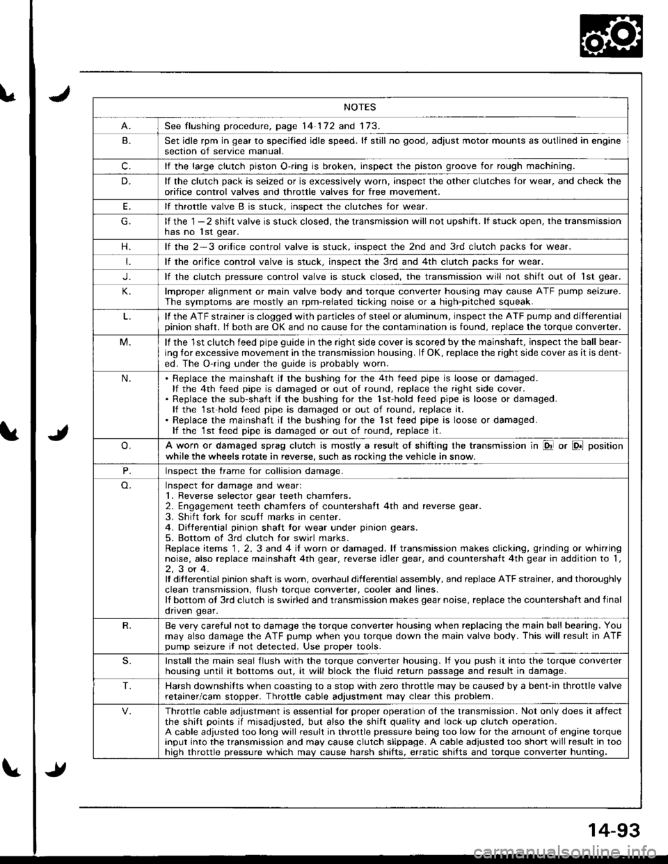
See flushing procedure, page 14-172 and 173.
B.Set idle rpm in gear to specilied idle speed. lf still no good, adjust motor mounts as outlined in enginesection of service manual.
c.lf the large clutch piston O-.ing is broken, inspect the piston groove for rough machining.
D.lf the clutch pack is seized or is excessively worn, inspect the other clutches lor wear, and check the
orifice control valves and throttle valves for free mov€ment.
E.lf throttle valve B is stuck. insDect the clutches for wear.
lf the 1 - 2 shift valve is stuck closed, the transmission will not upshitt. lf stuck open, the transmissionhas no lst gear.
H.lf the 2-3 orilice control valve is stuck, inspect the 2nd and 3rd clutch packs for wear.
lf the orifice control valve is stuck. inspect the 3rd and 4th clutch packs for wear.
J.lf the clutch pressure control valve is stuck closed, the transmission will not shift out oI 1st gear.
lmproper alignment or main valve body and torque converter housing may cause ATF pump seizure.
The symptoms are mostly an rpm-related ticking noise or a high-pitched squeak.
lf the ATF strainer is clogged with particles of steel or aluminum, inspect the ATF pump and differentialpinion shaft. lf both are OK and no cause for the contamination is found, replace the torque converter.
M.lf the 1st clutch feed pipe guide in the right side cover is scored by the mainshaft, inspect the ball bear-
ing lor excessive movement in the transmission housing. lf OK, replace the right side cover as it is dent-
ed. The O-ring under the guide is probably worn.
N.Replace the mainshaft if the bushing for the 4th feed pipe is loose or damaged.lf the 4th feed pipe is damaged or out of round, replace the right side cover.Replace the sub-shaft il the bushing for the 1st-hold teed pipe is loose or damaged.lf the 1st-hold teed pipe is damaged or out of round, replace it.
Replace the mainshaft iI the bushing for the lst feed pipe is loose or damaged.lf the 1st leed pipe is damaged or out of round, replace it.
A worn or damaged sprag clutch is mostly a result of shifting the transmission in El or LDll position
while the wheels rotate in reverse, such as rocking the vehicle in snow.
P.Inspect the trame for collision damage.
Inspect lor damage and wear:1. Reverse selector gear teeth chamfers.2. Engagement teeth chamfers of countershaft 4th and reverse gear.
3. Shift fork for scuff marks in center.4. Differential pinion shaft tor wear under pinion gears.
5. Bottom of 3rd clutch for swirl marks.Replace items 1 . 2, 3 and 4 iI worn or damaged. lf transmission makes clicking, grinding or whirringnoise, also replace mainshaft 4th gear, reverse idler gear, and countershatt 4th gear in addition to '1,
2,3or4.It differential pinion shalt is worn, overhaul differential assembly, and replace ATF strainer, and thoroughly
clean transmission, tlush torque conveder, cooler and lines.lf bottom ot 3rd clutch is swirled and transmission makes gear noise, replace the countershaft and final
onven qear.
R.Be very careful not to damage the torque converter housing when replacing the main ball bearing. You
may also damage the ATF pump when you torque down the main valve body. This will result in ATFpump seizure if not detected. Use proper tools.
S.Install the main seal llush with the torque converter housing. lf you push it into the torque converterhousing until it bottoms out. it will block the fluid return passage and result in damage.
T.Harsh downshifts when coasting to a stop with zero throttle may be caused by a bent-in throttle valve
retainer/cam stopper. Throttle cable adjustment may clear this problem.
Throttle cable adjustment is essential tor proper operation ol the transmission. Not only does it affectthe shift points if misadjusted, but also the shift quality and lock up clutch operation.A cable adjusted too long will result in throttle pressure being too low for the amount of engine torqueinput into the transmission and may cause clutch slippage. A cable adjusted too short will result in toohiqh throttle pressure which may cause harsh shifts, erratic shifts and torque converter hunting.
Page 516 of 1681
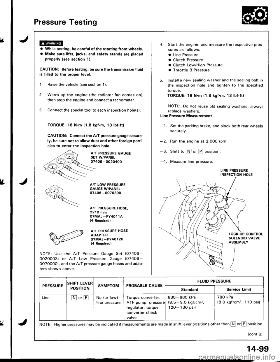
Pressure Testing
a While testing, be careJulot the rotating front wheels.
a Make sule litts, iacks, and safety stands are placed
properly (see section 1).
CAUTION: Befoie testing, be sure the transmission fluid
is filled to the proper level.
'1. Raise the vehicle {see section 'll.
2. Warm up the engine (the radiator fan comes on),
then stop the engine and connect a tachometer.
3. Connect the special tool to each inspection hole(s).
TOROUE: 18 N.m l1-8 kgt.m, 13lbf.ftl
CAUTION: Connect the A/T pressure gauge secure-
ly, be sure not to allow dust and olher foreign pani-
cles to enter the inspection hole.
A/T PRESSURE GAUGESET W/PANEL07406 -0020400
A/T LOW PRESSUREGAUGE W/PANEI.07406-OO70300
A/T PRESSURE HOSE,2210 mmOTMAJ _PY4O1 1A{4 Required}
A/T PRESSURE HOSEADAPTER07MAJ -PY40120
l4 Requiredl
NOTE: Use the A/T Pressure Gauge Set (07406-
OO2O0O3) or A/T Low Pressure Gauge (07406-
OOTOOOO), and the A/T pressure gauge hoses and adap-
ters shown above.
4. Start the engine, and measure the respective pres
sures as follows.
a Line Pressure
a Clutch Pressure
a Clutch Low/High Pressure
a Throttle B Pressure
5. Install a new sealing washer and the sealing bolt in
the inspection hole and tighten to the specified
torque.
TOROUE:18 N.m (1.8 kgf.m, 13lbf.ft)
NOTE: Do not reuse old sealing washers; alwaysreplace washers.
Line Pressure Measurement
-1. Set the parking brake, and block both rear wheels
securely.
-2. Run the engine at 2,000 rpm
3. Shift to S or @ position.
4. lMeasure line pressure.
LINE PRESSUREINSPECTION HOLE
LOCK-UP CONTROLSOLENOID VALVEASSEMBLY
PRESSURESHIFT LEVER
POST ONSYMPTOMPROBABLE CAUSEFLUID PRESSURE
StandardService Limit
LineNo,BNo (or low)
Irne pressure
Torque converter,
ATF pump, pressure
regulator, torque
converter check
830 88o kPa
(8.5 9.O kgf/cm'�,
1 20 130 psi)
78O kPa(8.O kgf/cm'�, 1 10 psi)
NOTE: Higher pressures may be indicated if measurements are made in shitt lever positions other than S or f, position.
{cont'd )
14-99