key HONDA INTEGRA 1998 4.G Owner's Manual
[x] Cancel search | Manufacturer: HONDA, Model Year: 1998, Model line: INTEGRA, Model: HONDA INTEGRA 1998 4.GPages: 1681, PDF Size: 54.22 MB
Page 1207 of 1681
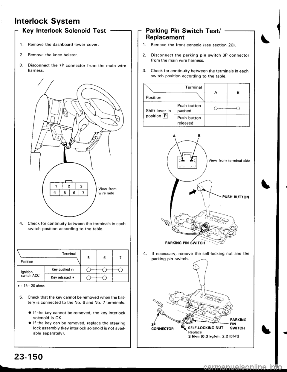
Interlock System
Key Interlock SolenoidTest
1. Remove the dashboard lower cover.
2. Remove the knee bolster.
3. Disconnect the 7P connector from the main wireharness.
Check for continuity between the terminals in each
switch position according to the table.
5. Check that the key cannot be removed when the bat-
tery is connected to the No. 6 and No. 7 terminals.
a lf the key cannot be removed, the key interlock
solenoid is OK.
a lf the key can be removed, replace the steering
lock assembly (key interlock solenoid is not avail-
able separately).
\_____,___ ___l
PositionJ7
lqnitions-wirch ACC
Key plshed inG---o
Key released *o---o
* : 15 - 20 ohms
,l
\,
Parking Pin Switch Test/
1.
2.
Replacement
3.
Remove the lront console (see section 20).
Oisconnect the parking pin switch 3P connector
from the main wire harness.
Check Ior continuity between the terminals in each
switch position according to the table.
lf necessary, remove the self-locking nut and the
parking pin switch.
PARKINGPINSELF'LOCKINGNUT SWITCHReplace3 N.m {0.3 kgf.m,2.2 lbf.ft)
Terminal
,o"n*
-- ---_\B
Shitt lever in
position @
Push button
pusneoo-----o
Push button
reteaseo
Page 1209 of 1681
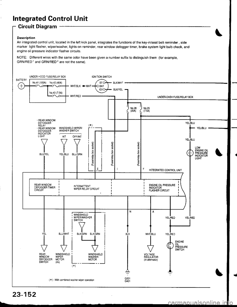
Integrated Control Unit
Circuit Diagram
Description
An integrated control unit, located in lhe left kick panel, integrates the lunctions of the key-in/seat belt r€minder , side
marker light llasher, wiper/washer, lights-on reminder, rear window delogger timer, brake system light bulb check, and
engine oil pressure indicator flasher circuits.
NOTE: Different wires with the same color have been given a nu mber suflix to distinguish them (for example,
GRN/RED I and GRN/RED'� are not the same).
REAR WINDOWDEFOGGERRELAYREAF WINDOWDEFOGGENIND CATORL GHT
f-7
IIBLU/YEL
WHT/ BLK
WHT/ REO
+WHT
WNDSHIELDWIPERiWASHER SWITCH
INT OFF/INT
f7 f7
tltlYEUBLU 8LU/GRN
BLUMHT
J
wtN0sHr€10WIPERMOTOR
UNDER.DASH FUSARETAY BOX
F rmecnlleo counoL ultr
YEUBLU
rYEUBLU
YEUREO YEUREO
tl
IYEURED
LOWENGINEOIIPRESSUREINOICATOBLIGHT
; WINDSHIELD' WIPERMASHERI swlTcH
tf7IVtlYEL
J
FEARwtN00wOEFOGGERSWITCH
WHTIBLU
J
VOTTAGEREGULATOR(ln allernatol)
BLK
G441
ENGINEolLPRESSUREswrTcH
UNDER-NOOO FUSE/RELAY BOX
1.6
:6
t;t-L
i
"'i'- 'i*-
|
I Il
I vi: WINDSHIELO II WASHEB I
L__ "oto: _ __l(*)
n
s
s
,]
23-152
(*) :Wilh combined washer-wiper operalion
Page 1213 of 1681
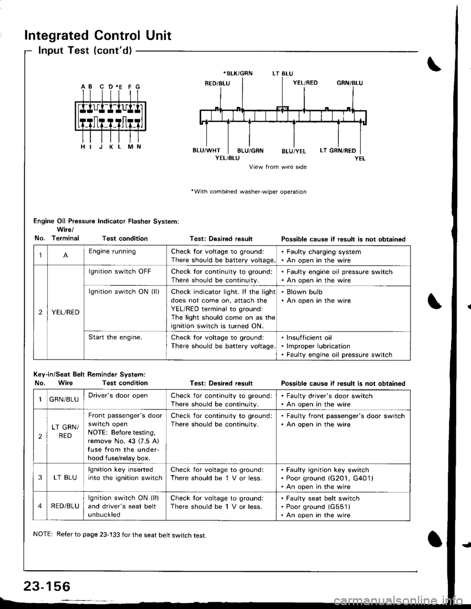
Integrated Control Unit
lnput Test (cont'd)
YEL/BLU
View from wire side
'With combined washer-wiper operation
Engine Oil Pressure Indicator Flasher System:
Wire/
No. TerminalTest condition
Key-in/Seat Belt Reminder System:
No. WileTest condition
Testi Desired result
Test: Desired result
Possible cause if result is not obtainsd
Possible cause if fesult is not obtained
*BLK/GRN
1Engine runningCheck for voltage to ground:
There should be battery voltage.
. Faulty charging system. An open in the wire
2YEL/RED
lgnition switch OFFCheck for continuity to ground:
There should be continuity.
. Faulty engine oil pressure switch. An open in the wire
lgnition switch ON (ll)Check indicator light. It the light
does not come on, attach the
YEL/RED terminal to groundl
The light should come on as the
ignition switch is turned ON.
. Blown bulb. An open in the wire
Start the engine.Check tor voltage to ground:
There should be battery voltage
lnsufticient oil
lmproper lubrication
Faulty engine oil pressure switch
1GRN/BLUDriver's door openCheck for continuity to ground:
There should be continuity.
. Faulty driver's door switch. An open in the wire
2
LT GRN/
RED
Front passenger's door
swrlcn open
NOTE: Before testing,
remove No. 43 {7.5 A)
fuse from the under-
hood fuse/relay box.
Check for continuity to ground:
There should be continuity.
. Faulty front passenger's door switch'An open in the wire
3LT BLU
lgnition key inserted
into the ignition switch
Check for voltage to ground:
There should be 1 V or less.
Faulty ignition key switch
Poor ground (G2O1, G401 l
An open in the wire
4RED/BLU
lgnition switch ON (lll
and driver's seat belt
unbuckled
Check for voltage to ground:
There should be 1 V or less.
Faulty seat belt switch
Poor ground (G551l
An open in the wire
NOTE: Refer to page 23-133 for the seat belt switch test.
Page 1215 of 1681
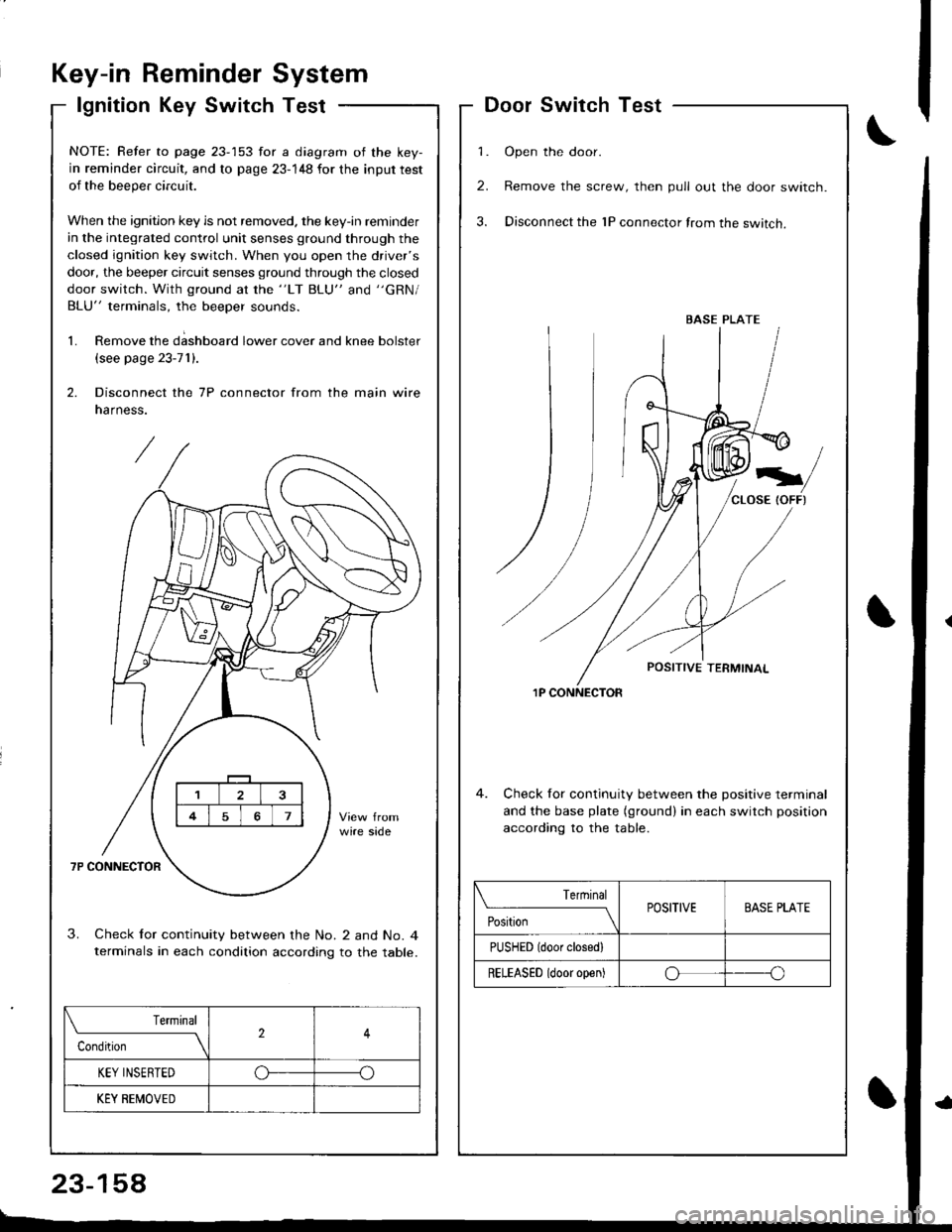
Key-in ReminderSystem
lgnition Key SwitchTest
\f
DoorSwitchTest
1. Open the door.
2. Remove the screw, then pull out the door switch.
3. Disconnect the 1P connector from the switch.
1P CONNECTOR
4. Check for continuity between the positive terminal
and the base plate (ground) in each switch position
accordinq to the table.
BASE PLATE
Terrninal
PositionPOSITIVEBASE PLATE
PUSHED (door closedl
RELEASED (door open)oo
NOTE: Refer to page 23-153 for a diagram of the key-
in reminder circuit, and to page 23-148 for the input test
of the beeper circuit.
When the ignition key is not removed. the key-in reminder
in the integrated control unit senses ground through the
closed ignition key switch. When you open the driver's
door, the beeper circuit senses ground through the closed
door switch. With ground at the "LT BLU" and "GRN/
BLU" terminals, the beeper sounds.
1. Remove the d;shboard lower cover and knee bolster
(see page 23-71).
2. Disconnect the 7P connector from the main wire
narness.
3. Check lor continuity between the No. 2 and No. 4terminals in each condition according to the table.
Terminal
Condition2
KEY INSERTEDo--o
KEY BEMOVED
23-158
Page 1296 of 1681
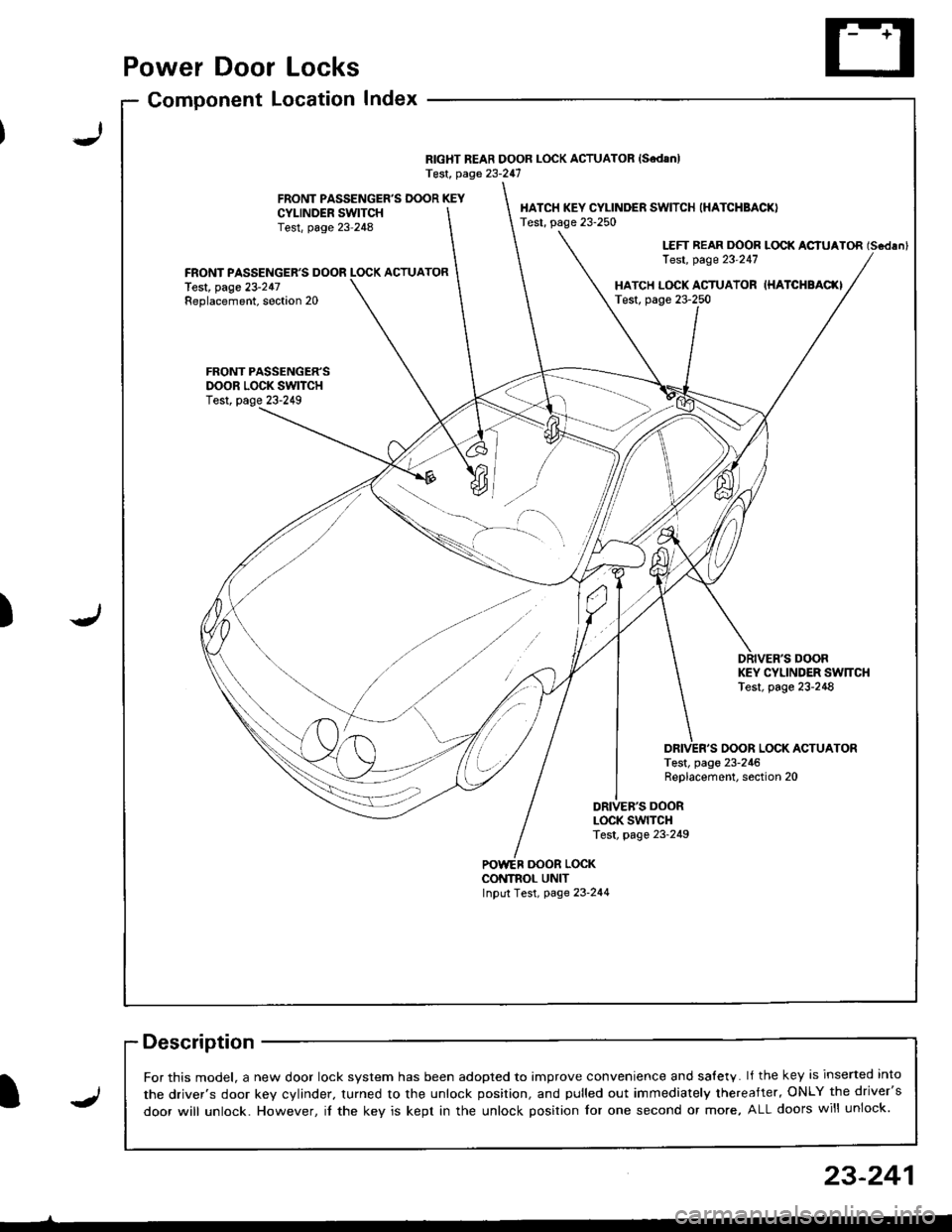
Power Door Locks
Component LocationIndex
RIGHT REAR DOOR LOCK ACTUATOR {SedanlTest, page 23-247
FRONT PASSENGER'S DOOR KEYCYI-INDER SWITCHTest, page 23-248
HATCH KEY CYLINDER SWITCH (HATCHBACK)
Test, page 23-250
LEFT REAR DOOR LOCK ACIUATOR (Scdlnl
Test, page 23'247FRONT PASSENGER'S DOOR LOCK ACTUATORlest, page 23-247Replacement, soction 20HATCH L(rcK ACTUATOR IHATCHBAC(ITest, page 23-250
FRONT PASSENGER'SDOOR LOCK SWITCHTest, page 23-249
DRIVER'S DOORKEY CYLINDER SW]TCHTest, page 23-248
OOOR LOCK ACTUATORTest, page 23-246Replacement, section 20
DRIVEB'S DOORLOCK SWITCHTest, page 23-249
oooR LocKCONTNOL UNITInput Test, page 23-244
-)
J)
I
For this model, a new door lock svstem has been adooted to imDrove convenience and salety. lf the key is inserted into
the driver's door kev cvlinder. turned to the unlock position, and pulled out immediately thereafter, ONLY the driver's
door will unlock. However, il the key is kept in the unlock position for one second or more, ALL doors will unlock.J
23-241
Page 1297 of 1681
![HONDA INTEGRA 1998 4.G Owners Manual Power Door Locks
Circuit Diagram
@*"
DR]VERS000R LocKSWITCH
NATCN KEYCYLINDER SWITCH
L_____
ooon rocx xroe If7 l
VIKEY
DRIVERSDOOR LOCKACTUATOR
E
UNDER.HOOO FUSEi RELAY BOX
N0.41 (1004) No.s4 (40A)
HONDA INTEGRA 1998 4.G Owners Manual Power Door Locks
Circuit Diagram
@*"
DR]VERS000R LocKSWITCH
NATCN KEYCYLINDER SWITCH
L_____
ooon rocx xroe If7 l
VIKEY
DRIVERSDOOR LOCKACTUATOR
E
UNDER.HOOO FUSEi RELAY BOX
N0.41 (1004) No.s4 (40A)](/img/13/6069/w960_6069-1296.png)
Power Door Locks
Circuit Diagram
@*"
DR]VER'S000R LocKSWITCH
NATCN KEYCYLINDER SWITCH
L_____
ooon rocx xroe If7 l
VIKEY
DRIVER'SDOOR LOCKACTUATOR
E
UNDER.HOOO FUSEi RELAY BOX
N0.41 (1004) No.s4 (40A)
DFIVERS DOORKEY CYLJNOERSWITCH
WHT/GRN
FRONTPASSENGERSDOOR LOCKACTUATOR
T--=-l-4{il^
* LEFT REARDOOR LOCKACTUATOR
,@-
* RIGHT NEARDOOR LOCKACTUATOH
-4{.ill^
HATCH LOCKACTUATOR
T-:-lfl.|.{-
LTGRN
LT BLU
A
t--lt=JKEY
i
Atl
T-tl-lKEYBLK
I
G503
.LK BLKll
tlAA
:-l
G501 G2r.G502 ercl
BLK
,l'
G5o1G502
LOCK
o
POWER DOORLOCK CONTROLUNIT
8LK
A-l
G501G502
23-242
Page 1298 of 1681
I,t
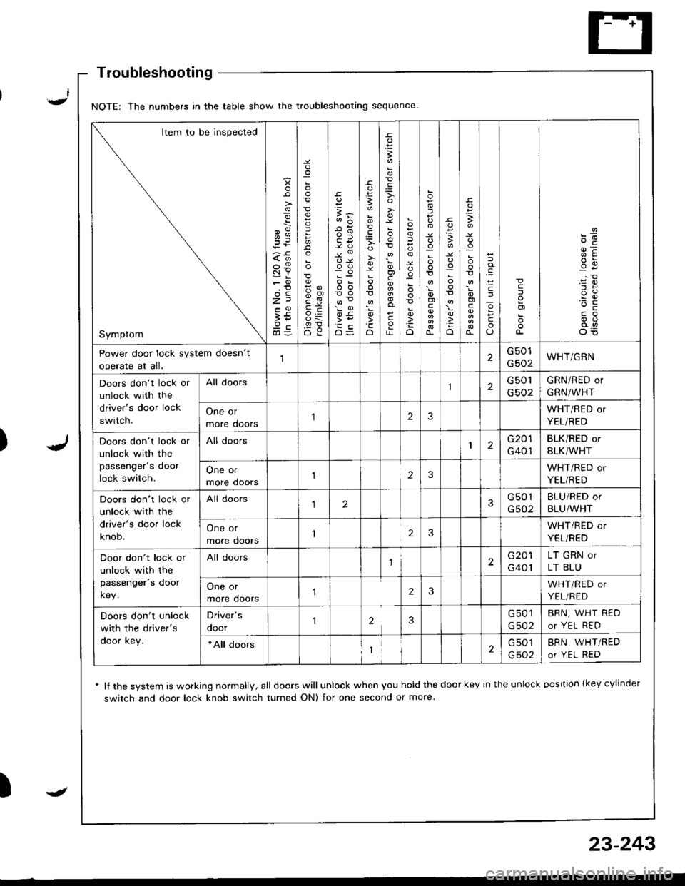
Troubleshooting
* lf the system is working normally, all doors will unlock when you hold the door key in the unlock oosrtion {key cylinder
switch and door lock knob switch turned ON) for one second or more
)
NOTE: The numbers in the table show the troubleshooting sequence
Item to be inspected
Symptom
g
;i
:
5
{,!
(,o
o-c
E5
B
'io
B
o)c
c
o
:
D
.uo
I
o)
o-
-c
:o
o
I
!
o)
cJ
o
c
c
o)
Power door lock system doesn't
operate at all.
G501
G502WHT/GRN
Doors don't lock or
unlock with the
driver's door lock
switch.
All doors2G 501
G502
GRN/RED or
GRN/WHT
One or
more doors
'I23WHT/RED or
YEL/RED
Doors don't lock or
unlock with the
passenger's door
lock switch.
All doors1G201
G401
BLK/RED or
BLK/WHT
One or
more ooors123WHT/RED or
YEL/RED
Doors don't lock or
unlock with the
driver's door lock
knob.
All doors123G501
G502
BLU/RED or
BLU/WHT
One or
more doors123WHT/RED or
YEL/RED
Door don't lock or
unlock with the
passenger's door
key.
All doorsl2G201
G401
LT GRN or
LT BLU
One or
more doors2WHT/RED or
YEL/RED
Doors don't unlock
with the driver's
door key.
Driver's
ooor23G501
G502
BRN, WHT REO
or YEL RED
*All doors1G 501
G502
BRN, WHT/RED
or YEL RED
-
23-243
Page 1300 of 1681
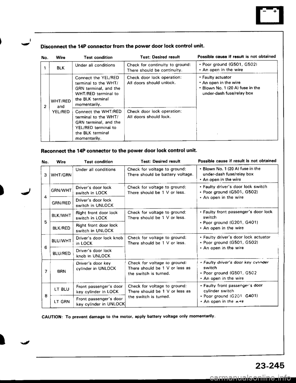
Disconnect the 14P connector from the power door lock control unit'
)
No. WileTest conditionTest: Dgsired resultPossible causo if rosult is not obtained
Reconnect the 14P conneetor to the power door lock control unit'
No. wireTest conditionTest: Desired resultPossible cause il result is not obtained
I
1BLKUnder all conditionsCheck tor continuity to ground:
There should be continuity.
. Poor ground (G50'1, G502). An open in the wire
2
WHTi RED
ano
YEL/RED
connect the YEL/RED
terminal to the WHT/
GBN terminal, and the
WHT/RED terminal to
the BLK terminal
momentarily.
Check door lock operation:
All doors should unlock.
Faulty actuator
An open in the wire
Blown No. 1 {20 A} fuse in the
under-dash Juse/relay box
Connect the WHT/RED
terminal to the WHT/
GRN terminal, and the
YEL/RED terminal to
the BLK terminal
momentanly.
Check door lock operation:
All doors should lock.
3WHT/GRN
Under all conditionsCheck for voltage to ground:
There should be battery voltage.
. Blown No. 1 (20 A) fuse in the
under-dash fuse/relay box. An open in the wire
GRN/WHTDriver's door lock
switch in LOCK
Check lor voltage to ground:
There should be 1 V or less.
Faulty driver's door lock switch
Poor ground (G501, G502)
An open in the wire
GRN/REDDriver's door lock
switch in UNLOCK
5
BLK/WHTRight front door lock
switch in LOCK
Check for voltage to ground:
There should be 1 V or less.
Faulty front passenger's door lock
switch
Poor ground (G201 , G401)
An open in the wireBLKi REDRight front door lock
switch in UNLOCK
BLU/WHTDriver's door lock knob
in LOCK
Check for voltage to ground:
There should be 1 V or less.
. Faulty driver's door lock actuator. Poor ground (G501, G502). An open in the wire
BLU/REDDriver's door lock
knob in UNLOCK
7BRN
Oriver's doo. key
cylinder in UNLOCK
Check for voltage to ground:
There should be 1 V or less as
the switch is turned.
. Faulty driver's door key cvtrrder
switch. Poor ground (G501, G502. An open in the wire
8
LT BLUFront passenger's door
key cylinder in LOCK
Check for voltage to ground:
There should be 1 V or less as
the switch is turned.
. Faulty front passengef's door
cylinder switch. poor ground lG20r G4Ol). An open in the *reLT GRNFront passenger's door
key cylinder in UNLOCK
\J
CAUTION: To prevent damage to the motol, apply battery voltage only momentarily
23-245
Page 1303 of 1681
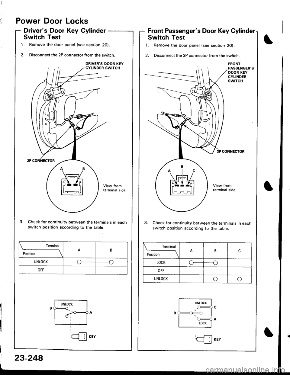
Power Door Locks
Driver's Door Key Cylinder
Switch Test
1. Remove the door panel (see section 20).
2. Disconnect the 2P connector f.om the switch.
terminal side
Check tor continuity between the terminals in eachswitch position according to the table.
Front Passenger's Door Key Cylinder
Switch Test
1. Remove the door panel (see section 20).
2. Disconnect the 3P connector from the switch.
FRONTPASSENGER'SDOOR KEYCYLINDERSwlTCH
CONNECTOR
3. Check for continuity between the terminals in eachswitch position according to the table.
Terminal
il;------__\tt
UNLOCKoo
OFF
Terminal
P**--__\c
LOCKo--o
UNLOCKoo
UNTOCK<
I
UNLOCK
r--O\:
I LOCK
23-248
(--l__!J KEYtil
Page 1305 of 1681
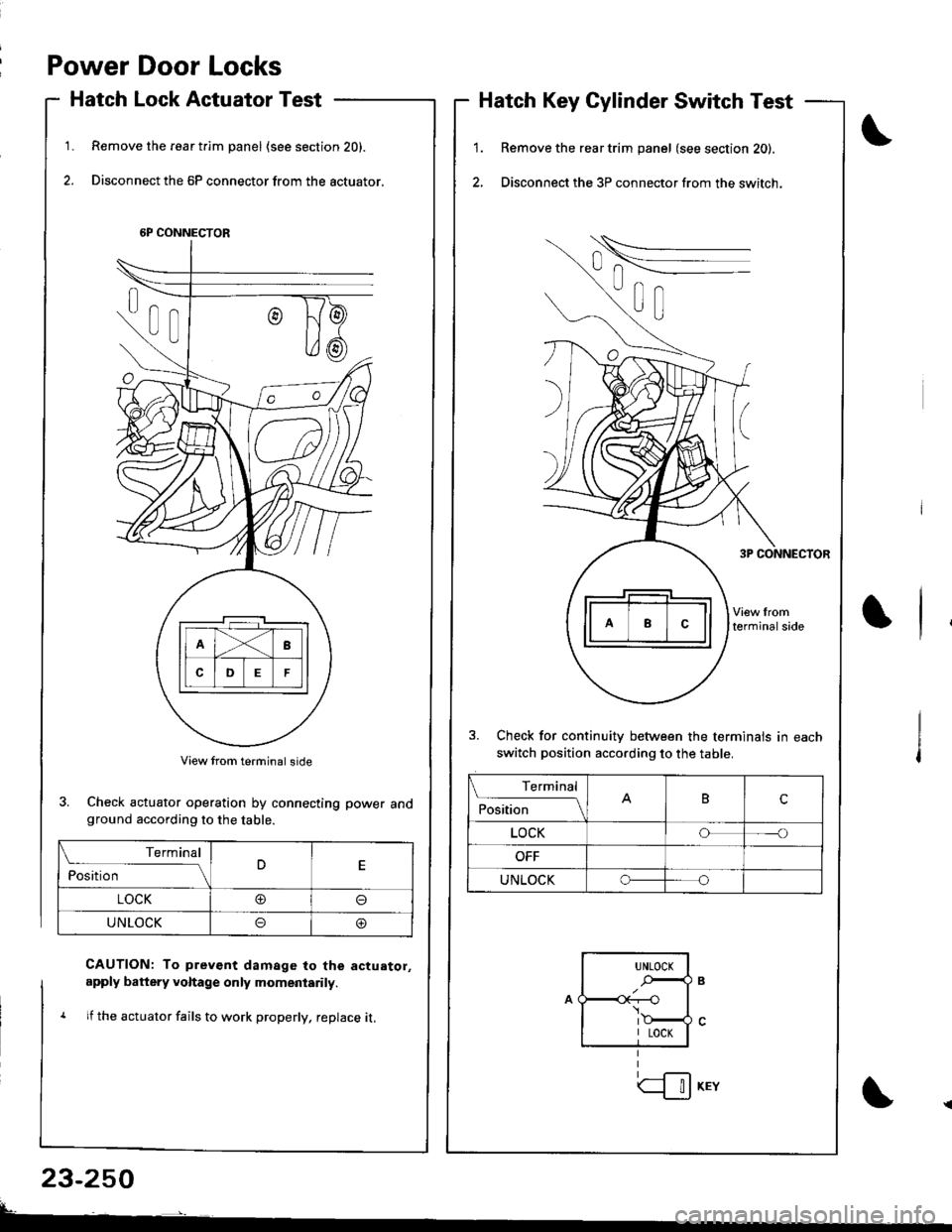
Power Door Locks
Hatch Lock Actuator Test
Remove the rear t.im panel (see section 20).
Disconnect the 6P connector from the actuator.
1.1.
2.
Hatch Key Cylinder Switch Test
Remove the rear trim panel (see section 20).
Disconnect the 3P connector from the switch.
3. Check for continuitv between the terminals in each
switch position according to the table.
6P CONNECTOR
3. Check actuator operation by connecting power andground according to the table.
CAUTION: To prev€nt damage to the actuator,
apply battery voltage only momeniarily.
1 lf the actuator fails to work properly, replace it,
23-250
Terminal
ilil;---tBc
LOCKoo
UNLOCKo
Terminal
ilil;-]E
LOCK@o
UNLOCKoo
UNLOCK
.-,4
I LOCK
| !J KEY