key HONDA INTEGRA 1998 4.G Owner's Guide
[x] Cancel search | Manufacturer: HONDA, Model Year: 1998, Model line: INTEGRA, Model: HONDA INTEGRA 1998 4.GPages: 1681, PDF Size: 54.22 MB
Page 1306 of 1681
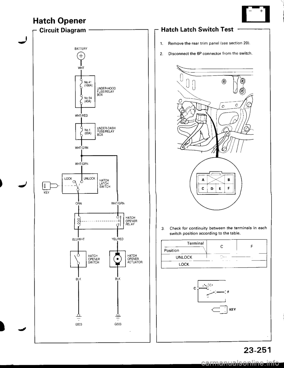
Hatch Opener
Circuit DiagramHatch Latch Switch Test
Remove the rear trim panel lsee section 20).
Disconnect the 6P connector from the switch.
3. Check for continuity between the terminals in each
switch position according to the table.
HATCHOPENEHRELAY
HATCHOPENERACTUATOB
UNDER-HOODFUSE/RELAYBOX
UNDER.DASHFUSE/RELAYBOX
la :llf q ^ll
ELUMHT YEURED
tl
[S-l*0,., f/tl| IoPENEF lt.l I
I ? l'*n'" +_i
tl8LK BLK
tl
tl
tt.:
G503 G503
BATTEFY
(+)
Y
I
-r--t
I I lm,1
uI| )Nov II f. (4oA) |rT '
IWHT/RED
I-r----| )ur II L (2oA) I
IWHTiGRN
fi--l->t_:___J-KEY
Terminal
:- ..- crosrUon-1UNLOCK
LOCK
F
23-251
-----t1< IKEY--,_)
J
Page 1340 of 1681
Precautions/Procedures
Steering-related Precautions
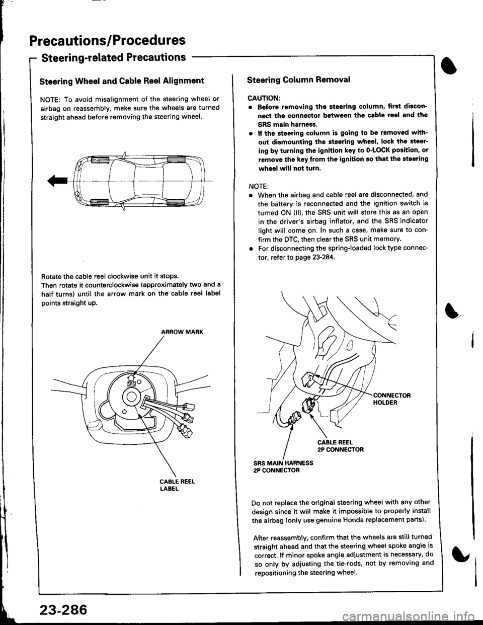
Steering Wheel and Gable Reel Alignment
NOTE: To avoid misalignment of the steering wheel or
airbag on reassembly. make sure the wheels are turned
straight ahead before removing the steering wheel.
Rotate the cable reel clockwise unit it stops.
Then rotate it counterclockwise (approximately two and a
half turns) until the arrow mark on the cable reel label
points straight up.
ARROW MARK
23-286
Steering Column Removal
CAUTION:
. Before romoving the steoring column, lirst di3con-
nect ths connector bctwoen tho csble rsal and the
SBS main harneEs.
. lf the steeting column is going to be rsmoved with-
out dismounting the steering wheel, lock the steer-
ing by iurning the ignition k6y to o'LOCK position' or
remove tho key lrom thc ignition ro that the steering
wheel will not turn.
NOTE:
When the airbag and cable reel are disconnected, and
the battery is reconnected and the ignition switch is
turned ON (ll), the SRS unit will store this as an open
in the driver's airbag inflator, and the SRS indicator
light will come on. In such a case, make sure to con-
firm the DTC, then clear the SRS unit memory.
For disconnecting the spring-loaded lock type connec-
tor, refer to page 23-284,
SRS MAIN HARNESS2P CONNECTOR
Do not replace the original steering wheel with any other
design since it will make it impossible to properly install
the airbag {only use genuine Honda replacement parts).
After reassembly. confirm that the wheels are still turned
straight ahead and that the steering wheel spoke angle is
correct, lf minor spoke angle adjustment is necessary, do
so only by adjusting the tie-rods, not by removing and
repositioning the steering wheel.
L
Page 1383 of 1681
).1
Contents
How to Use This l\.4anual 1Circuit Schematics (see Circuit Index)Fuse/Relaylnformation 6ComponentLocation Photographs 201
Connector Cavity Numbers 202Connectorldentification 203
Ground-to-Components Index 6-6Wire Harness Routing 203Circuit ldentification lor ln-Line and Fuse Box Connectors
Circuit Index
Air conditionerAir delivery 61Blower controls 60Compressor controls 62Fans 63Anti-lock brake system (ABS) 44A/T gear position indicator 89Automatic transmission controls'98199 models 39'00 models 39-4Back-up lightsHatchback 110Sedan 110- 1Brake system indicator light
USA 71Canada 71-1Brake lightsHatchback 110-6Sedan 110-7Cargo area light (Hatchback) 114-3Ceiling light 114-2Charging system 22Cigarette lighter 155
Clock 154Condenser fan 63Console lights 114Cruise control 34Dash lights 1 14Daytime running lights 110-8Door open indicator 114-2Engine coolant temperature gauge 81Engine oil pressure indicator light 72Fog lights 110-14Front parking lights 110-11Front side marker lights 110-11Fuel gauge 81Fuse/relay boxUnder-dash 6Under-hood 6-3Under-hood ABS 6-5Gauges 81Glove box light 114Ground distribution 14Ground-to-Componentsindex 6-6Hatch open indicator '114-3
Hatch opener '134
Hazard warning lightsHatchback 'l l0-2Sedan 110-4Headlights 1'10-8Headlight switch 100HeaterAir delivery 61Blower controls 60Fanswith A,/C 63without A,/C 63-2Horns 40lgnilion key reminder 73lgnition system 20
204
lmmobilizer system ('00 model) 132lndicators 80Integrated control unit 70Interlock system'98199 models 138'00 models 138-1License plate lightsHatchback 110-12Sedan 110-13Lights-on reminder 73Low fuel indicator light 74l\,4aintenance reminder light 83l\iloonroof 122Odometer 81-1Power antenna 151Power distributionBattery to ignilion switch, fuses, and relays
Fuses to relays and components 10-2Power door locksHatchback '130
Sedan 130-2Power mirrorsHatchback 141Sedan 141-1Power windowsHatchback 120Sedan 120-2Programmed fuel injection system (PGM-Fl)'98199 models 23'00 models 24Radiator fanwith tuC 63without A,/C 63-2Rear parking lightsHatchback 110-12Sedan 110- 13Rear window defogger 64Seat belt reminder 73Security system 133Speedometer Il-1Spotlights 114-2Starting syslemAutomalictransmission 21l\.4anualtransmission 21-1Stereo sound system 150Supplemental restraint system (SRS) 47Tachometer 81- 1TaillightsHatchback 110-12Sedan 110-13Trailer lighting conneclor 118Trunk lid open indicator 114-3Trunk light (Sedan) 114-3Turn signal lightsHatchback 110-2Sedan 110-4Vehicle speed sensor (VSS) 33Wiper/washerFront 91Rear 92
10
).1
I
Xr
12Fg oAmerican Honda Motor Co., Inc. - All Rights Reserved Service Communications 275 pages
Page 1394 of 1681
'l'
Five-Step Troubleshooting
1. Verify The Complaint
Turn on all the components in the problem
circuit to check the accuracy of the customer
complaint. Note the symptoms. Do not begin
disassembly or testing until you have
narrowed down the Problem area.
2. Analyze The Schematic
Look up the schematlc for the problem
circuit. Determine how the circuit is
supposed to work by tracing the current
paths from the power source through the
circuit components to ground. Also, trace
circuits that share wiring with the problem
circuit. The names of circuits that share the
same fuse, ground, or switch, and so on' are
referred to in each circuit schematic. Try to
operate any shared circuits you didn't check
in steo 1. lf the shared circuits work, the
shared wiring is OK, and the cause must be
in the wiring used only by the problem
circuit. lf several circuits fail at the same
time, the fuse or ground is a likely cause.
Based on the symptoms and Your
understanding of the circuit's operation,
identify one or more possible causes.
3. lsolate The Problem By Testing The Circuit
Make circuit tests to check the diagnosis
you made in step 2. Keep in mind that a
logical, simple procedure is the key to
eff icient troubleshooting. Test for the most
likely cause of failure f irst. Try to make tests
at points that are easily accessible.
4. Fix The Problem
Once the specific problem is identified,
make the repair. Be sure to use proper tools
and safe procedures.
5. Make Sure The Circuit Works
Turn on all components in the repaired
circuit in all modes to make sure you've
fixed the entife problem. lf the problem was
a blown f use, be sure to test all of the
circuits on that {use. Make sure no new
problems turn up and the original problem
does not recur.
Test Equipment
CAUTION:
Most circuits include solid-state devices.
Test the voltages in these circuits only with
a 1o-megaohm or higher impedance digital
multimeter. Never use a test light or analog
meter on citcuits that contain solid-state
devices. Damage to the devices may result.
Test Light and DVOM
On circuits without solid-state devices, use a
test light to check for voltage. A test light is
made up of a 12 volt bulb with a pair of leads
attached. After grounding one lead, touch the
other lead to various points along the circuit
where voltage should be present. The bulb
will go on i{ there is voltage at the point being
tested. lf you need to know how much
voltage is present, use a digital
volVohmmeter (DVOM).
Selt-Powered Test Light and DVOM
Use a self-powered test light to check for
continuity. This tool is made up of a light bulb,
battery, and two leads. To test it, touch the
leads together: the light should go on.
Use a self-powered test light only on an
unoowered circuit. First, disconnect the
battery, or remove the fuse that feeds the
circuit you are working on. Select two points
in the circuit between which you want to
check continuity. Connect one lead ol the
self-powered test light to each point. lf there
is continuity, the test light's circuit will be
completed, and the light will go on.
lo
I
SELF.POWERED TEST LIGHT
Page 1406 of 1681
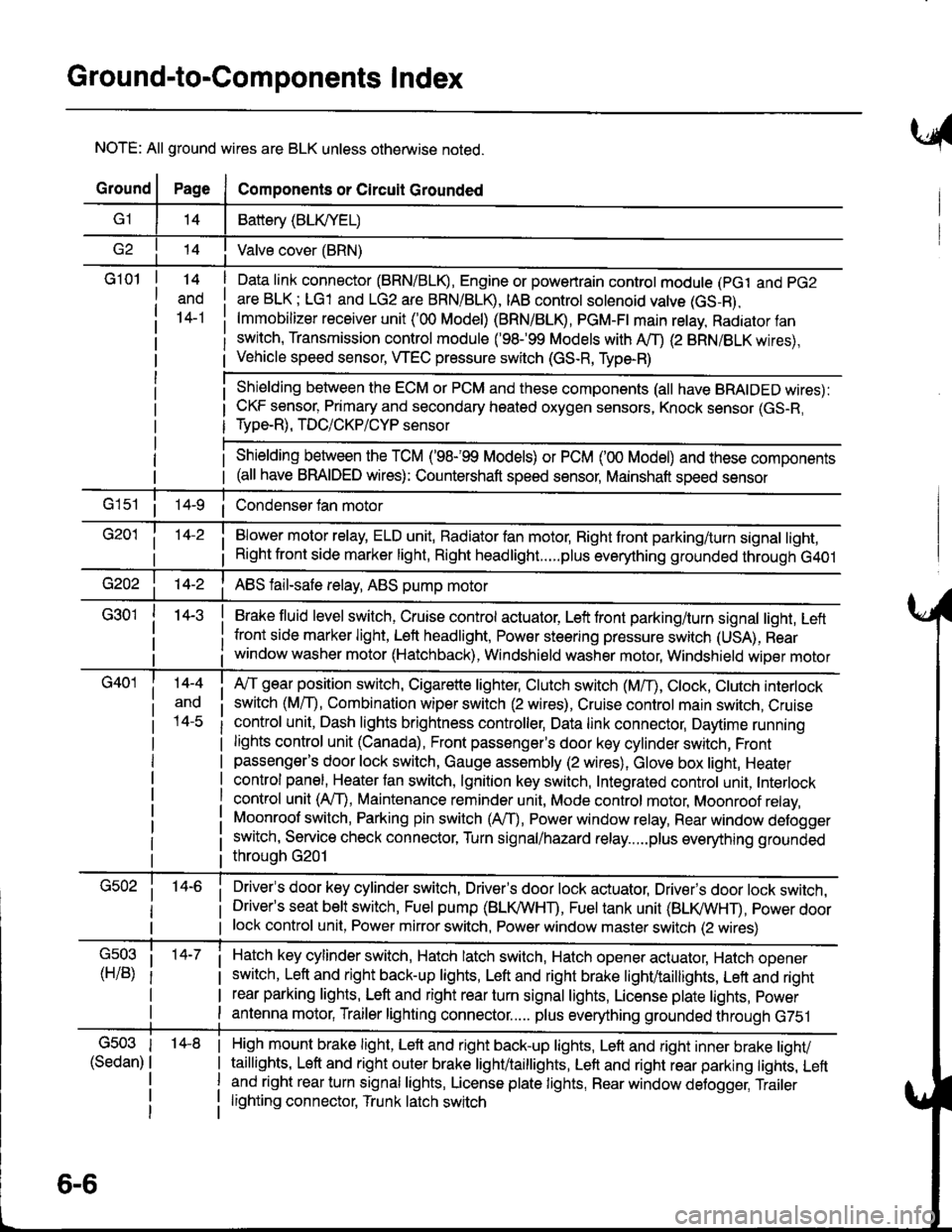
Ground-to-Components I ndex
NOTE: All ground wires are BLK unless otherwise noted.
GroundPageComponents or Circuit Grounded
Battery (BLIVYEL)
--t'I Valve cover (BRN)
G101t.+
and
14-1
Daia link connector (BRN/BLK), Engine or powertrain controt module (pct and pG2
are BLK; LG1 and LG2 are BRN/BLR, IAB controt solenoid valve (GS-B),
lmmobilizer receiver unit ('00 Model) (BRN/BLR, PGM-Ft main retay, Radiator fan
switch, Transmission control module ('98.�99 Models with MD (2 BRN/BLK wires),
Vehicle speed sensor, WEC pressure switch (GS-R, Type-R)
Shielding between the ECM or PCM and these components (all have BRAIDED wires):
CKF sensor, Primary and secondary heated oxygen sensors, Knock sensor (GS-R,
Type-R), TDC/CKP/CYP sensor
Shielding between the TCM ('98-'99 Models) or PCM ('00 Model) and these components(all have BRAIDED wires): Countershaft speed sensor, Mainshaft speed sensor
G1s1 ii Condenser fan motor
Brake fluid level switch, Cruise control actuator, Left front parking/turn signal light, Left
front side marker light, Left headlight, Power steering pressure switch (USA), Rear
window washer motor (Hatchback), Windshield washer motor, Windshield wiper motor
14-3
Blower motor relay, ELD unit, Badiator fan motor, Right front parking/turn signal light,
Right front side marker light, Right headlight.....plus everything grounded through G401
ABS fail-safe relay, ABS pump motor
G40114-4
ano
l4-c
A,/T gear position switch, Cigarette lighter, Clutch switch (M,/T), Ctock, Ctutch interlock
switch (MfD, Combination wiper switch (2 wires), Cruise control main switch, Cruise
control unit, Dash lights brightness controller, Data link connector, Daytime running
lights control unit (Canada), Front passenger's door key cylinder switch, Frontpassenger's door lock switch, Gauge assembly (2 wires), Glove box light, Heater
control panel, Heater tan switch, lgnition key switch, Integrated control unit, Interlock
control unit (AfI), Maintenance reminder unit, Mode control motor, Moonroof relay,
Moonroof switch, Parking pin switch (AfD, Power window relay, Rear window defogger
switch, Service check connector, Turn signal/hazard relay.....plus everything grounded
throuoh G201
Driver's door key cylinder switch, Driver's door lock actuator, Drivels door lock switch,Driver's seat belt switch, Fuel pump (BLI(/WHT), Fuel tank unit (BLI(/WHT), power doorlock control unit, Power mirror switch, Power window master switch (2 wires)
Hatch key cylinder switch, Hatch latch switch, Hatch opener actuator, Hatch ooener
switch, Left and right back-up lights, Left and right brake light/taillights, Lett and right
rear parking lights, Left and right rear turn signal lights, License plate lights, power
antenna motor, Trailer lighting connector..... plus everything grounded through G751
6-6
'14-8G503
(Sedan)
High mount brake light, Left and right back-up lights, Lett and right inner brake tighv
taillights, Left and right outer brake light/taittights, Left and right rear parking tights, Leftand right rear turn signal lights, License plate lights, Rear window detogger, Trailer
lighting connector, Trunk latch switch
Page 1423 of 1681
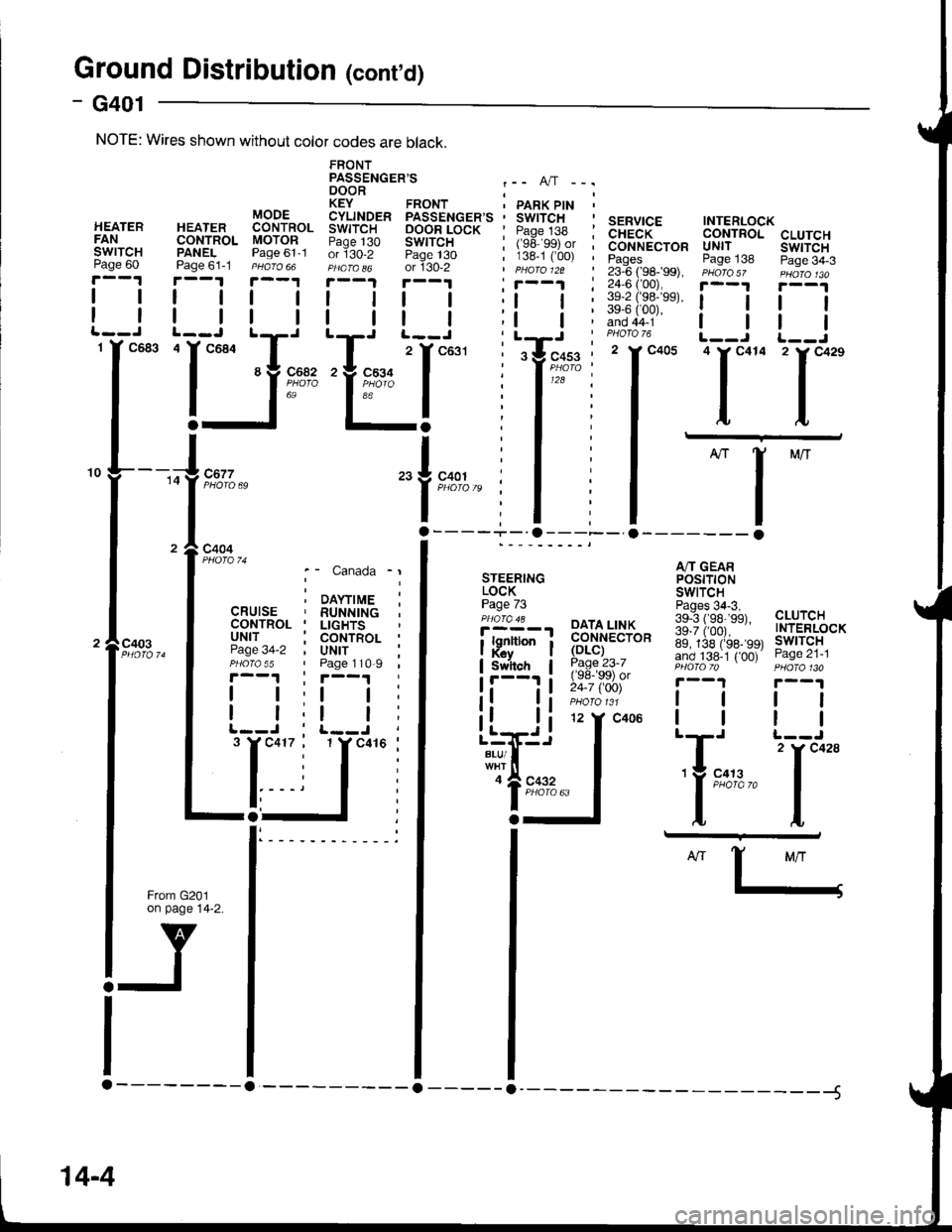
Ground Distributior (cont'd)
- G401
CLUTCHswtTcHPage 34-3
tl
tl
'l**
A/T GEARPOStTTONSWITCH
139""i#;3a, cLUrcH
ig.ii,oor.--" TNTERLOCK
89, 138 (rss- 99t lwlTcHand 138-1 { 00) Page zl-lPHO|OTo PHOfa 130
r--1 r--1
lttl
ttlll-J t--J
| 2 rc428'Y 9:t:,2." I
ttI,L
SERVICE INTERLOCKCHECK CONTROLCONNECTOR UNITPages Page 13823-6 ( 98-�99), PHoro5z24,6 ('00), i--t
iifiii;"' ! !PHOTO 76 L__J'I*- 'l*"
I -
I
-l
ll- o------- o
FRONTPASSENGER'S .-. A,/T -..DOOR ;KEY FRONT ' PARK PtN 'CYLINDER PASSENGER'S ' SWITCHSWITCH OOOR LOCK ' Paqe 138 :Paqe 130 SWITCH I (ge ggt or ior130-2 Page t30 ; 138-1 C00) ,PHafa o6 or 130-2 | pHaro 12a
!.--.! r--1 , r--1 :I | | | ;l | :
| | I | ;t | ;tT' t^-.--i^- , LrJ
"I ^^^-
z
l
t'or' : tY'"*u"" :'Yk91i t ' I'zi :a';"'" I : I
I I :lErl
"1i,.
| .
NOTE: Wires shown without color codes are black.
c403
STEERINGLOCKPage 73'i!Y-', PAIA,LT$
| . i ;;":,;i;
;p,'nron i ffi."ro*Switch I Page 23-7
!'---'' i !i:; iSii'
);
DAYTIMERUNNINGLIGHTSCONTROLUNITPage 110-9
tl
tl
't Y c41(
Canada
\YTIME
Page
I
I12 Y C406
c41
o
a
Llrri.i
i'#!"..,'lgl::""
14-4
Page 1425 of 1681
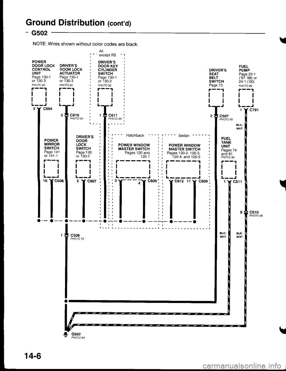
Ground Distribution (conrd)
- Gs02
FUELPUMPPage 23'1('97,'�98) or24 1 ('�00)
tl
tl
98
ORIVER'S PSEAT PiBELT ('IswrTcH 2'page 73 pr
!'--1 7
lll
ttltT' :Tz ! csoz
f
"oto "t
".^
l**' '---- se.ian ------ I
;i rlilFlPOWER WINDOW , f uNtT: : MASTER swtrcH i I F"g"" u+; : Pages 120-2. 120.3. i I ano er120 4. and 120.5 , I photass
':t t;lt I::t l:lt I"L-----J,lL--J
-fl
ll-
' - 31""0, r, - .,
PowER j oRven'sOOOR LOCK DRIVER'S ; DOOR KEY :CONTROL DOOR LOCK , CYLINOER :UNIT ACTUATOR . SWITCHPage 130-1 Page 130-1 : Page 130-1or 130 3 or 130'3 ; or 130-2 :Pnofo u PFofo $ | PtaQfoS5 |r--1 r--1
lttt;tt:
I I I | :t | :
FIFFTo
lTl'lili;-a-- a-- a ---o----a --o----a --
I l._il__-_--
NOTE: Wires shown without color codes are black.
BLlvBLK/c506
! csoz
14-6
Page 1426 of 1681
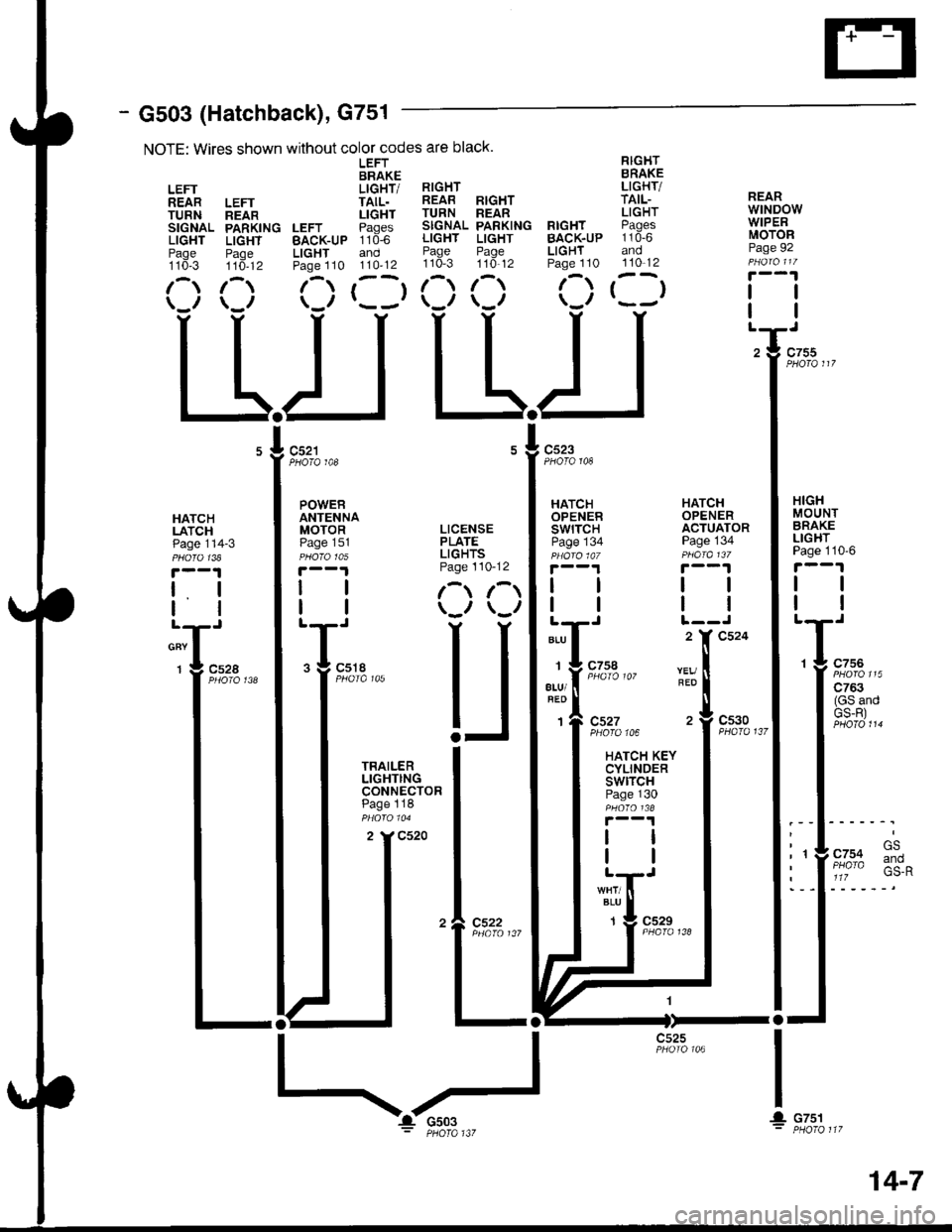
- G503 (Hatchback), G751
NOTE: Wires shown without color codes are black.
LEFT RIGHTBRAKE BRAKE
LEFT LIGHT/ RIGHT LIGHT/
REAR LEFT TAIL. REAB RIGHT TAIL-
TURN neln LIGHT TURN REAR LIGHT
SIGNAL PARKING LEFT Paqes SIGNAL PARKING RIGHT PAgCS
LIGHT LIGHT BAcK-uP 110-6 LIGHT LIGHT BACK.UP 110-6
Paqe Paoe LIGHT and Page Page LIGHT andtto*-s ttd-tz Paoe 110 110'12 110-3 110'12 Page 110 110-12
1-) 1- (-) r--r 1- 1-) f-) t--t(_r \_r \-/ r---' \-,, \-,, \.'/
LLIJ L-L.I
REARwtNDowWIPERMOTORPage 92
tl
PHOTO 108PHOTO 148
HATCHLATCHPage 114-3
t. I
lltl
cnv I
1 g c52a
HATCHOPENERSWITCHPage 134
HATCHOPENERACTUATORPage 134
HIGHMOUNTBRAKELIGHTPage 110'6
tl
tl
1 g c756
| ':::2"'
I (GS andI GS-R)
.l .rl' t- GS
: 'YF/o% :*^I a 1lz
I
IL
ALU
1
atu/
1
REO
c527PHOfO 106
HATCH KEYCYLINDERswtrcHPage 130
c530PHA|O 137
BLU
1c529
I
! cTsl
c525
POWERANTENNAMOTOR LICENSEPaoe 151 PLATEpu6rctos LIGHTS
|.--1 Page 110-12
| | l-t r-t
I | \-., \-,,
T;,. U
I iHi'$t"" I
I :3:.:ll: I
I ^ -:-"^ I
tt*l
tll
I I
'�l e:3?.,,,
ltl-ll-
14-7
Page 1492 of 1681
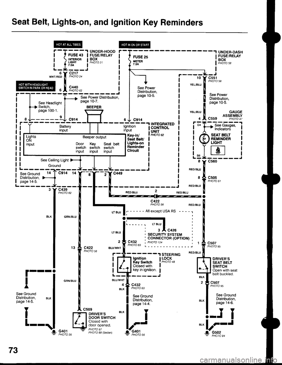
Seat Belt, Lights-on, and lgnition Key Reminders
wHrFEonP,rolo2j
i lll i .._l:["c'xs;"
@,[rsrB", ! | Rtr-r^9,:: I """"1-""
'-----'F--=-'--;fi;'"i
I ffi;'''ffi'' i :seePower
seeHeadriohtf*;ffJiil?l' r i I'l"J:i'J:"t switch. - | BEEPER | | llpage 100-1. | \-7l | | ver-eru I GAUGE
------{ "r'o l-1 . J "r'o i . .I, cuut oss"t"$ElY
! TNTFI:E^TFn I f=tR--
ii
'*:::i"T''*--t
I I ! i
'?tr*aa----'
i t------lI---)t--.&---.L------j i o.o"'u I
i ff{$;{'F1{""0
"l-T-T"*
i
.*r*,
r- - - - - - -
iTs%
-
t
- -
t
- -
f
- - -*"-l
J
- - -
r-
- - -
"'.o ".,
=== = - -
!
Y
I
t
I
See GroundDistribution,page 14-5.
III
i-I+-'.1.1ilg.',8.J39" i-ru;;-
UNDER'DA.H
I rNrEBroR I BOX I
1-l,I:_j
*-"''
i li[::" li[]::'*"
BOXPHOfA 58
i-_I'31_i
,,^sl F,';1",,
| ,1,**",
r----=!i=-'l
F-oc422
----tnilll- -l$H$ffir"
i i'PT:"x':x*
*[-fui'**- i ioiffit.
:i:ltif"i i ilr-zt
! | LeJ-:
LiohtsONinput
Beeper output
Door Key Seat beltswitch switch swiichinput input input
73
II
Page 1543 of 1681
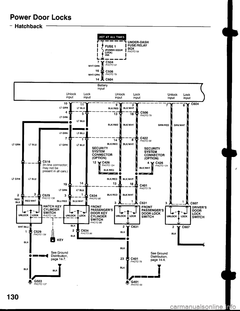
Power Door Locks
- Hatchback
T(
t.x
'o""f "
I
t" lf r8 lf e-l'-d;7o
-: --=--
I ",*".o ! "."*n., ! o"n",,
-l=+------+--,J,*.^
Lrcnr
I
tt "tu
l ar"u*,t
"LK FED
I
BLK*HT
I aa"ur,r,
I l3['"l,ii'o' I l3['*1,1t'o'
P,:r:-.^^--^,^.1 llTl'""'�
I I (oP'oN)
l'**'**"::;l | @! !:lX'**'-
'' "'i
[.'{,f - - - - =-d$*--T;.
- - - -
gl "":l ",*:.:["."::["*^ ."n",.1."n,n",
_.{____"lit':l;j".,,
^l .,"";1;,;.;T-------T--T*o',
;"*f t*t," "., ".'" ft;-if,
9,1#,, *- ^';tri::li
"..,
i "*l _ 2y
g:fi;"",," [l il'"8%," "* I-;
l-l
I s"" erouno
Bt^
|a r-< Diskibution. I see Ground
. oaoe 14-7. ,. J coot P:"^T1T19"'
I
n"o" t+ z ,"
f ,t"%%," pase r4_4.
="lj ==l-'---J
c607
DRIVER'SDOORLOCKswtTcH
UNDER-DASHFUSE/RELAYBOXFUSE 1
lR?;'-o"204
7
16WHT/GRN
14
c504
c506
c604
Batteryinput
Unlock Lockrnput inputUnlock Lockinput inputUnlock Lockirput input
raLT GRN I LT BLU
7 7--i
LI GRN I LT 8LU
_ _J_-jl c529 3 A r A COg+ BLK RED ll BLK wHr1 A cos+REO/BIK
PaAIA t18 l----J PHofo 86
HATCH KEY I....T...._TI FRONT I7-'Ft FRONTCYLTNDER | | ,-- llpassENGER,sl | | I PASSENGER'SSil''lt",i" I t-f-J lBeT*'ilS'*'l L-t-J I BA'"'fis8[:Igo_lr8 _ lulllgg!_l rocK I cyLtNDER I uNLocK I r-ocK I swtTcH--|--T---t lswrrclI l-rl-J PHoro 86
130
-1- Gs03 l-CaOt: PHOfO 137 - pHOfO