roof HONDA INTEGRA 1998 4.G Owner's Manual
[x] Cancel search | Manufacturer: HONDA, Model Year: 1998, Model line: INTEGRA, Model: HONDA INTEGRA 1998 4.GPages: 1681, PDF Size: 54.22 MB
Page 1070 of 1681
Connector ldentification and Wire Harness Routing
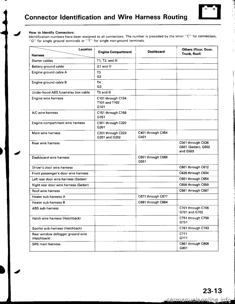
JHow to ldenti{v Connectors:
ldentification numbers have been assigned to all connectors. The number is preceded by the letter "C" for connectors,"G" for single ground terminals ot "f" lor single non-ground terminals.
/
Location
HarnossEngine CompartmentDashboardOthers (Floor, Door,
Trunk. Rooll
Starter cablesT1, T2, and @
Battery ground cableG1 and O
Engine ground cable A
G2
Engine ground cable BT4
G3
Under-hood ABS fuse/relav box cableT5 and @
Engine wire harnessC101 through C134
T101 and T102
G101
A,/C wire harnessC151 through C156
G151
Engine compartment wire harnessC301 through C320
G301
Main wire harnessC201 through C223
G20'l and G202
C40l through C454
G401
Rear wire harnessC501 through C536
G501 (Sedan), G502
and G503
Dashboard wire harnessC551 through C569
G551
Driver's door wire harnessC601 through C612
Front passenger's door wire harnessC626 through C634
Left rear door wire harness (Sedan)C65l through C654
Right rear door wire harness (SedanlC656 throughc659
Roof wire harnessC661 through C667
Heater sub-harness AC671 through C677
Heater sub-harness BC68l through C684
ABS sub-harnessC701 through C706
G701 and G702
Hatch wire harness (Hatchback)C751 through C758
Spoiler sub-harness {Hatchback)C761 through C763
Rear window defogger ground wire
(Hatchback)
c11 l
G77'l
SRS main harnessC801 through C808
G801
23-13
Page 1083 of 1681
Connector ldentification and Wire Harness Routing
Main Wire Hsfness {Left branch}
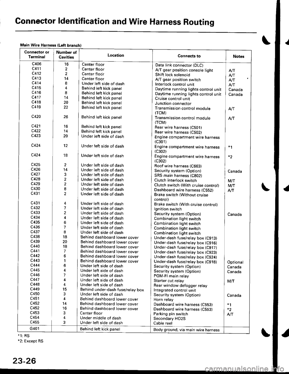
Connector ol
TerminalNumber ol
CavitiesLocationConneqts toNot6s
c406
c41 1
c4't2
c413
c414
c415
c416
c417
c4l8
c419
c420
c421
c422
c423
c424
c424
c425
c426
c427
c428
c429
c430
c431
c43'rc432
c433
c434
c435
c436
c431
c438
c439c440
c441
c442
c443
c444
c445
c446
c447
c44ac449
c450
c451
c452
c452
c453
c454c455
16
2
2
14
4
8
14
20
22
26
Center floor
Center floorCenter flodrCenter floorUnder left side of dashBehind Ieft kick panel
Behind left kick panel
Behind left kick panel
Behind left kick panel
Behind left kick panel
Behind left kick panel
Behind left kick panel
Behind left kick panel
Under left side of dash
Under left side of dash
Under left side of dash
Under left side of dashUnder left side of dashUnder left side of dashUnder left side of dashUnder left side of dashUnder left side of dashUnder left side of dash
Under left side of dashUnder left side of dashUnder left side of dashUnder left side of dashUnder left side of dashUnder left side of dashUnder left side of dashBehind dashboard lower coverBehind dashboard lower coverBehind dashboard lower coverBehind dashboard lower coverBehind dashboard lower coverBehind dashboard lower coverUnder leit side of dashUnder left side of dashUnder left side of dashUnder left side of dashUnder left side of dashBehind under-dash fuse/relay boxUnder left side of dashBehind dashboard lower coverBehind dashboard lower coverBehind dashboard lower coverCenter floorUnder middle of dashUnder left side of dash
Data Iink connector (DLC)
A,/T gear position console lightShift lock solenoidAy'T gear position switchInterlock control unitDaytime running lights controlOaytime running lights controlCruise control unitJunction connectorTransmission control module(rcM)
Transmission control module
{TCM)Rear wire harness (C501)
Rear wire harness (C502)
Engine compartment wire harness(c301)
Engine companment wire harness I *1
(c3021 IEngine compartment wire harness(c302) lRoof wire harness {C663} |Security system {Option) | CanaAaSRS main harness (C802) |Clutch interlock switch I VnClutch switch (With cruise control) M/TDashboard wire harness (C552) AlTBrake switch lwithout cruise Icontrol) |Brake switch (With cruise control)lgnition switch ISecurity system {Option) CanadaCombination light switch /Combination light switch ICombination light switchCombination light switchUnder-dash fuse/relay box (C913)
Under-dash fuse/relay box (C916)
Underdash fuse/relay box (C917)
Under-dash fuse/relay box (C923)
Under-dash fuse/relay box (C924) |Under-dash fuse/relay box {C918) I OptionalSecurity system (Option) CanadaSecurity system (Optionl CanadaPGM-Fl main relayStarter cut relay ] M,.fRear window defogger relay IIntegrated control unitSecurity system (Option) CanadaHorn relay
Dashboard wire harness (C553)
Dashboard wire harness {C553) | -2
Parking pin switch I A,"ISecondary HO2S
Cable reel
Afi
I Atr
lf[
unit ] Canadaunit I Canada
16
14
20
't2
ti
I'
li
ll
li
+4
3
G401 Behind teft kick panelBody ground, via main wire harness*1: RS+2: Except RS
23-26
Page 1097 of 1681
Gonnector ldentification and Wire Harness Routing
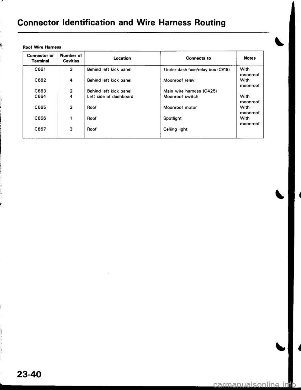
Root Wire Hamoss
Connector or
To.minal
Number ol
Caviti€sLocationConnocts toNotes
c661
c662
c663
c664
c665
LOOO
c667
J
4
a
I
Behind left kick panel
Behind left kick panel
Behind left kick panel
Left side of dashboard
Roof
Roof
Roof
Under-dash fuse/relay box (C919)
Moonroof relay
lvlain wire harness (C425)
Moonroof switch
Moonroof motor
Spotlight
Ceiling light
With
moonroof
With
moontoof
With
moonroof
with
moonroof
With
moonroof
23-40
Page 1106 of 1681
T
I
1
J)
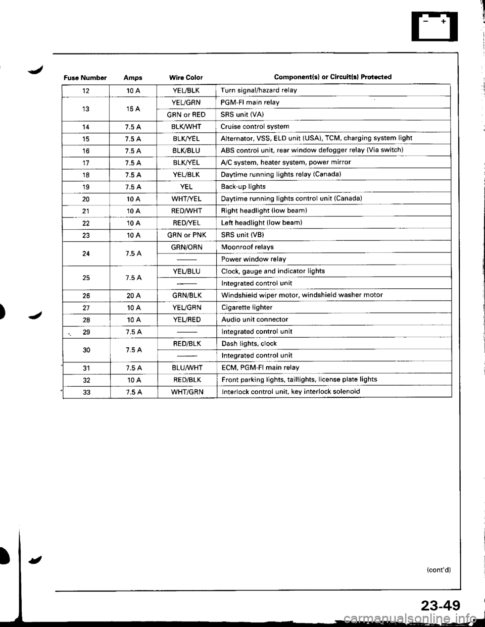
Fuso NumberWire ColorComponent{s} or Circuit(rl ftqt6cted
't210AYEUBLKTurn signal/hazard relay
15 AYEUGRNPGM-Fl main relay
GRN or REDSRS unit (VA)
147.5 ABLK/WHTCruise control system
15BLK/YE LAlternator, VSS, ELD unit (USA), TCM, charging system light
't67.5 ABLVBLUABS control unit, rear window defogger relay (Via switch)
117.5 ABLK//ELAVC system, heater system, power marror
187.5 AYEUBLKDaytime running lights relay (Canada)
197.5 AYELEack-up lights
2010 AWHT/YELDaytime running lights control unit (Canada)
2110 ARED/WHTRight headlight (low beam)
2210 ARE D|YE LLett headlight (low beam)
2310 AGRN or PNKSRS unit (VB)
247.5 AGRN/ORNMoonroof relays
Power window relay
7.5 AYEUBLUClock, gauge and indicator lights
Integrated control unit
2620AGRN/BLKWindshield wiper motor, windshield washer motor
10AYEUGRNCigarette lighter
2810AYEUREDAudio unit connector
29Integrated control unit
30RED/BLKDash lights, clock
Integrated control unit
317.5 A8LU/WHTECM. PGM-Fl main relav
10ARE D/BLKFront parking lights, taillights, license plate lights
7.5 AWHT/GRNInterlock control unit, key interlock solenoid
23-49
Page 1110 of 1681
J
)1 -
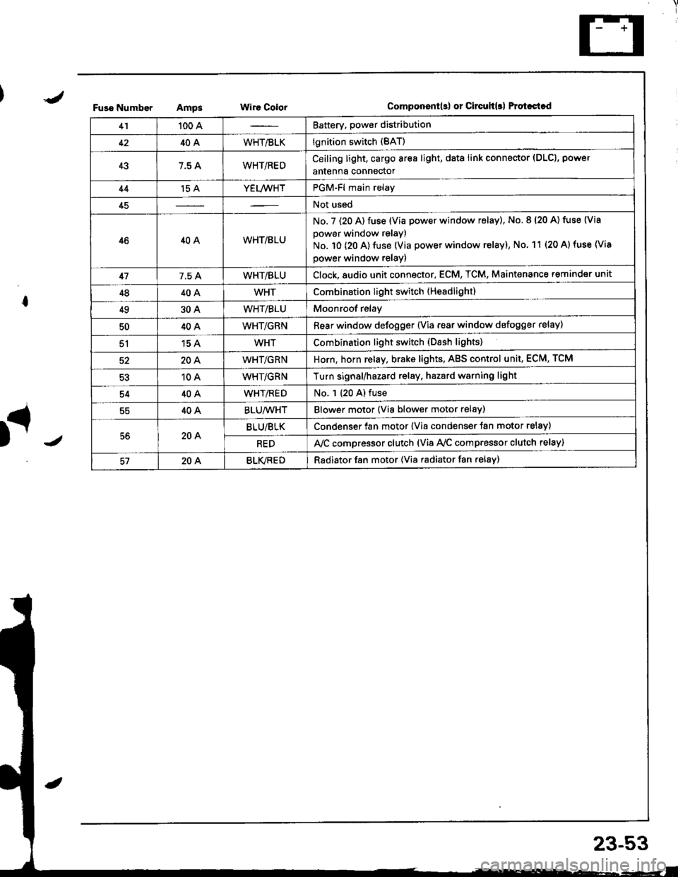
Fuso NumborAmpsWir€ ColorComponent(s) or Circuh(rl Protastcd
41100 ABattery. power distribution
4240AWHT/BLKlgnition switch (BAT)
437.5 AWHT/REDCeiling light, cargo area light, data link connector (DLCl, power
antenna connector
44't5 AYEL/WHTPGM-Fl main relay
45Not used
4640AWHT/8LU
No. 7 (20 A) fuse (Via power window relay), No. 8 (20 A) tuse (Via
power window relay)
No. 10 (20 A) fuse (Via power window relay), No. 11 (20 A) fuse (Via
power window relay)
417.5 AWHT/BLUClock,8udio unit connector, ECM, TCM, Maint€nance reminder unit
4840AWHTCombination light switch (Headlight)
4930AWHT/BLUMoonroof relay
5040AWHT/GRNRear window defogger {Via rear window defogger relay)
51154WHTCombination light switch (Dash lights)
20AWHT/GRNHorn, horn relay, brake lights, AgS control unit, ECM, TCM
10AWHT/GRNTurn signal/hazard relay, hazard warning light
5440AWHT/flEDNo. 1 (20 A) fuse
40ABLU/WHTBlower motor (Via blower motor relsy)
56204BLU/BLKCondenser fan motor (Via condenser {an motor relay)
REDA,/C compressor clutch (via Ay'c comp.essor clutch relay)
57204BLVREDRadiator f8n motor (Via radiator fan relay)
23-53
Page 1240 of 1681
)
I
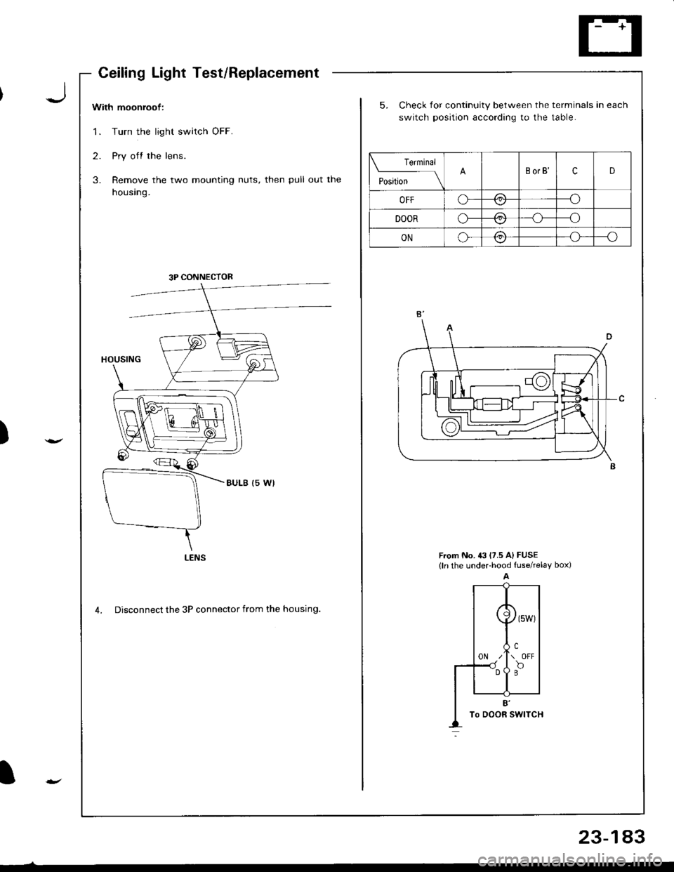
With moonroof:
1. Turn the light switch OFF.
2. Pry off the lens.
3. Remove the two mounting nuts, then pull out the
housing.
5. Check for continuity between the terminals in each
switch position according to the table.
From No. 43 l?.5 A) FUSE(ln the undeFhood fuserelay box)
4. Disconnect the 3P connector from the housing.
Teminal
t"",t*
-l\BorB'cD
OFFo---o\-/
DOORo-/:\--o\:./
ONo-/:\--o\:,/
3P CONNECTOR
LENS
CeilingLightTest/Replacement
23-183
Page 1241 of 1681
Ceiling/Trunk/Cargo Area Lights, Spotlights
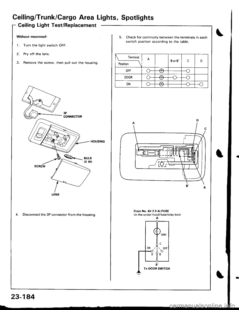
Ceiling Light Test/Replacement
Without moonroof :
1. Turn the light switch OFF.
2. Pry ofl the lens.
3. Remove the screw, then pull out the housing.
HOUSING
4. Disconnect the 3P connector from the housino.
CONNECTOR
23-1a4
5. Check for continuity between the terminals in each
switch position according to the table.
rermrnal
PositionBorB'cD
OFFo-/1--o
DOORo-/A--o
ONo-/a\--o\:,,/--{.J-
From No, i(} {7.5 A} FUSE(ln the under-hood fuse/relay box)A
({
0N z'
Dl
\>l
( owt
!.\. OFF
f,o
B'To DOOR I
Page 1276 of 1681
![HONDA INTEGRA 1998 4.G Owners Manual Moonroof
Component LocatiInde
.J
)
I
onx
J wire colors: GRN/BLK, ]IWHT, GRN and BLK ITest, page 23-68
23-219 HONDA INTEGRA 1998 4.G Owners Manual Moonroof
Component LocatiInde
.J
)
I
onx
J wire colors: GRN/BLK, ]IWHT, GRN and BLK ITest, page 23-68
23-219](/img/13/6069/w960_6069-1275.png)
Moonroof
Component LocatiInde
.J
)
I
onx
J wire colors: GRN/BLK, ]IWHT, GRN and BLK ITest, page 23-68
23-219
Page 1277 of 1681
![HONDA INTEGRA 1998 4.G Owners Manual Moonroof
Circuit Diagram
\,
UNDER,HOOD FUSEi RELAY 8OX
No 41 (100A) N0.42 (40A)
IGNIT ON SW]TCH
M
MOONROOF M0TOR (Harchback)
BLK
G201G401
MOONROOF M0TOR (Sedan)
23-220 HONDA INTEGRA 1998 4.G Owners Manual Moonroof
Circuit Diagram
\,
UNDER,HOOD FUSEi RELAY 8OX
No 41 (100A) N0.42 (40A)
IGNIT ON SW]TCH
M
MOONROOF M0TOR (Harchback)
BLK
G201G401
MOONROOF M0TOR (Sedan)
23-220](/img/13/6069/w960_6069-1276.png)
Moonroof
Circuit Diagram
\,
UNDER,HOOD FUSEi RELAY 8OX
No 41 (100A) N0.42 (40A)
IGNIT ON SW]TCH
M
MOONROOF M0TOR (Harchback)
BLK
G201G401
MOONROOF M0TOR (Sedan)
23-220
Page 1278 of 1681
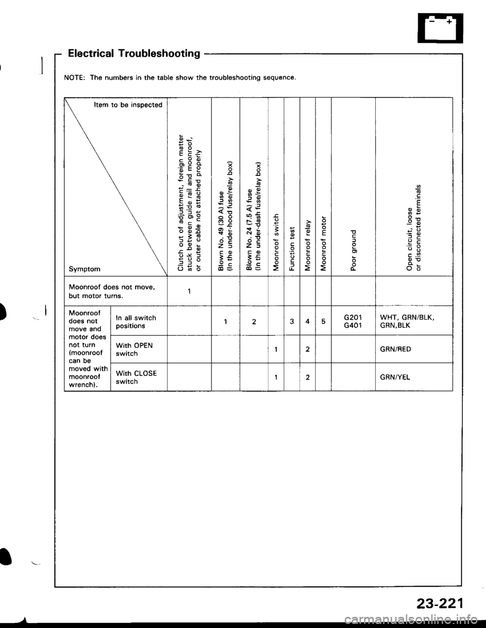
NOTE: The numbers in the table show the troubleshooting sequence.
Item to be insDected
Symptom
cPEox:a'6cY
bp o
qi:6
qE:
b=6'9
* d-9
*i9
?3;
o6b
H6
s
6\.:3
xi
t?c
3€oc
B
F
1
-9oE
!
E
3g
c.9
o6
Moonroof does not move,
but motor turns.1
Moonroot
does not
move anomotor doesnot turn
{moonroofcan be
moved with
moonroot
wrenchl.
ln all switchpositionsEG401
WHT, GRN/BLK,
GRN,BLK
With OPEN
swttcnGRN/RED
With CLOSE
swttcnGRN/YEL
Electrical Troubleshooting
23-221
I