light HONDA INTEGRA 1998 4.G Workshop Manual
[x] Cancel search | Manufacturer: HONDA, Model Year: 1998, Model line: INTEGRA, Model: HONDA INTEGRA 1998 4.GPages: 1681, PDF Size: 54.22 MB
Page 1532 of 1681
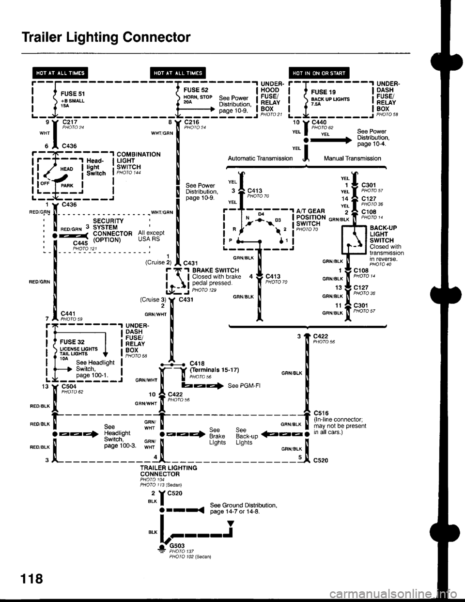
Trailer Lighting Connector
rl;:'
H***
', J "' o, "'oto'o
; -
l-
- - - - - -
iiiJnlw
,i%*,*:l Y* | L-i+--.r tdl##i*
I (c,uise ir I 6a31- ..._ -....__::"
*-
| ."u ", * [ in reverse.
u iti!ms..:y'I'9|| .["...
- -l*s;.,g,."'""
,",0:;"* *";,1 I "*'"tt-fiF'1%"
FUSE32 | i:gPfu [ '89"'::.,"
ili'*'U"T*.,t,., !Fst., J--. .0,.
l[r!g:_l """*",f-l g:lTinars 1s-17)
;04 [ ba{ See PGM-FI)ro 62 fi A cczz
".":.:Xt*" """,,J"',it'*'**=
.EE4 :e?d,,!h,
""' i-:.+ 9t= 9:9___- €::5 ;;;irc;;ai
".o".* | il',iii'1t.. $11 |
Lisnii Lb;i;' o"n,.* |
. JL-----------1JI- ljl c'ro
TRAILER LIGHTINGCONNECTOR
2 Y Cs20BLX I - See Ground Drstnbutron,Orrr{ Oaqe r4-7 or 14-6.T-IY"," I I--'I^-rrr-
r:-910,3,.,,
PHOIO 102 lsedanl
5 A C435 | ver- | IrcsE rv-q
if:T---r J;l l-'!ti^*t" I oromaticrransmission I Manuarrransmission
ll(':'iis,i'"nl;*ri"* i ffi
i l#.1"-"
I sw*ch ' Piu''J 'r
L*'**r*,
"]l
"*. "iU t*.,
L'_-_L-_-_'___..!
".o 0,," l( "o.u I
o"o" to-s
_:l_____ 1,!,| ,";:,'","
"'""i'!;
:isr"H"" ^; j""":"" t []t lil?lfililr
""""ff*:;
Lfl6ti*-" i--g-----J
F T'I BRAKE SWITCH TI
Ilj iiifl'#'!"';l-"' tr
""#"3 "
lf c431 GRN/BIK
I
it
*)ir;***"{:"- [:**"
"":r[;;,,
-",*l"Y ""#B'' J.l1nqi, se€Power
.-3:i!i,Jil
I swllch I PH(,,/ci r44
! ,"" ,o*", "ttl "T
U .rot
8 Y C216
il-l-
118
Page 1548 of 1681
- How the Circuit Works
The immobilizer system is designed to prevent the
car f rom being started without the owner's ignition
key. lf an attempt is made to start the car without
the correct key, the immobilizer system will disable
the car's fuel supply.
The immobilizer system consists of the ignition key,
immobilizer receiver unit, immobilizer indicator
light, PGM-FI main relay, fuel pump, and the PCM
or ECM.
With the ignition switch in ON (ll) or START (lll), the
immobilizer receiver unit and the PCM or ECM
receive an "ignition on" signal through fuse 44 and
the PGM-FI main relay. The PCM or ECM then
sends power to the ignition key transponder through
the immobilizer receiver unit. The transponder then
sends a coded signal back to the PCM or ECM
through the receiver unit. lf the signal is correct, the
PCM or ECM will energize the car's fuel supply
system by grounding the PGM-FI main relay. The
immobilizer indicator light flashes a code to indicate
that the correct key has been inserted. lf the
ignition key signal is not correct, the PCM or ECM
will not energize the car's fuel supply system by not
grounding the PGM-Fl main relay. The immobilizer
indicator light then flashes a code to indicate that an
incorrect key has been inserted.
Refer to the Service Manual (Section 23,
Body Electrical) for specific tests and
troubleshooting procedures.
132-1
Page 1550 of 1681

a
)'-
I
1
i
I
-----'!rex^ER illt#lP$3"'s'J39"
I li33,i i i H^- lPHarc2'
l_.,*_______,fr_j F;t':"' i*.,;-,; lnpu Inpw t iidr'o az 9 l, C2j6' Ptioro )4,.llF-------il(coo+ r
I I
wHr I see tuwer
a.rn;o
I
eL,"v*r
I ii---- 3;*1tB:
.-r--------J^.^. I -l'.
f
------l6-f "',f""3,,
u.^,".o I ".*-", i
TI
,o l--------J "o,,
er-rcneol arx,wxrl I f-------.Jln:SY,,
'o
f
----- -qh9i","
""
i
aix,wxr
!
LIGHTFLASHER
+ (cont'd)
J
;LT-ffi}-hf[
-";][-. -:-[;^.
rz A-_-"1 '1" -1A-----------19
tlar.x.n:o ll ELKwHr ll GRN'YE
I tls A__-- -_--9J.t---- - - --- - - -1!
ll ,ll ","',' ll
' ' -
[*"*:iL_____::lL_
ill
""'"n
!-----:1 sEcuRrrr i!
I unrock output Loc* output fiirn[|. ! Eg,f"o. i\. siren contror ,gil,", ! ildib., I| -;;-q Hood swirch input t : r c44iA------ 7
PHOrO 5e9 t|'- - -^:1t- - - - - - - - ;'lf
!1ft"c*39,,, ij:g+ ffi,U',:.
*.ll ".o,o"n I
pase'ro*l'
]ZJ{ T
-
-:[:-;nT:===;.TIf
-----
ithT#'**l!$gs]'
: ;s__+_______+';,;.... i ! i,,#;'*' iF.ifl,
i I T1"'
""".lnro.
i Ljry-i3,'],o,,0 ',,u"if, F"l%oo ' L-*'-----
, sEcuRrrY rtl nooo ; "to".^f,
fl tts,'Jt;; l/.1:#[%
I cdHead'isht
u .* i IgJ'e*.,
";
"'r"J
"ro
' neoeLxf
Y'ioic"n 'ft*"'l*u.u"o
i t:;:['fig"'
Itr
"*l ilu"#:31 i ".-f
I I i iatr'f'ni"xl
I -i o,o' i **1
133-1
Page 1554 of 1681
- How the Circuit Works
The security system control unit has a 3 position
switch: Manual. Auto. and Auto Lock. Here's what
happens when you arm the system, regardless ol
the switch position:
o The parking lights will flash once.
. The security indicator will flash once per second
after the system is armed.
With the switch in the Manual position, the security
system can only be armed by using the remote
control transmitter, After you remove the key from
the ignition and close all doors, the hood (if
equipped with the optional hood switch), the hatch
or trunk. Dress the lock button on the transmitter
and the system will arm (if the system is in the beep
sound mode, the horn will sound once). The doors
will automatically lock when the system is armed.
With the switch in the Auto position, the security
system will arm itself within about 20 seconds after
you turn the engine off, remove the key from the
ignition, and close the halch or trunk, the hood (if
equipped with the optional hood switch), or last
door. lf a door is opened during the 2o-second exit
delay time, the timer will reset itself . The remote
control transmitler can still be used to arm the
system with the switch in Auto position (see manual
for details).
With the switch in Auto Lock position, the security
system will arm itself and lock the doors about 20
seconds after you turn the engine of{, remove the
key from the ignition, and close the hatch or trunk,
the hood (if equipped with the optional hood
switch), or last door. lf a door is opened during the
2o-second exit delay time, the timer will reset. The
remote control transmitter can still be used to arm
the system in the Auto Lock position.
Triggering the Alarm
After the security system is armed, the sound ot
breaking glass or the opening of a door, hood,
hatch or trunk will trigger the alarm, and cause
the following:
r The horn will sound for30 seconds.
The optional siren will sound lor 60 seconds.
. The parking lights will flash.
. The security indicator LED will flash twice per
second.
. The starter will be disabled.
At the end of the alarm cycle, the system will
automatically rearm.
Disarming the Security System
There are two ways to disarm the security system:
. With the transmitter
o With the disarm/valet switch
When the system is disarmed, regardless of the
method used, the parking lights will flash two times if
the alarm has not been triggered and three times if
the alarm has been triggered. To disarm the system
with the transmitter, press the unlock button (if the
system is in the beep sound mode, the horn will
sound two times if the alarm has not been triggered,
however, will sound three times if the alarm has
been triggered). The driver's door will unlock
(pressing the unlock button twice will unlock all
doors).
To disarm the security system using the
disarm/valet switch, enter the car and turn the
ignition switch to ON (ll) then press the disarm/valet
switch button. lf you open the door when the control
unit switch is in Auto or Auto Lock, a 2o-second
entry delay will give you time to disarm the system.
However, when the system is armed by the
transmitter, the entry delay time is changed to zero
seconds, and the alarm is triggered as soon as you
oDen the door.
ldentifying Tripped Sensors
The system will indicate the sensor which triggered
the alarm through the security indicator LED. While
sitting inside the vehicle wlth the key out of the
ignition switch, all doors, the hood (if equipped with
the optional hood swilch), the hatch or trunk must be
closed. Press and hold the disarm/valet switch.
Press the lock button and then the unlock button of
the transmitter. Belease the disarm/valet switch. The
status LED will blink according to the following code:
Sensors
Door
Trunk/Hatch
System Switches
Glass Breakage
Hood (Optional)
Number ol Flashes
1 blink, pause, repeat
2 blinks, pause, repeat
3 blinks, pause, repeat
4 blinks, pause, repeat
5 blinks, pause, repeat
For further operating instructions and troubleshooting,
see the security system owner's manual.
133-5
Page 1565 of 1681
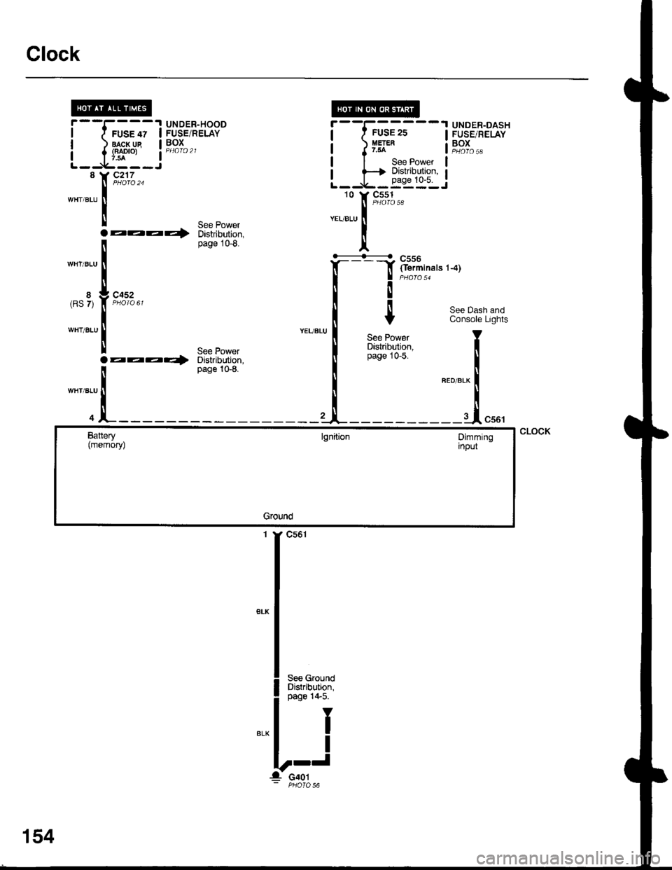
Clock
I
I
8(RS 7)
WHT/BLU
UNDER-HOODruse lz I FUSE/RELAY
lragr-lle I Pg^I^ ^
{f*'o, a PHafo 21
c2'17
aaaQ
c452
aaaa)'
"-,,[r*"
nnT,i"".'-.)
I
Y
See PowarDistribution,page 10-5.
r--I------1 UNDER-DASHI f FUSE2S I FUSE,RELAY
a J y5t* a"';L,,
| | See Power l
r f+ ?:"i:q*t:"' IL--9,-.-=:-:J10 Y C551
8
WHT/BLU
WHT/BLU
See PowerDistribution,page 10-8.
WHT/BLU
See PowerDistribution,page 10-8.
See Dash andConsole Lights
T
I
"ao,"a* f
--J"*'
CLOCKBattery(memoryJlgnitionDimminginput
Ground
1 Y C561
',54
Page 1566 of 1681
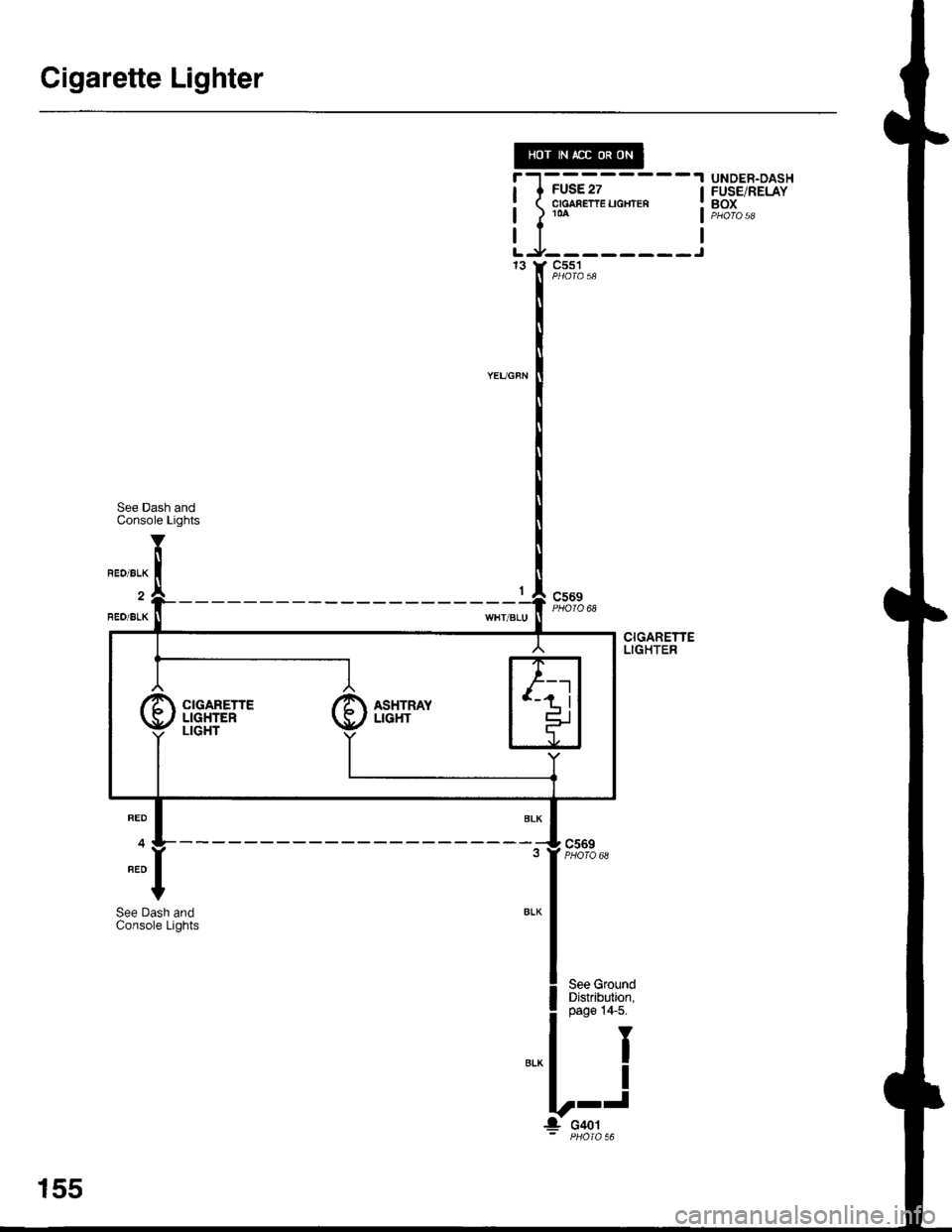
Cigarette Lighter
iltt-"--- _-j" r F,*%*
UNDER.DASHFUSE/RELAYBOX
See Dash andConsole Lights
BED/BLK
FEO/BLK
c569PHOIQ 68
c569PHOTO 68
CIGARETTELIGHTER
RED
4
BED
See Dash andConsole Lights
I
I
J
CIGARETTE /E ASHTRAY
155
J o+ot
Page 1598 of 1681
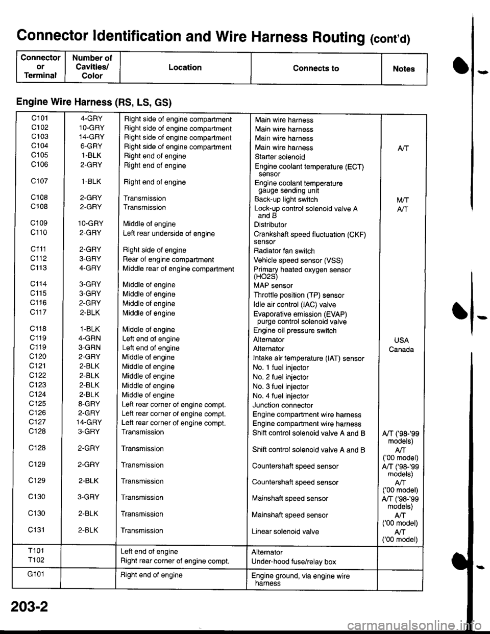
Connector ldentification and Wire Harness Routing (cont,d)
Connector
or
Terminal
Number ot
Cavities/
Color
LocationConnects toNotes
Engine Wire Harness (RS, LS, GS)
c101
c102
c103
c104
c105
c106
c 107
c108
c108
c'1 09
c110
c111
cl12
c113
c'114
c115
c116
c117
c118
c119
c1 19
c120
c121
c122
c123
c124
cl25
cl26
c127
Ql28
c128
c129
c 129
c130
c'l30
c131
4.GRY
1O.GRY
14-GRY
6-GRY
1.BLK
2-GRY
,1-BLK
2-GRY
2.GRY
1O-GRY
2-GRY
2-GRY
3-GRY
4-GRY
3-GRY
3-GRY
2-GRY
2.BLK
.1-BLK
4-GRN
3-GRN
2-GRY
2.BLK
2-BLK
2-BLK
2.BLK
8-GRY
2-GRY
14-GRY
3-GRY
2.GRY
2.GRY
2-BLK
3-GRY
2-BLK
2-BLK
Right side of engine compartment
Right side of engine compartment
Right side ot engine compartment
Right side of engine compartment
Right end of engine
Right end of engine
Right end of engine
Transmission
Transmission
lvliddle ol engine
Lett rear underside of engine
Right side ol engine
Rear of engine compartment
Middle rear ol engine compartment
Middle ol engine
Middle of engine
Middle ol engine
l\4iddle of engine
Middle of engine
Left end ot engine
Lett end of engine
Middle of engine
N,liddle ol engine
Middle of engine
Middle of engine
Middle of engine
Left rear corner of engine compt.
Lelt rear corner of engine compt.
Left rear corner of engine compt.
Transmission
Transmission
Transmission
Transmission
Transmission
Transmission
Transmission
Main wire harness
Main wire harness
Main wire harness
Main wire harness
Starter solenoid
Engine coolant temperature (ECT)sensor
Engine coolant temperaturegauge sending unit
Back-up light switch
Lock-up control solenoid valve Aand B
Distributor
Crankshaft speed fluctuation (CKF)sensor
Radiator fan switch
Vehicle speed sensor (VSS)
Primary heated oxvoen sensor(H02s)
MAP sensor
Throttle position (TP) sensor
ldle air control (lAC) valve
Evaporative emission (EVAP)purge control solenoid valve
Engine oil pressure switch
Alternator
Alternator
Intake air temperature (lAT) sensor
No. I fuel injector
No. 2 fuel injector
No. 3 tuel injector
No. 4 fuel injector
Junction connector
Engine compartment wire harness
Engine compartment wire harness
Shitt control solenoid valve A and B
Shift control solenoid valve A and B
Countershaft speed sensor
Countershatt speed sensor
lvtainshatt speed sensor
Mainshaft speed sensor
Linear solenoid valve
NT
[/VT
A"/T
USA
Canada
A/T (98199models)
AIT('00 model)
A,/T ('98-'�99models)
('00 model)
A,/T f98-'99models)
Atf('00 model)
AN('00 model)
T101
T102
Left end of engine
Right rear corner of engine compt.
Alternator
Under-hood fuse/relay box
G'101Right end ot engineEngine ground, via engine wirenarness
o
I
203-2
Page 1600 of 1681
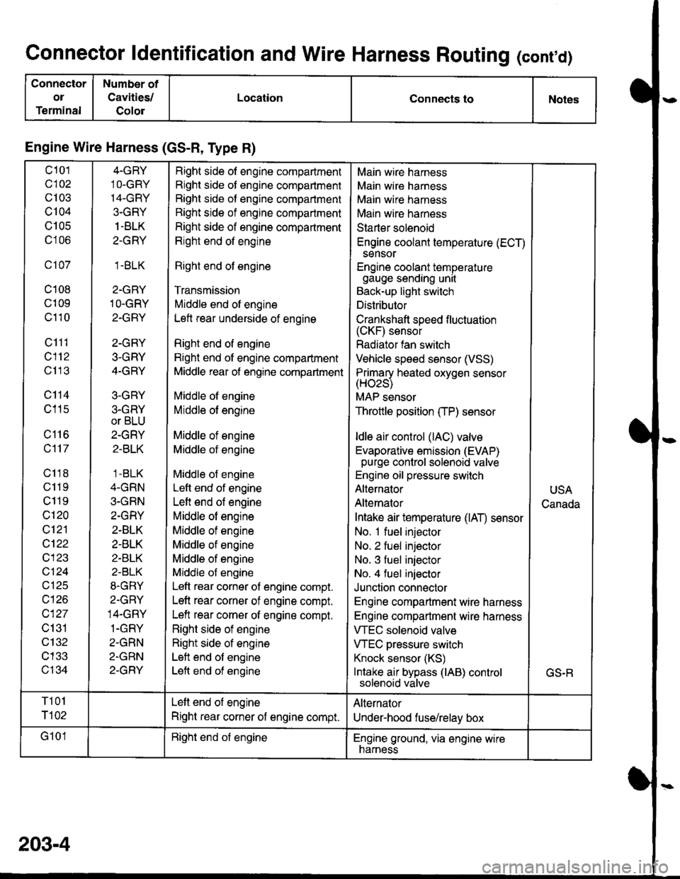
Connector ldentification and Wire Harness Routing (conrd)
Connector
ol
Terminal
Number of
Cavities/
Golor
LocationConnects toNotes
Engine Wire Harness (GS-R, Type R)
c101
c102
c103
c104
U IUC
c106
c107
c108
c109
c110
c111
c112
c113
c114
c115
c116
c117
c118
c11 9
c119
c120
c121
cl22
c123
vtzl
wt10
c127
c131
c132
c133
c134
4-GRY
1O-GRY'I4-GRY
3-GRY
1 -BLK
2-GRY
1.BLK
2-GRY
1O-GRY
2-GRY
2-GRY
3-GRY
4-GRY
3-GRY
3.GRY
or BLU
2-GRY
2-BLK
1 -BLK
4-GRN
3-GRN
2.GRY
2-BLK
2-BLK
2-BLK
2-BLK
8-GRY
2.GRY
14-GRY
1-GRY
2-GRN
2-GRN
2-GRY
Right side of engine compartment
Right side of engine compartment
Bight side of engine compartment
Right side of engine compartment
Right side of engine compartment
Right end of engine
Right end of engine
Transmission
Middle end of engine
Left rear underside of engine
Right end of engine
Right end of engine compartment
Middle rear of engine compartment
Middle of engine
Middle of engine
Middle of engine
Middle of engine
Middle of engine
Left end of engine
Left end of engine
Middle of engine
Middle of engine
Middle of engine
Middle of engine
Middle of engine
Left rear corner of engine compt.
Left rear corner of engine compt.
Left rear corner of engine compt.
Right side of engine
Right side of engine
Left end of engine
Left end of engine
Main wire harness
Main wire harness
Main wire harness
Main wire harness
Starter solenoid
Engine coolant temperature (ECT)
sensor
Engine coolant temperaturegauge sending unit
Back-up light switch
Distributor
Crankshaft speed f luctuation(CKF) sensor
Radiator fan switch
Vehicle speed sensor (VSS)
Primarv heated oxvoen sensor(Hozs)
MAP sensor
Throttle position (TP) sensor
ldle air control (lAC) valve
Evaporative emission (EVAP)purge control solenoid valve
Engine oil pressure switch
Alternator
Alternator
Intake air temperature (lAT) sensor
No. 1 fuel injector
No. 2 fuel injector
No. 3 fuel injector
No. 4 fuel injector
Junction connector
Engine compartment wire harness
Engine compartment wire harness
VTEC solenoid valve
VTEC pressure switch
Knock sensor (KS)
Intake air bypass (lAB) controlsolenoid valve
USA
Canada
GS.R
T101
r102
Left end of engine
Right rear corner of engine compt.
Alternator
Under-hood fuse/relay box
G101Right end of engineEngine ground, via engine wirenarness
203-4
Page 1602 of 1681
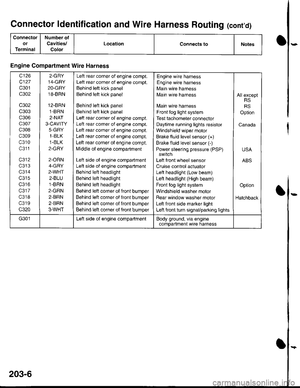
Connector ldentification and Wire Harness Routing (cont'd)
Connector
or
Terminal
Number of
Cavities/
Color
LocationConnects toNotes
Engine Compartment Wire Harness
wt10
c127
c301
c302
c302
c303
c306
c307
c308
c309
c310
c311
T/JIJ
c314
c315
IJJ IO
c317
c318
c319
c320
2.GRY
14-GBY
2O-GRY
18-BRN
12-BRN
1-BRN
2.NAT
3.CAVITY
J-(l|-I Y
1-BLK
1-BLK
Z-IfFI T
2-ORN
4-GRY
2-WHT
2-BLU
1-BRN
2-GRN
2-BRN
2-BRN
3-WHT
Left rear corner of engine compt.
Left rear corner of engine compt.
Behind left kick panel
Behind left kick panel
Behind left kick panel
Behind left kick panel
Left rear corner of engine compt.
Left rear corner of engine compt.
Left rear corner of engine compt.
Left rear corner of engine compt.
Left rear corner of engine compt.
Middle of engine compartment
Left side of engine compartment
Lett side of engine compartment
Behind left headlight
Behind left headlight
Behind left headlight
Behind left corner of front bumper
Behind left corner of front bumper
Behind left corner of fronl bumper
Behind left corner of {ront bumper
Engine wire harness
Engine wire harness
Main wire harness
Main wire harness
Main wire harness
Front log light system
Test tachometer connector
Daytime running lights resistor
Windshield wlper motor
Brake fluid level sensor (+)
Brake fluid level sensor (-)
Power steering pressure (PSP)
switch
Left front wheel sensor
Cruise control actuator
Left headlight (Low beam)
Left headlight (High beam)
Front fog light system
Windshield washer motor
Rear window washer molor
Left front side marker light
Left front turn signal/parking lights
All except
RS
RS
Option
Canada
USA
ABS
Option
Hatchback
G301Left side of engine compartmentBody ground, via engine
comDartment wire harness
203-6
Page 1604 of 1681
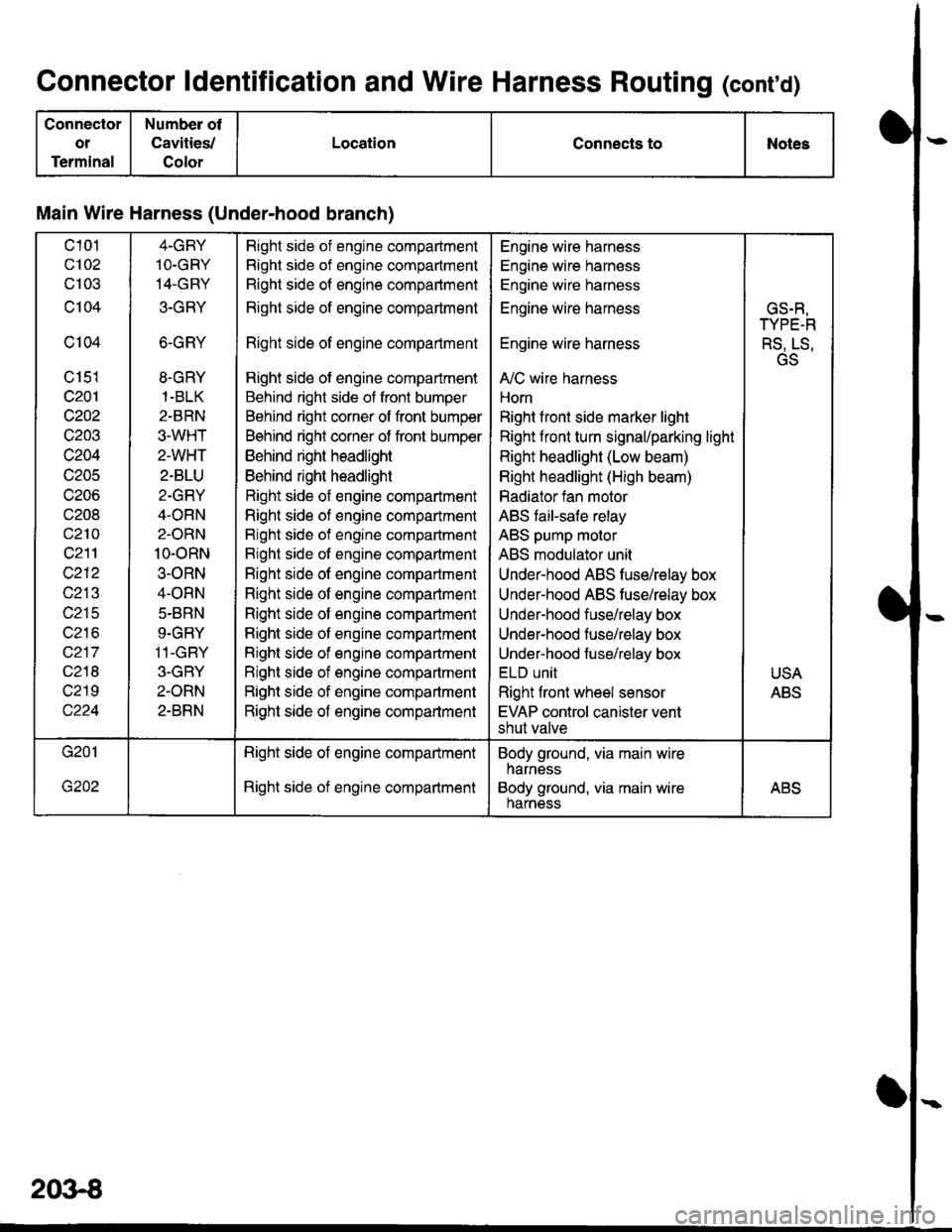
Connector ldentification and Wire Harness Routing (conrd)
Connector
ot
Terminal
Number of
Cavities,/
Color
LocationConnects toNotes
Main Wire Harness (Under-hood branch)
c101
c102
cl03
c104
c104
c151
c201
c202
c203
c204
c205
c206
c208
c210
c211
c212
c213
c215
wz to
c217
c218
c219
4-GBY
1O.GRY
14.GRY
3-GRY
6-GRY
8.GRY
1-BLK
2-BRN
3.WHT
2-WHT
2-BLU
2-GRY
4-ORN
2-ORN
10-oRN
3-ORN
4-ORN
5.BRN
9.GRY
11-GBY
3-GBY
2-ORN
2-BRN
Right side of engine compadment
Right side of engine compartment
Right side of engine compartment
Right side of engine compartment
Right side of engine compartment
Right side of engine compartment
Behind right side of front bumper
Behind right corner of front bumper
Behind right corner of front bumper
Behind right headlight
Behind right headlight
Right side of engine compartment
Righl side of engine compartment
Right side of engine compartment
Bight side of engine compartment
Right side of engine compartment
Right side of engine compartment
Right side of engine compartment
Right side of engine companment
Right side of engine compartment
Right side of engine compartment
Right side of engine compartment
Right side of engine compartment
Engine wire harness
Engine wire harness
Engine wire harness
Engine wire harness
Engine wire harness
A,/C wire harness
Horn
Right f ront side marker light
Right front turn signal/parking light
Right headlight (Low beam)
Right headlight (High beam)
Radiator fan motor
ABS faiFsafe relay
ABS pump molor
ABS modulator unit
Under-hood ABS fuse/relay box
Under-hood ABS tusehelay box
Under-hood fuse/relay box
Under-hood fuse/relay box
Under-hood fuse/relay box
ELU UNII
Right front wheel sensor
EVAP control canister vent
shut valve
GS.R,
TYPE-R
RS, LS,
GS
USA
ABS
Right side of engine compartment
Right side of engine compartment
Body ground, via main wire
harness
Body ground, via main wireharnessABS
2()3€