engine HONDA INTEGRA 1998 4.G Workshop Manual
[x] Cancel search | Manufacturer: HONDA, Model Year: 1998, Model line: INTEGRA, Model: HONDA INTEGRA 1998 4.GPages: 1681, PDF Size: 54.22 MB
Page 1477 of 1681
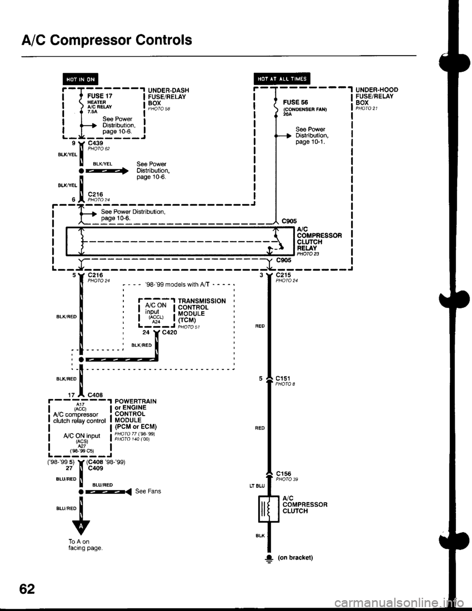
A/C Gompressor Controls
FUS€ 55(GoNDEXSEA fAN)204
UNDER.HOOOFUSE/RELAYBOX
@r-T------.I UNDER-DASHI t FUSE 17 I FUSE/RELAY
| ) LBEL, t19T^..
I I r.uo ^ _ l--*I I lee Power I: {--t Diskibdion. :
L_I_fiT_.!I Y C439
".^,tr. |
"'oto u'
ll erx,.ver 36€ Powera ---i Distribution,page tO-0.
BLX/YEL I
" IFi:,u.^
See PowerDislribution,page 1G'l .
NCCOMPR€SSORCLUTCHREI.AYPtloro n-Y c905
-*----------f
"*l'--
,1,*,
"-l
"ft:,,
lll[ 133,]+'"1F**
;f
I. (on bracket)
- '98199 models with A/T - - - -
r -^ ^-^:'l TRANSMTSSTONCONTROL: rr!P!I.. : MoDULE| ^;;', | (rcM)L-Z-J iuoro sr24 Y C420
BLK/RED
POWERTRAINor ENGINECONTROLMODULE(PCM or ECM)PHOfO 77 (94 99)ly'C ON inDut{ACS}
L--,S"s-i(98- 99 s) Y (C4o8 '�98-'�99)
27 tl C409
",-r,"ao II aLuneo
ar< ree Fans
ilaurneo I
v
ToAonlacrng page.
62
Page 1479 of 1681
A/C Gompressor Controls (conrd)
- How the Circuit Works
Battery voltage is supplied through fuse 56 to the
A,/C compressor clutch relay contacts at all times.
With the ignition switch in ON (ll), voltage is applied
to the coil of the A,/C compressor clutch relay
through fuse 17. When you push the A,/C switch
ON, and the heater fan switch is in posation 1, 2, 3,
or 4, a "ground" input is provided to the engine or
powertrain control module (ECM or PCM) through
the A,/C thermostat and the A,/C pressure switch.
The A,/C compressor clutch relay is grounded by the
engine or powertrain control module (ECM or PCM).
When energized, the A,/C compressor clutch relay
allows battery voltage to turn on the A,/C
comDressor clutch,
The A,/C ON indicator light comes on when the A"/C
system is requested.
A,/C Thermostat
The A,/C thermostat is located on the evaoorator
housing. The AJC thermostat turns off the A,/C
compressor clutch if the temperature at the
evaporator goes below 3'C (37'F). This prevents
condensation from freezing on the evaporator fins
and blocking the air delivery into the passenger
compartment. The blower motor will keep running
when the sensor lurns off the compressor.
A,/C Pressure Switch
The A,/C pressure switch is located in the condenser
outlet line where refrigerant is in a high
temperature/high pressure liquid state. The switch
will sense abnormally high or low pressure, and
open the circuit. This removes ground, and the
compressor will stop running.
Refer to the Service Manual (Section 22,
Air Conditioning) for specific tests or
troubleshooting procedures.
62-2
Page 1480 of 1681
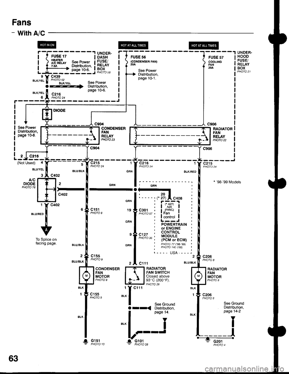
Fans
- with
|------
See PowerDistribution,page 1G6.
;;;----13X3,5"
l,fP"[r s"" eo'""t
A/C -
E@
UNDER.HOODFUSE/RELAYBOXDistribution,
FUSE 56(coxoEr{sE8 faN}FUSE 57COOLING
204
FUSE/RELAY
2
(Not
I
I
I
I
IL
I Y C439sucrel ll PHoro"62rrr.
orl
*T'.I.
:-gg]gi Ji,'oio,,,
Seg PowerDistribution,page 10.6.c216y":':---______i
See PowerDbtribution,page lG1.
c2'16 1
BLKBEO
' POWERTRAIN ,
: or ENGINE, CONTROL ::,::A ,. ' MODULE ;(PCM or ECM) ,' PHOIA 77 (9A 99 |' PHofa 14a $q :!---- usA.----
COI{DENSERFANRELAYPHOTO 23
RADIATORFANRELAYHlofa 22
c215-----J
* '98199 [,4odels
cltl8LU/BLK
c9{t6
c206
c206
ffi-
".",".t"f
"oo' 6
i
v
To Splice onfacing page
c151
c155
BLU/BIK
BLU/ALK
CONDENSERFANMOTOR
RADIATORFANMOTOR
RADIATORFAN SWITCHClosed above93"C (200"F).
".:r
"'''
I see c,ornoarr< Distribution,
".,.f
','"i.
-lr:;--: PHafo 28
c155PHOTA 9
See GroundDistribution,page 14-2
Y
I
63
I. G151
Page 1483 of 1681
Fans (cont'd)
- How the Gircuit Works
When the ignition switch is in ON (ll), voltage is
applied to the coils of the radiator fan relay and the
condenser fan relay (with A,/C) through fuse 17.
Whenever a ground is provided to the radiator fan
relay and condenser fan relay, the relays are
energized, turning on the radiator fan motor and
condenser fan motor. The relays can be grounded
by the radiator fan switch, engine or powertrain
control module (ECM or PCM) (USA), or the A,/C
and heater lan switches via the A'lC pressure switch
and the A,/C lhermostat.
A,/C Thermostat
The A,/C thermostat is located on the evaporator
housing. The A/C thermostat turns oft the A/C
compressor clutch it the temperature at the
evaporator goes below 3'C (37"F). This prevents
condensalion from freezing on the evaporator fins
and blocking the air delivery into the passenger
compartment. lt the temperature goes below 3'C
(37'F) turning off the A"/C thermostat, and the
BLU/RED wire at the A,/C diode was the only wire
providing ground to the condenser and radiator
fan relays (A,/C switch on, heater fans switch on,
radiator fan switch open, and ECM or PCM fan
controi output not grounded), the relay will
deenergize removing voltage from the condenser
and radiator fan motors causing them to stop
running.
A,/C Pressure Switch
The AJC oressure switch is located in the condenser
outlet line where refrigerant is in a high
temperature/high pressure liquid state. The A,/C
switch turns off the A,/C compressor clutch if it
senses abnormally high or low pressure. lf the A'lC
pressure switch opens, and the BLU/RED wire at
the A/C diode was the only wire providing ground
to the condenser and radiator fan relays (L/C switch
on, heater fans switch on, radiator lan switch open'
and ECM or PCM fan control output not grounded),
the relay will deenergize removing voltage from the
condenser and radiator fan motors causing them to
stop running.
A./C Diode
This diode orevents the radiator fan switch f rom
grounding the "A'lC ON" input to the engine or
powertrain control module (ECM or PCM).
Refer to the Service Manual (Section 23, Electrical)
for specific tests or troubleshooting procedures.
63-3
Page 1486 of 1681
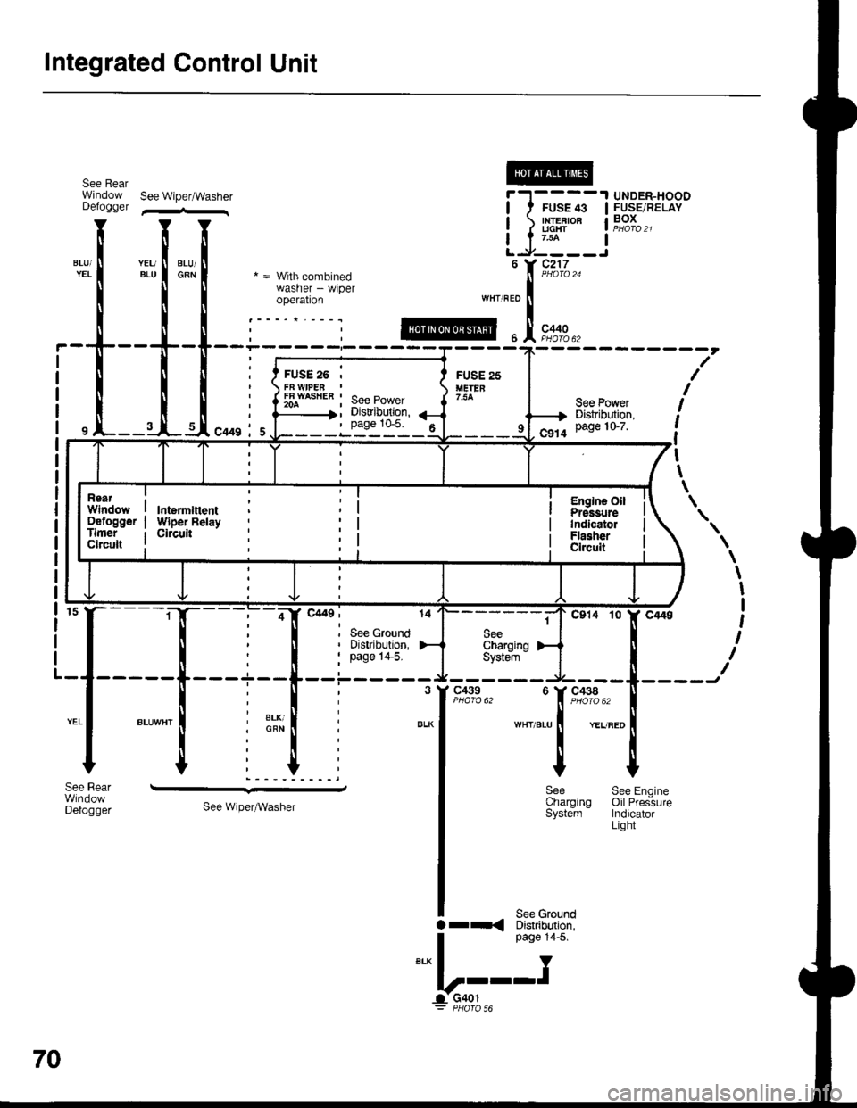
Integrated Control Unit
see Rear @Window See Wipef/Washer |-'l----
, See Ground' Distribution,
: pase 14-5.
c439
\
\
I
I
t
I
I
WHT/BLU
c438
YEUREO
'r9,x3
*t
Y
SeeCharoinoSyste'm '
--.-,
See Wiper^Vasher
See EngineOil PressureIndicatorLight
rr{See GroundDishibution,page 14-5.
Y
v---!G401
Window See Wioef/Washer f -'l-- - -'l UNDER-HOODDefogser ,-- | I rUS: +e IFUSE/RELAY
I I I llg:-i***'
1'11f ;'.il::ll ^-.wlhcombined utr?i;,'",,
I I I :,8:[il; * o"' ,n", ",o I
!!!i.t@..!.,*,*..
i
-T--
T-[-- :-;:=::::::{----1-- - - - - - - - -
7'
illli{ry;a';:i {iii:*l i
i, tr---I".!,.*, i, Ljiri'dt'l-t{-:--h i:tf{#;r {
il
L-
See Rear
Defogger
FUSE 26 ,
FFAWASiIEB ' See power
' page 10-5. 6
RearWindowDefoggerTimerCircult
IntermftentWiper RelayCircult
Englns OilPrgssureIndicatolFlasherClrcuit
70
!..
Page 1490 of 1681
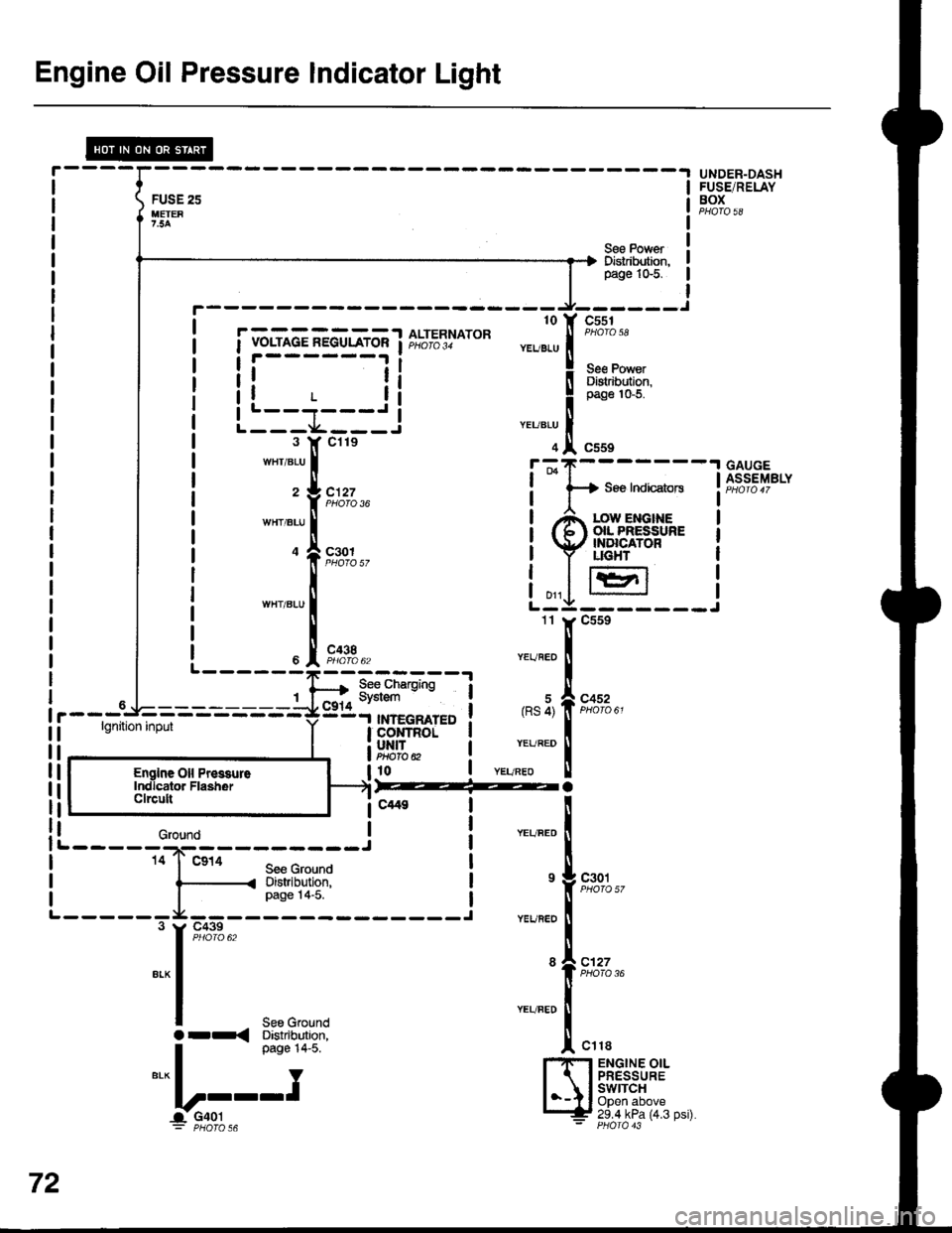
Engine Oil Pressure Indicator Light
lgnition input
L - - - - - *---- ---- --J14 I' Ca14See GroundDistribution,page l4-5.
L------
See Ground
r------- ----__J_--___J
| .---- . to Y cssi
i i vor-mce nEGuLAroR i f,t"t5l|otot ".u"., f
ono'" "
! !i------li il;ffi,r?rl$
i lL--j---.I ! 1*n"'o.u
I L___L___.,i ".,,".u I| 3 lf cile ol csss
I
UNDER-DASHFUSE/RELAYBOX
Ses PovrerDistribution,p,age 1G5.
wHr/BLU | !-;T-------1.;T
c't27 !
-
f+ see IndicatorsPHO|O 36 | I
| ,A low er,rcrxeI { 6l (xL PfiESSURE
s::t.. i Y l.x8i.."i'o'ttr-r
i ,,,1 lr=r,l
L-:g-------
Z J-C.tZz ! H SBe Indicators
GAUGEASSEMBLY
""'.,[r,o_,._
i
eh"#fiFs$.
11
c438
c452
r(RS 4)
YEURED
6
"'"1[,*.,
"rr"ao
I
'-"-[':,':"
l-rlFl ENGTNE OtLI 1 I PRESSURE
l--Il,8yjl?h:^,
Englne Oil Pr6guroIndlcator FlasherClrcull
72
o--< Distrtbution,
Page 1491 of 1681
- How the Circuit Works
The low engine oil pressure indicator light works in
two ways: il flashes continuously following a
momentary loss of engine oil pressure, or it comes
on and stays on with a complete loss of engine oil
oressure,
When the engine first starts, before its oil pressure
rises above 4.3 psi, voltage is applied to the closed
and grounded engine oil pressure switch and the
light comes on to test the bulb.
With the engine running, voltage is applied at the
WHT/BLU wire of the integrated control unit. With
normal engine oil pressure, the engine oil pressure
switch is open and the low oil pressure indicator
light does not come on. lf the engine oil pressure
switch closes momentarily (more than 0.5 seconds)
but then opens again, the YEURED wire at the
integrated control unit will sense ground through the
switch. The integrated control unit will then provide
and remove ground for the low oil pressure indicator
light through the YEURED wire. The light will flash
on and off until you turn the ignition switch off. The
flashing feature will not work until 30 seconds after
initial voltage is applied to the WHT/BLU wire of the
oil pressure indrcator llasher circuit. This delay
keeps the low oil pressure indicator light from
coming on during engine warm-up.
lf engine oil pressure falls below 4.3 psi and does
not increase, the engine oil pressure switch will stay
closed. The low oil pressure indicator light will then
come on and stay on.
Refer to the Service Manual (Section 23, Electrical)
for specific tests or troubleshooting procedures.
72-1
Page 1496 of 1681
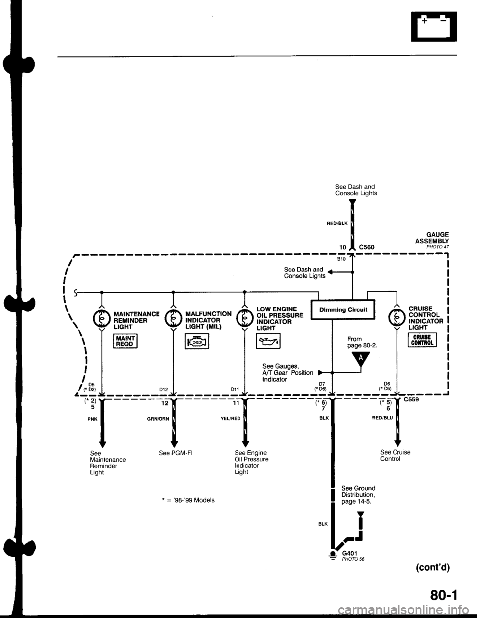
See Dash andConsole Lights
GAUGEASSEMBLY
(cont'd)
80-1
CRUISEcor{TRoL'NDICATONLIGHT
TcrurFlI cofnot I
r.ow ENGTNE IOIL PRESSURE IINDICATORLIGH'
I\YrlL:J
See Gauges,I'lT Gear PositionIndicator
"ff
I
See CrlControl
See GroundDistribution,page 14'5.
Y
I
.-t
G401PHO|O 56
T
li
'"1
See PGM'FI See Engineoil PressurelndicalorLight
* = '98-'�99 Modets
SeeMaintenanceReminderLight
\. I [,'d['*"' I il]i"fl".,B* I
i,1_* =i^ .l
'*f----l- :{
Page 1498 of 1681
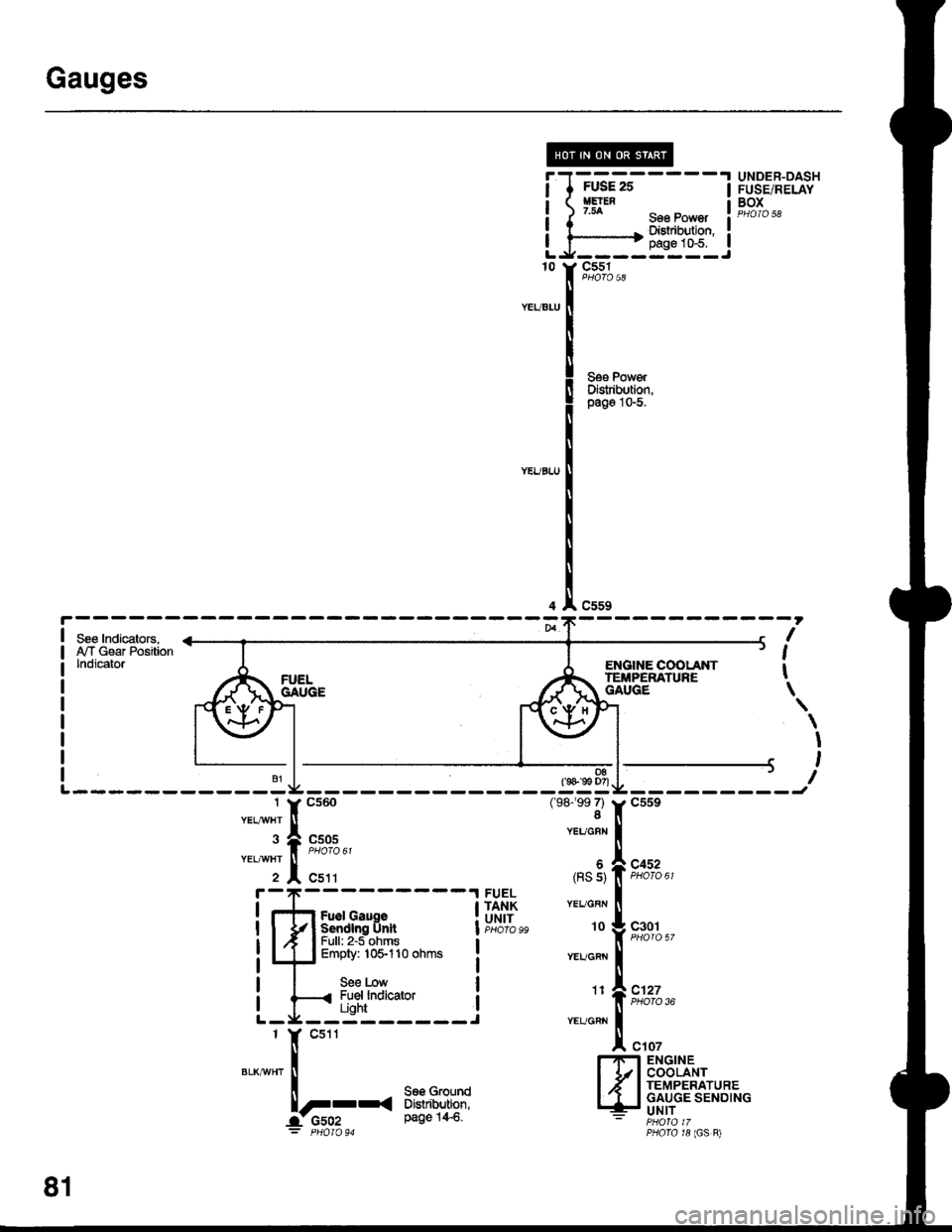
Gauges
I
I
I
I
10
FUSE 25HElEN7.54
FUSE/RELAYBOX
sse Power I eloro sa
Dishibution,:pags 1&5.----.----Jc551
c559
D8(s 99 D7)
(98-'�99 7)8
Seg PowerDistibution,pago l0-5.
ENGIIIE COOI-ANTTEIiPERATUNEGAUGE
I
I
t
\
\
I
,
I---------Jc559
c452PHOTO 61
c127PHOTO 36
c107
c505
c511
YEUGBN
(RS s)
YEL/GBN
10
YEUGRN
Fuel GaugeSendlng UnltFull: 2'5 ohmsEmpty: 10$110 ohms
See LowFuel lndicatorUght
FUELTANKUNITc301
11
YEUCRN
l.'n ENGINEI 1/l COOLANTI .' I TEMPERATUREI 'I I GAUGE SENDING.- UNIT- PHOfA 17PfiOrO r8 (GS B)
81
Page 1499 of 1681
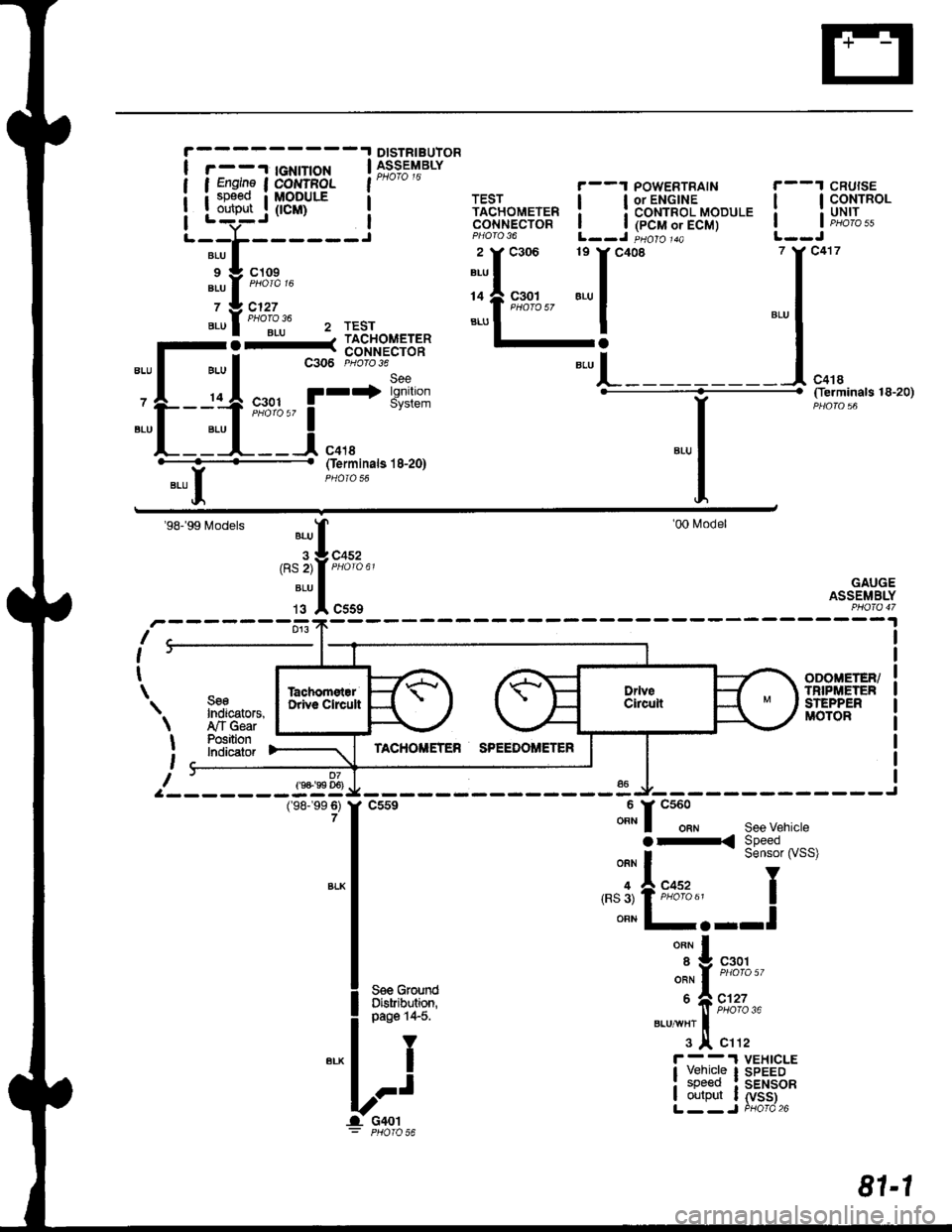
DISTRIBUIOR
r - -'l tGNtT|oN | 39;s;t'rarvI Engine I COI{TFOL l"* " "
i sp€ed i MoDULE a
Louteut .j (tcm) i
'-;t;----i
',i'l:i::'"
".ul""ollju 2 rEsr
-l-_1;.11=1==
-L-:ttt
'r*'i*'*
"-l
(ferminals 18-20)
YBLU II
Oerminals l8-20)
'98-'99 Models
r-------fr:fl;,,
'00l\4odel
GAUGEASSEMBLY
I
I
t
\
9-
SseIndicators,,ry'TGearPositionlndicatof
ODOIIETER/TNIPi,|:TENSTEPPERMOTOR
07f9+'99 D6)
\
I
t
I
(98-'�99 6)7
v------ -"u Jl,-------------J
f
csse ""t" f
"tt"t""
see vehicte
|
":^i:33i#'""'
I '.'3'tFffi"' I
I ""n l-.--l
|
*^l
| .^^^.^..-. ",',f n%',
l** ii*i
Lri ibr,li;tfi
81-1