G401 HONDA INTEGRA 1998 4.G Owner's Guide
[x] Cancel search | Manufacturer: HONDA, Model Year: 1998, Model line: INTEGRA, Model: HONDA INTEGRA 1998 4.GPages: 1681, PDF Size: 54.22 MB
Page 1277 of 1681
![HONDA INTEGRA 1998 4.G Owners Guide Moonroof
Circuit Diagram
\,
UNDER,HOOD FUSEi RELAY 8OX
No 41 (100A) N0.42 (40A)
IGNIT ON SW]TCH
M
MOONROOF M0TOR (Harchback)
BLK
G201G401
MOONROOF M0TOR (Sedan)
23-220 HONDA INTEGRA 1998 4.G Owners Guide Moonroof
Circuit Diagram
\,
UNDER,HOOD FUSEi RELAY 8OX
No 41 (100A) N0.42 (40A)
IGNIT ON SW]TCH
M
MOONROOF M0TOR (Harchback)
BLK
G201G401
MOONROOF M0TOR (Sedan)
23-220](/img/13/6069/w960_6069-1276.png)
Moonroof
Circuit Diagram
\,
UNDER,HOOD FUSEi RELAY 8OX
No 41 (100A) N0.42 (40A)
IGNIT ON SW]TCH
M
MOONROOF M0TOR (Harchback)
BLK
G201G401
MOONROOF M0TOR (Sedan)
23-220
Page 1278 of 1681
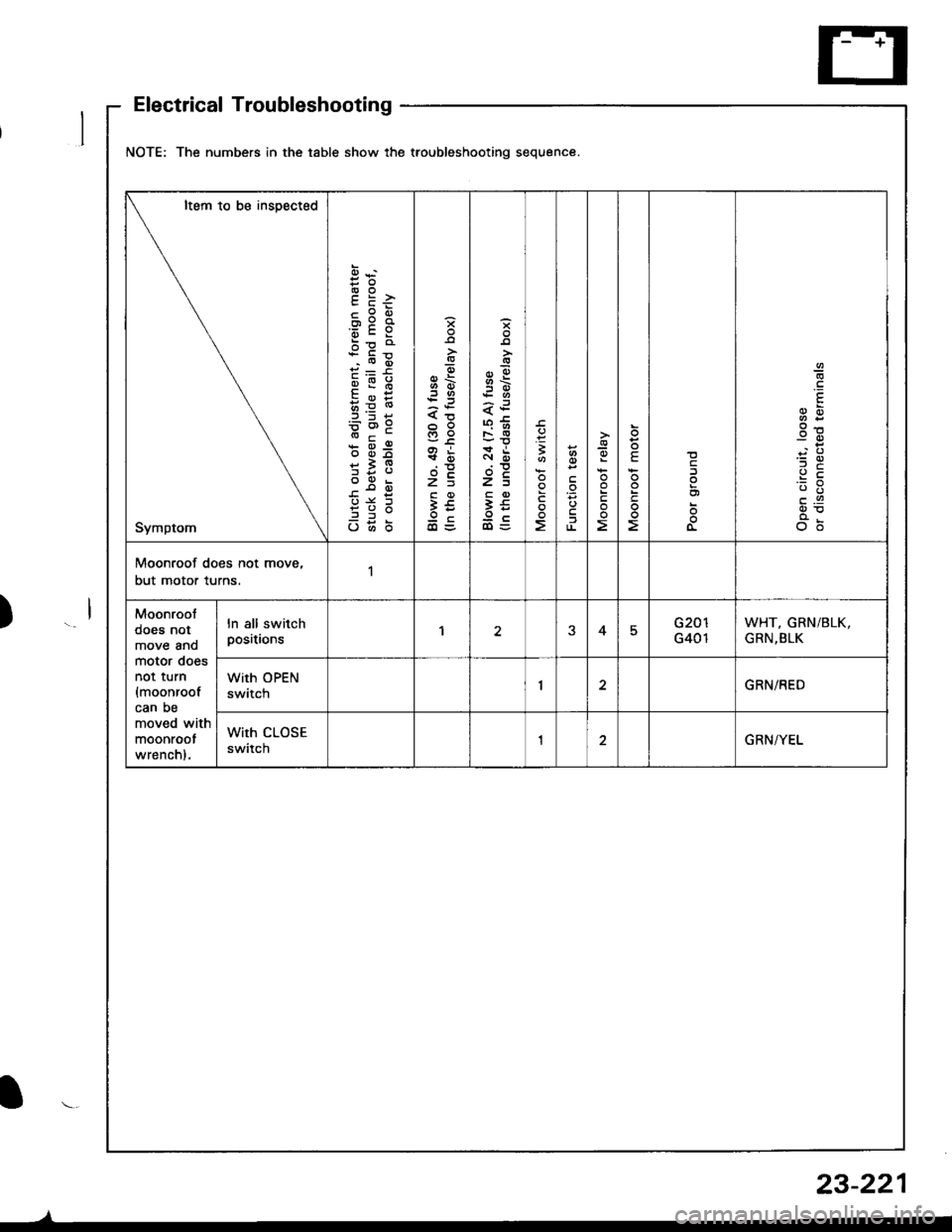
NOTE: The numbers in the table show the troubleshooting sequence.
Item to be insDected
Symptom
cPEox:a'6cY
bp o
qi:6
qE:
b=6'9
* d-9
*i9
?3;
o6b
H6
s
6\.:3
xi
t?c
3€oc
B
F
1
-9oE
!
E
3g
c.9
o6
Moonroof does not move,
but motor turns.1
Moonroot
does not
move anomotor doesnot turn
{moonroofcan be
moved with
moonroot
wrenchl.
ln all switchpositionsEG401
WHT, GRN/BLK,
GRN,BLK
With OPEN
swttcnGRN/RED
With CLOSE
swttcnGRN/YEL
Electrical Troubleshooting
23-221
I
Page 1288 of 1681
Troubleshooting
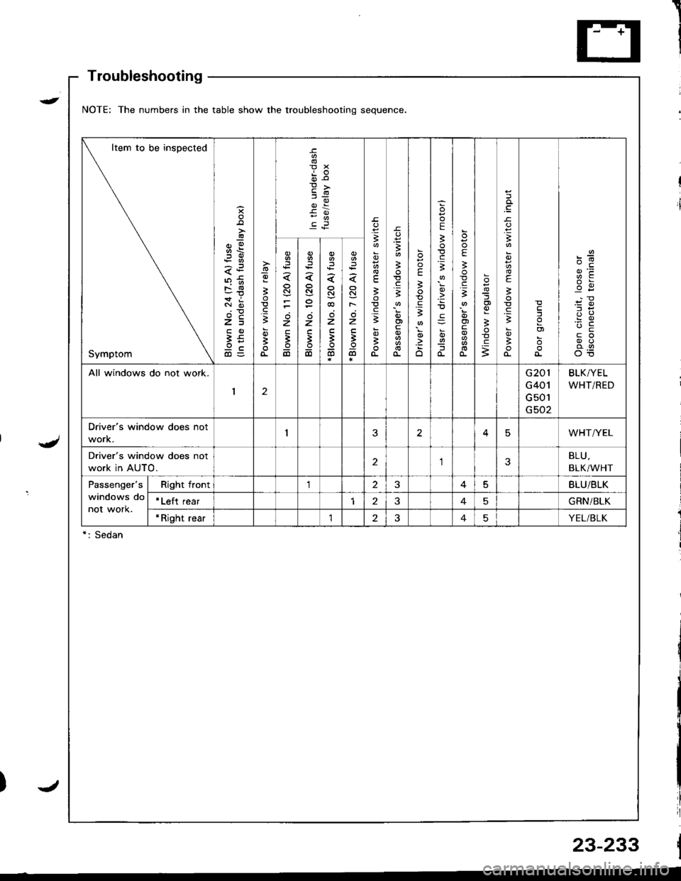
NOTE: The numbers in the table show the troubleshooting sequence
Item to be inspected
Symptom
;!
-!
z=
9cd)=
-9
3
;
oi
E
dr€
3
3
.=3
;
a
3
E.=3
E
;
;
.zo
E
3
.E3
!
o-
E
!.gi
oi
o-
og
3
c
.q
3
E
B
.gB
B
I
o)
c6z
3
6
N
z
;
6
z
'
6
N
F
z
B
@
All windows do not work.
12
G201
G401
G 501
G502
BLK/YEL
WHT/RED
Driver's window does not
work.25WHT/YEL
Driver's window does not
work in AUTO.23BLU,
BLK/WHT
Passenger's
windows do
not work.
Right front125BLU/BLK
*Left rear145GRN/BLK
*Right rear'lt?45YEL/BLK
*: Sedan
23-233
)t
Page 1298 of 1681
I,t
Troubleshooting
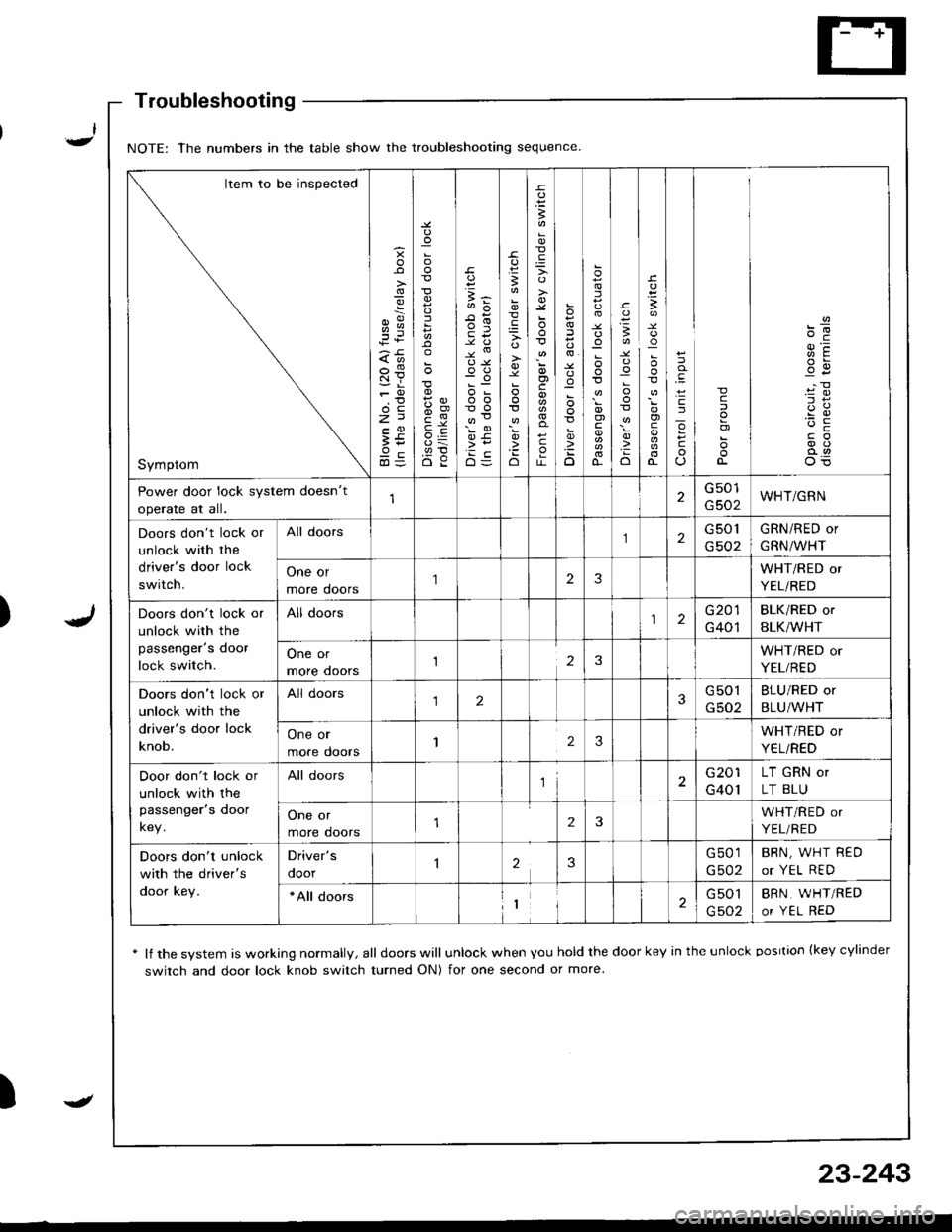
* lf the system is working normally, all doors will unlock when you hold the door key in the unlock oosrtion {key cylinder
switch and door lock knob switch turned ON) for one second or more
)
NOTE: The numbers in the table show the troubleshooting sequence
Item to be inspected
Symptom
g
;i
:
5
{,!
(,o
o-c
E5
B
'io
B
o)c
c
o
:
D
.uo
I
o)
o-
-c
:o
o
I
!
o)
cJ
o
c
c
o)
Power door lock system doesn't
operate at all.
G501
G502WHT/GRN
Doors don't lock or
unlock with the
driver's door lock
switch.
All doors2G 501
G502
GRN/RED or
GRN/WHT
One or
more doors
'I23WHT/RED or
YEL/RED
Doors don't lock or
unlock with the
passenger's door
lock switch.
All doors1G201
G401
BLK/RED or
BLK/WHT
One or
more ooors123WHT/RED or
YEL/RED
Doors don't lock or
unlock with the
driver's door lock
knob.
All doors123G501
G502
BLU/RED or
BLU/WHT
One or
more doors123WHT/RED or
YEL/RED
Door don't lock or
unlock with the
passenger's door
key.
All doorsl2G201
G401
LT GRN or
LT BLU
One or
more doors2WHT/RED or
YEL/RED
Doors don't unlock
with the driver's
door key.
Driver's
ooor23G501
G502
BRN, WHT REO
or YEL RED
*All doors1G 501
G502
BRN, WHT/RED
or YEL RED
-
23-243
Page 1300 of 1681
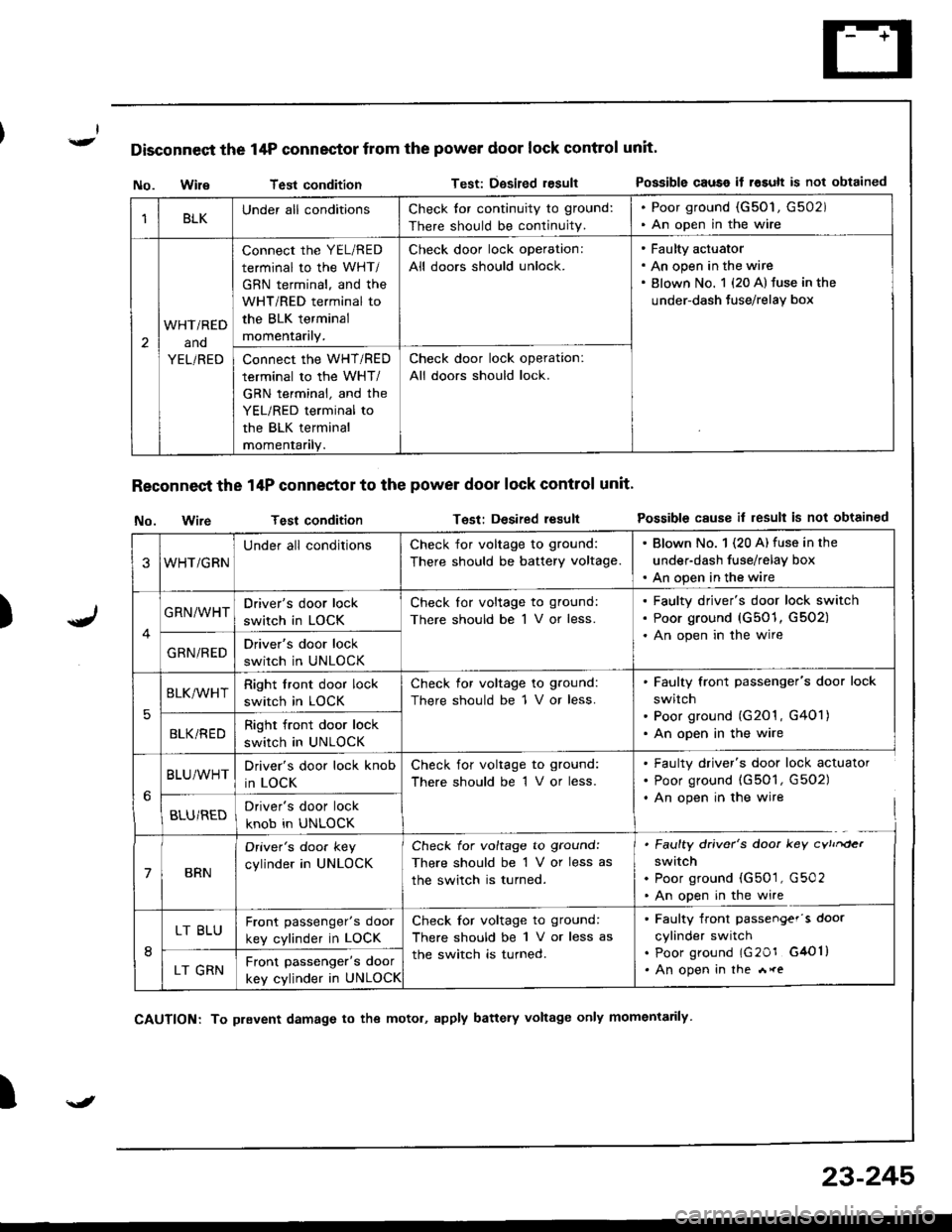
Disconnect the 14P connector from the power door lock control unit'
)
No. WileTest conditionTest: Dgsired resultPossible causo if rosult is not obtained
Reconnect the 14P conneetor to the power door lock control unit'
No. wireTest conditionTest: Desired resultPossible cause il result is not obtained
I
1BLKUnder all conditionsCheck tor continuity to ground:
There should be continuity.
. Poor ground (G50'1, G502). An open in the wire
2
WHTi RED
ano
YEL/RED
connect the YEL/RED
terminal to the WHT/
GBN terminal, and the
WHT/RED terminal to
the BLK terminal
momentarily.
Check door lock operation:
All doors should unlock.
Faulty actuator
An open in the wire
Blown No. 1 {20 A} fuse in the
under-dash Juse/relay box
Connect the WHT/RED
terminal to the WHT/
GRN terminal, and the
YEL/RED terminal to
the BLK terminal
momentanly.
Check door lock operation:
All doors should lock.
3WHT/GRN
Under all conditionsCheck for voltage to ground:
There should be battery voltage.
. Blown No. 1 (20 A) fuse in the
under-dash fuse/relay box. An open in the wire
GRN/WHTDriver's door lock
switch in LOCK
Check lor voltage to ground:
There should be 1 V or less.
Faulty driver's door lock switch
Poor ground (G501, G502)
An open in the wire
GRN/REDDriver's door lock
switch in UNLOCK
5
BLK/WHTRight front door lock
switch in LOCK
Check for voltage to ground:
There should be 1 V or less.
Faulty front passenger's door lock
switch
Poor ground (G201 , G401)
An open in the wireBLKi REDRight front door lock
switch in UNLOCK
BLU/WHTDriver's door lock knob
in LOCK
Check for voltage to ground:
There should be 1 V or less.
. Faulty driver's door lock actuator. Poor ground (G501, G502). An open in the wire
BLU/REDDriver's door lock
knob in UNLOCK
7BRN
Oriver's doo. key
cylinder in UNLOCK
Check for voltage to ground:
There should be 1 V or less as
the switch is turned.
. Faulty driver's door key cvtrrder
switch. Poor ground (G501, G502. An open in the wire
8
LT BLUFront passenger's door
key cylinder in LOCK
Check for voltage to ground:
There should be 1 V or less as
the switch is turned.
. Faulty front passengef's door
cylinder switch. poor ground lG20r G4Ol). An open in the *reLT GRNFront passenger's door
key cylinder in UNLOCK
\J
CAUTION: To prevent damage to the motol, apply battery voltage only momentarily
23-245
Page 1310 of 1681
![HONDA INTEGRA 1998 4.G Owners Guide Circuit Diagram
J
WNT/BLK +WHT
BLKYEL YEL/8LU
CABLEREEL
SET/BESUME1 SW]TCH
J
IGNITONCONTROLMODULE(cM)
LT
B lA
i,"YlDGBY
c
IT GRN/RED LTGRN/BLK
BLK
I
:
:2013401
III
I
VEHICLE SPEEDSENSOR (VSS)
M/T: CL HONDA INTEGRA 1998 4.G Owners Guide Circuit Diagram
J
WNT/BLK +WHT
BLKYEL YEL/8LU
CABLEREEL
SET/BESUME1 SW]TCH
J
IGNITONCONTROLMODULE(cM)
LT
B lA
i,"YlDGBY
c
IT GRN/RED LTGRN/BLK
BLK
I
:
:2013401
III
I
VEHICLE SPEEDSENSOR (VSS)
M/T: CL](/img/13/6069/w960_6069-1309.png)
Circuit Diagram
J
WNT/BLK +WHT
BLKYEL YEL/8LU
CABLEREEL
SET/BESUME1 SW]TCH
J
IGNITONCONTROLMODULE(cM)
LT
B lA
i,"'YlDGBY
c
IT GRN/RED LTGRN/BLK
BLK
I
:
:2013401
III
I
VEHICLE SPEEDSENSOR (VSS)
M/T: CLLTCH SWITCH \A/T:A,TGEARPostT oN swrc!(oN E].tr tr
8LK 8LK
lltl-0-_L-- --
G301 G2AlG401
UNDER-HOOD FUSEiFELAY BOXUNDEF DASH FUSEi RELAY BOX
lNDICATORL]GHT(0.91W)
BLU/RED
23-255
:?:'
ACC : ACCELERATIONOEC iDECELERATION
Page 1311 of 1681
t
t;
i'l
I
dil
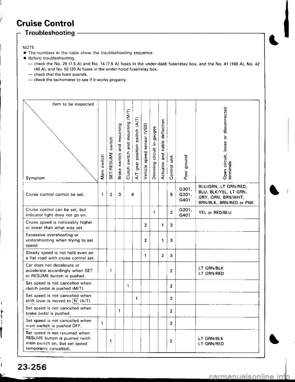
Gruise Gontrol
Troubleshooting
NOTE:
a The numbers in the table show the troubleshooting sequence.
a Belore troubleshooting,- check the No. 25 (7.5 A) and No. 14 (7.5 A) fusds in the under-dash fuse/relay box. and the No. 4l (100 A), No. 42(40 A), and No. 52 (20 A) fuses in the under-hood fuse/relay box.- check that the horn sounds.- check the tachometer to see if it works properly.
Item to be inspected
Symptom
c
:3
UJ
lU)(r
F(t
)
E
c
.
F
=
.g
E
-c
!-
Io
F
3
E
o)F
u)U'
co
_q.9-c
o)f,
ol
;l
E
.Eo
F
E
_9
)a
o
o-
o
c
.2
'::-c
OE
Cruise control cannot be set.15
G301
G201
G40't
BLU/GRN, LT GRN/RED.
BLU, BLKTYEL, LT GRN.
GRY, ORN, BRNiWHT,
BRN/BLK, BRNi RED or PNK
Cruise control can be set, but
indicator light does not go on.1G201
G401YEL or RED/BLU
Cruise speed is noticeably higher
or lower than what was set.1
Excessive overshooting or
undershooting when trying to set
speed
'I
Steadv soeed is not held even on
a flat road with cruise control set.1J
Car does not decelerate or
accelerate accordingly when SET
or RESUME button is pushed.
1LT GRN/BLK
LT GRN/RED
Set speed is not cancelled when
clutch pedal is pushed (M/T).1
Set speed is not cancelled when
shift lever is moved ro N (A/T).I
Set speed is not cancelled when
brake pedal is pushed.12
Set speed is not cancelled when
main switch is pushed OFF.
Set speed is not resumed whenRESUME button is pushed (with
main switch on, but set speedtemporarily cancelled).
2LT GRN/BLK
LT GRNiRED
23-256
Page 1313 of 1681
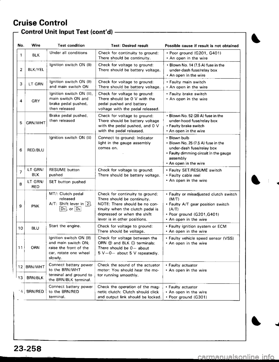
Cruise Control
- Control Unit InputTest(cont'dl
IBLKUnder all conditionsCheck for continuity to ground:
There should be continuity.
. Poor ground (G20l, G401). An open in the wire
2BLK/YEL
lgnition switch ON {ll}Check for voltage to ground:
There should be battery voltage.
. Blown No. l4 (7.5 Alfuse in the
under-dash fuse/relay box. An open in the wire
3LT GRNlgnition switch ON (ll)
and main switch ON
Check for voltage to ground:
There should be battery voltage.
. Faulty main swjtch. An open in the wire
GRY
lgnition switch ON (ll),
main switch ON and
brake pedal pushed,
then released
Check for voltage to ground:
There should be O V with the
pedal pushed and battery
voltage with the pedal released.
. Faulty brake switch. An open in the wire
5GRN/WHT
Brake pedal pushed,
then released
Check for voltage to ground:
There should be battery voltage
with the pedal pushed, and 0 V
with the pedal released.
Blown No. 52 (20 A)fuse in the
under-hood fuse/relay box
Faulty brake switch
An open in the wire
6RED/BLU
lgnition switch ON (ll)Connect to ground: lndicator
light in the gauge assembly
comes on.
Blown bulb
Blown No. 25 (7.5 A)fuse in the
under-dash fuse/relay box
Faulty dimming circuit in the gauge
assembly
An open in the wire
7LT GRN/
BLK
RESUME button
pushed
Check tor voltage to ground:
There should be battery voltage.
Faulty SET/RESUME switch
Faulty cable reel
An open in the wire8LT GRN/
RED
SET button pushed
IPNK
MT/: Clutch pedal
released
A/Tr Shift lever in [2l,
[Dl]. o, [o'l
-
Check for continuity to ground:
There should be continuity.
NOTE: There should be no con-
tinuity when the clutch pedal is
depressed or when the shift
lever is in other positions.
Faulty or misadjusted clutch switch(M/T)
Faulty A/T gear position switch(A/T)
Poor ground (G201,G401)
An open in the wire
't0BLUStart the engine.Check lor voltage to ground:
There should be voltage.
. Faulty ignition system or ECM. An open in the wire
't1ORN
lgnition switch ON (ll)
and main switch ON;
raase the front of the
car, rotate one wheel
slowly.
Check for voltage between the
ORN @ and BLK O terminals:
There should be 0- about
5 V-O- about 5 V repeatedly.
. Faulty vehicle speed sensor {VSS). An open in the wire
BRN/WHTConnect battery power
to the BRN/WHT
terminal and ground to
the BRN/BLK terminal.
Check the sound of the actuator
motor: You should hear the mo-
tor running smoothly.
. Faulty actuator. An open in the wire
BRNi BLK
Connect battery power
to the BRN/RED
Iermrnal.
Check the operation of the mag-
netic clutch: Clutch should click
and output link should be locked.
Faulty actuator
An open in the wire
Poor ground (G30'l)
No. Wire Test conditionTest: Desiled result Possible cause il lesult is not obtained
' 4 I BRN/RED
{
{
23-258
-L
Page 1321 of 1681
![HONDA INTEGRA 1998 4.G Owners Guide (
Wipers/Washers
Circuit Diagram
UNDEF.OASHFUSEiRELAYSOX
NTE NMI]TEIIIWPES RELAYCIFCUIT/ In lhe inr6grar6d \ @nlrolun( I
IGNITIONSW TCHUNDER,HOOD FUSE/RELAY BOX
GRI]/BLK
GFIVBLK
WINDSHIELO WPENJWASHE HONDA INTEGRA 1998 4.G Owners Guide (
Wipers/Washers
Circuit Diagram
UNDEF.OASHFUSEiRELAYSOX
NTE NMI]TEIIIWPES RELAYCIFCUIT/ In lhe inr6grar6d \ @nlrolun( I
IGNITIONSW TCHUNDER,HOOD FUSE/RELAY BOX
GRI]/BLK
GFIVBLK
WINDSHIELO WPENJWASHE](/img/13/6069/w960_6069-1320.png)
(
Wipers/Washers
Circuit Diagram
UNDEF.OASHFUSEiRELAYSOX
NTE NMI]TEI'IIWPES RELAYCIFCUIT/ In lhe inr6grar6d \ @nlrolun( I
IGNITIONSW TCHUNDER,HOOD FUSE/RELAY BOX
GRI]/BLK
GFIVBLK
WINDSHIELO WPENJWASHER SWITCH
BLK
G201G401
* : Wilh combined washer-wiDer ooeralion
BLI(GRN
I
A w'',,os"( M ) WASHER
Y
MoroF
8LK
I
G301
23-266
I
Page 1322 of 1681
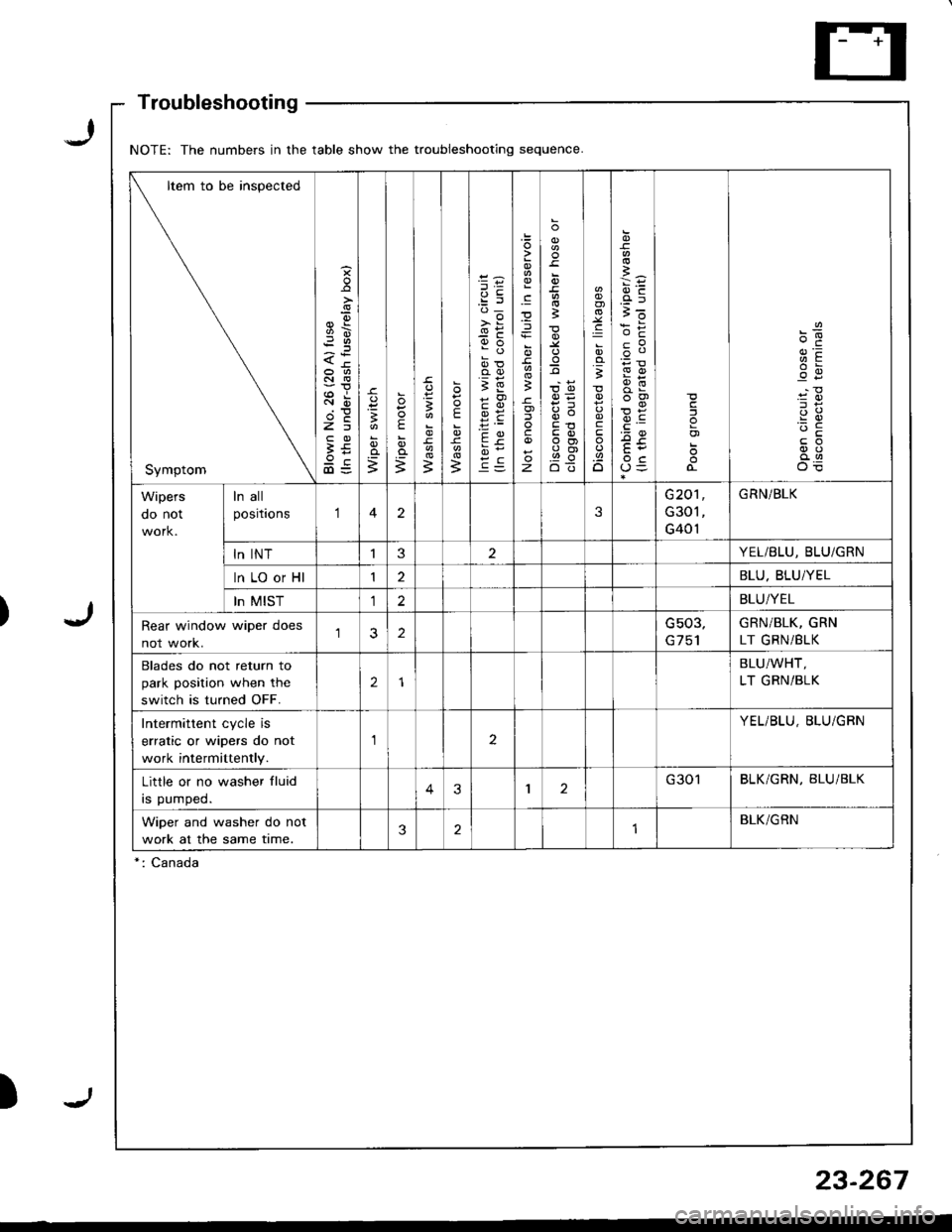
NOTE: The numbers in the table show the troubleshooting sequence
Item to be inspected
Symptom
s
9\
<-tr
Rir
2E
3E9c@=
o=
;
E
;3
E
B
e:'d_
>i
9o
oo
;E
9E
c
).E
z
o
3
;
t,o
q(')
E3ot
.g
;
c
.9.o
i6
cP
F!
o3cj
o)
Wipers
oo nor
ln all
positaons123
G20'l
G301
G401
GRN/BLK
ln INTI3YEL/BLU, BLU/GRN
ln LO or Hl12BLU. BLU/YEL
In MIST12BLU/YEL
Rear window wiper does
not work.2Gs03,GRN/BLK, GRN
LT GRNi BLK
Blades do not return to
park position when the
switch is turned OFF.
2
BLU/WHT,
LT GRN/BLK
Intermittent cycle is
erratic or wipers do not
work intermittently.
aYEL/BLU, BLU/GBN
Little or no washer fluid
rs pumped.43I2G301BLK/GRN, BLU/BLK
Wiper and washer do not
work at the same time.321BLK/GRN
*: Canada
Troubleshooting
23-267