G401 HONDA INTEGRA 1998 4.G User Guide
[x] Cancel search | Manufacturer: HONDA, Model Year: 1998, Model line: INTEGRA, Model: HONDA INTEGRA 1998 4.GPages: 1681, PDF Size: 54.22 MB
Page 1119 of 1681
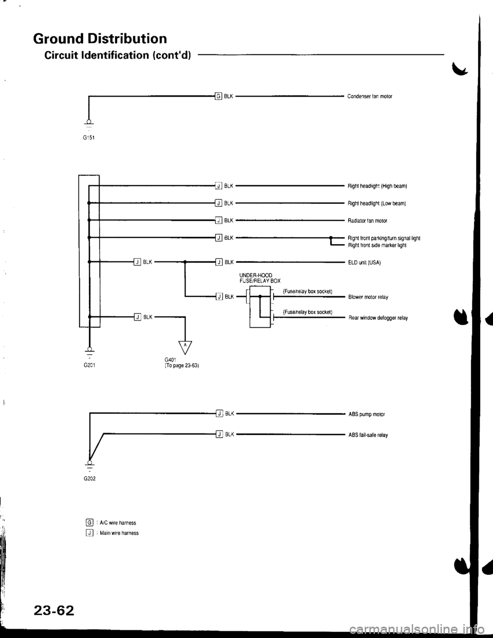
Ground Distribution
Circuit ldentification (cont'd)
Condenser laf molor
8LK
BLK
BLK
Righl headlighl (High beam)
Righl headlighl (Low beam)
Badiator lan molor
'LK ------
li;li fil Hi l'iff il"1"'"'
ELD unit (USA)
UNDER.HOODFUSE/RELAY BOX
: {Fuse/relayboxsockel)Blower molor relay
, (Fuseirelayborsochel)iear wnoow oerogger reray
G201
"--l-
VG401(To page 23-63)
AgS pump motor
ABS lailsale relay
@ , ac,nir" n",n"..
U Malnwire harness
23-62
Page 1132 of 1681
![HONDA INTEGRA 1998 4.G User Guide Circuit Diagram (M/Tl
tJ
STARTEBCUT RELAY
)/
ll-G2o1G401
rAa rtFz5- r3
) -rr
CLUTCHINTERLOCKSW]TCH
IGNITIONX SWITCH
!_*",.^-*-G-l
"T"
BTKWHT BLKWHT
llr - tr |
BLKFED 8LU/BLK
- BLK,BE I__-lrror.oo*
I HONDA INTEGRA 1998 4.G User Guide Circuit Diagram (M/Tl
tJ
STARTEBCUT RELAY
)/
ll-G2o1G401
rAa rtFz5- r3
) -rr
CLUTCHINTERLOCKSW]TCH
IGNITIONX SWITCH
!_*",.^-*-G-l
"T"
BTKWHT BLKWHT
llr - tr |
BLKFED 8LU/BLK
- BLK,BE I__-lrror.oo*
I](/img/13/6069/w960_6069-1131.png)
Circuit Diagram (M/Tl
tJ
STARTEBCUT RELAY
)/
ll-G2o1G401
rAa rtFz5- r3
) -rr
CLUTCHINTERLOCKSW]TCH
IGNITIONX SWITCH
!_*",.^-*-G-l
"T"
BTKWHT BLKWHT
llr - tr |
BLKFED 8LU/BLK
- BLK,BE' I__-lrror.oo*
I I
+Yffii'"'Tf'o' | |
u"T-l
i,t^il'r** | |
=-T--. I
twt t
l$*Tl r
IA II
BLK
tY--lt I-|ffim-
|
rl
UNDEB HOOD FUSE/BELAY BOX
No 41 (100A) N0.42 (404)
Page 1174 of 1681
![HONDA INTEGRA 1998 4.G User Guide Circuit Diagram (Without A/Cl
UNOEF.OASHFUSE,NELAY BOX
|-;ffi;I-YELf\-.rl]-t
BTKEL -l
RAOIATORFANS\,YITCHfoN : above )(199F (93C)J
BLIVREO
BLK
I
G201G401
IGNITION SWITCH
N0.41 (lmAl No.42 (104)
RAD HONDA INTEGRA 1998 4.G User Guide Circuit Diagram (Without A/Cl
UNOEF.OASHFUSE,NELAY BOX
|-;ffi;I-YELf\-.rl]-t
BTKEL -l
RAOIATORFANS\,YITCHfoN : above )(199F (93C)J
BLIVREO
BLK
I
G201G401
IGNITION SWITCH
N0.41 (lmAl No.42 (104)
RAD](/img/13/6069/w960_6069-1173.png)
Circuit Diagram (Without A/Cl
UNOEF.OASHFUSE,NELAY BOX
|-;ffi;I-YELf\-.rl]-t
BTK'EL -l
RAOIATORFANS\,YITCHfoN : above )(199'F (93'C)J
BLIVREO
BLK
I
G201G401
IGNITION SWITCH
N0.41 (lmAl No.42 (104)
RADIATORFANRELAY
23-117
.l
Page 1181 of 1681
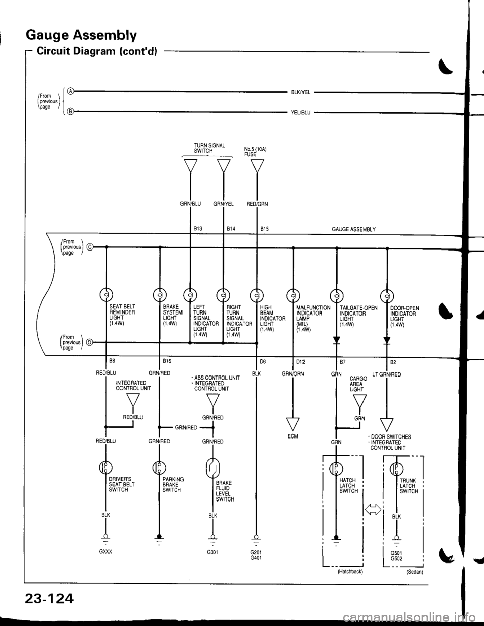
auge Assembly
Circuit Diagram (cont'dl
iG
BLK,IYEL
No.5 (10A)
V
IREO/GRN
I e,s
TURN SIGNALSWITCN
v--=v
tltl
tlGBN/BLIJ GRN,YEL
lltl
I e's I s,o
"i.uv"'T""
H^,J.**.GBN . INTEGRATEO
I coNrRor uNrT
,'T--l ffi--l
lI*ni lI*i
il i*i t i
i. li;, I
L__ i L:'�_" i(Hatchback) (Sedan)
| 012
GRNORN
vECM
louBLK
G20lG401
RIGNTTURNSIGNALINDICATORL]GHT(1.4w)
TAILGATE.OPENINDICATORLIGHT(1.4!9
RED/BLU GBN/RED| | . ABS CoN-FOL U\lTI .NTEGFATED I .INTEGBATED
|
*v^"
|
-'v*
| .roL-" I or*frro
ts Fo.''-,,-jBED/BLU GRN/RED GHNi RED
rrl
AAA
Yu'**- Y*,,r" Y**
l3$i;.?.'' 13ffi3- ll#,
| | l!i,Iib'.
TIT:-_:
GXXX G3O1
23-124
Page 1182 of 1681
J
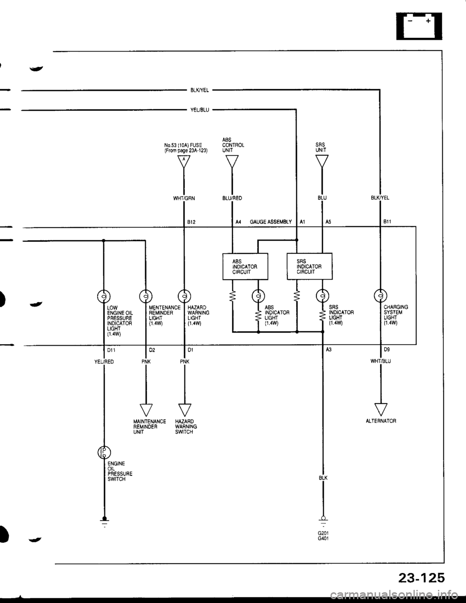
BLKYEL
YEUBLU
A8SN0.53 (104) FUSE CONTROLlFrofi page 23A'123) UNIT
VV
II
tltlWHT/GFN BLU/REO
lonWHT€IU
I
I
I
\?
ALTERNATOR
lo'PNK
J
HAZAROWARNINGswtTcH
MENTENANCEREMINDERLIGHT0.4v,/i
lo'PNK
II
I
J
MAINTENANCEREMINDERUNIT
| 011
YEUREO
I
T
P"-:
)-
BLK
I:
G201G401
LOWENGINE OILPFESSUREINDICATORLIGHT0.4w)
23-125
)J
Page 1195 of 1681
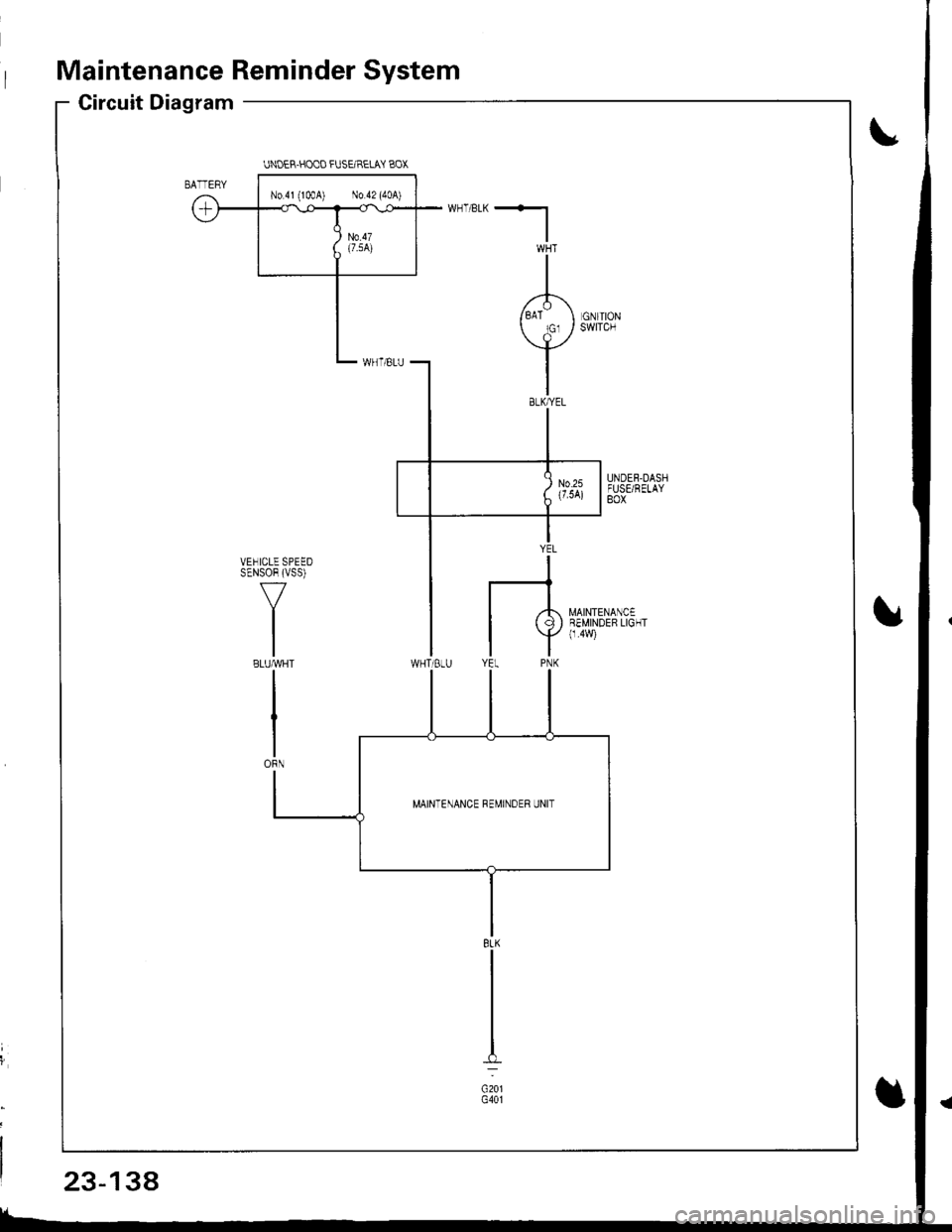
Maintenance Reminder System
Circuit Diagram
UNOER.HOOO FUSEIRELAY BOX
N0.41 (lmA) No 42 (40A)
MAINTENANCE REMINDER UNIT
8LK
c201G401
23-138
Page 1196 of 1681
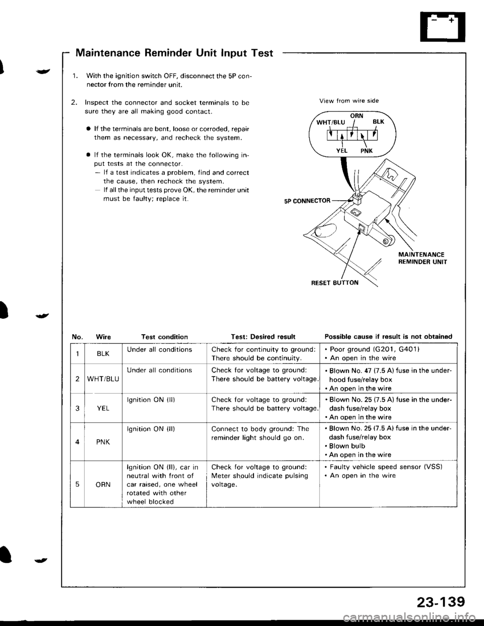
Maintenance Reminder Unit Input Test
)
v
t
1.With the ignjtion switch OFF, disconnect the 5P con-
nector from the reminder unit.
Inspect the connector and socket terminals to be
sure they are all making good contact.
a lf the terminals are bent, loose or corroded, repair
them as necessary, and recheck the system.
a lf the terminals look OK, make the following in-
put tests at the connector.- lf a test indicates a problem, find and correct
the cause, then recheck the system.
lf all the input tests prove OK, the remind€r unit
must be faulty; replace it.
2.View from wire side
MAINTENANCEREMINDER UNIT
No.WileTest conditionTest: Dosired resultPossible cause it lesult is not obtained
ORN
IBLKUnder all conditionsCheck for continuity to ground:
There should be continuity.
. Poor ground (G201, G4011. An open in the wire
2WHT/BLU
Under all conditionsCheck for voltage to ground:
There should be battery voltage
. Blown No. 47 (7.5 A) fuse in the under-
hood fuse/relay box. An open in the wire
3YEL
lgnitionONflr)Check lor voltage to ground:
There should be battery voltage.
. Blown No.25 {7.5 A) fuse in the under-
dash fuse/relay box. An open in the wire
4PNK
lgnition ON {ll)Connect to body ground: The
reminder light should go on.
Blown No.25 (7.5 Alfuse in the under-
dash fuse/relay box
Blown bulb
An open in the wire
5ORN
lgnition ON (ll), car in
neutral with front of
car raised, one wheel
rotated with other
wheel blocked
Check for voltage to ground:
Meter should indicate pulsang
voltage.
. Faulty vehicle speed sensor (VSS)
. An open in the wire
t
23-139
Page 1198 of 1681
![HONDA INTEGRA 1998 4.G User Guide Circuit Diagram
)
{
{
I
UNDER-HOOD FUSEiRELAY 80XIGN TIONSWITCHUNDER-DASHFUSE/RELAY BOX
. TRANSMISS]ONCONTROLMODULE (TCM)
/;; l-^--;;;;lw--BLh ---wrl f ,:+ BLK/E- t.d\o-ft\---l
I t,;:*
IVECM
f7
ILT HONDA INTEGRA 1998 4.G User Guide Circuit Diagram
)
{
{
I
UNDER-HOOD FUSEiRELAY 80XIGN TIONSWITCHUNDER-DASHFUSE/RELAY BOX
. TRANSMISS]ONCONTROLMODULE (TCM)
/;; l-^--;;;;lw--BLh ---wrl f ,:+ BLK/E- t.d\o-ft\---l
I t,;:*
IVECM
f7
ILT](/img/13/6069/w960_6069-1197.png)
Circuit Diagram
)
{
{
I
UNDER-HOOD FUSEiRELAY 80XIGN TIONSWITCHUNDER-DASHFUSE/RELAY BOX
. TRANSMISS]ONCONTROLMODULE (TCM)
/;; l-^--;;;;lw--BLh ---wrl f ,:+ BLK/E- t.d\o-ft\---l
I t,;:'*'
IVECM
f7
ILT GRN/BLK
YEUBLU
(n lhe gauqe assembly)D4
TRANSMISSIONCONTROLMODULErrcM)
f7
IIGRN/BLK
c6c7c8 lc9NTERLOCKCONTROLUNIT (
f7
IGRNMHT
BLK
TRANSMISSION CONTROLMODULE TICM)GRNCRN]BLULTGRNMHT
GRN/YEL
No l9 (104)FUSE
f7
IRED/BLK
A?TGEARPOSITION SWTCHRED
II
I
Y?
DASH LIGHTSBFIGHTNESSCONTROLLER
BLK
oro,G40lG20lG401
A/T GEAH POSITION NDICATOR DIMMING C RCUIT
A/T GEARPOS TIONCONSOLELIGHT(1.4w)
/ ,/ t2
{,
23-141
Page 1200 of 1681
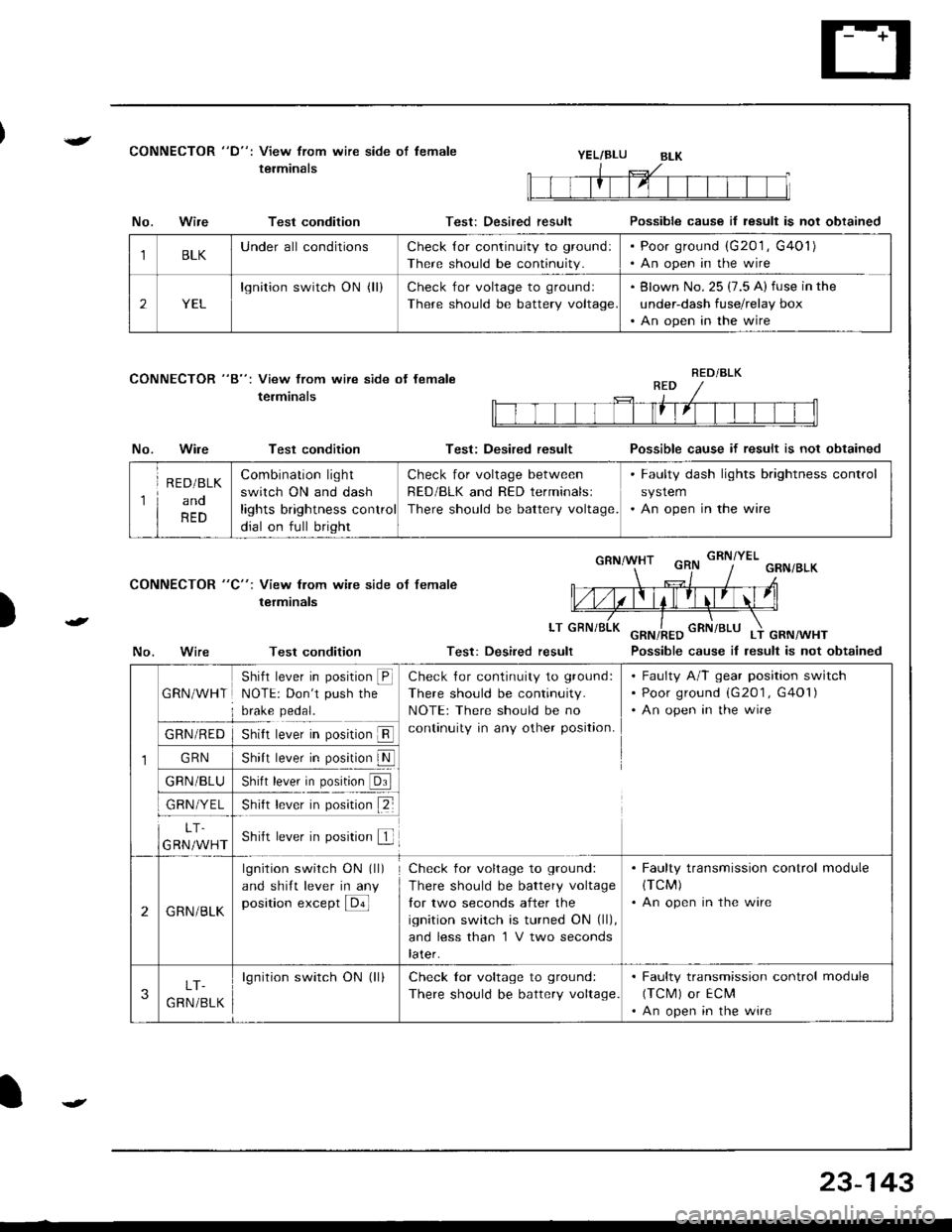
{CONNECTOR "D": View from wire side of lemale
terminalsYEL/BLU
CONNECTOR "8": View from wire side ot female
terminals
No.Wire
No.Wire
Test condition
Test condition
Test condition
Test: Desired result
Test: Desired result
Possible cause il result is not obtained
Possible cause if result is not obtained
Possible cause iI lesult is not obtained
)
CONNECTOR "C": View from wile side ot female
terminals
LT
No.Test: Desired result
1BLKUnderall conditionsCheck {or continuity to ground:
There should be continuity.
Poor ground (G201 , G401)
An open in the wire
2YEL
lgnition switch ON (ll)Check for voltage to groundl
There should be battery voltage
Blown No. 25 (7.5 A) fuse in the
under-dash fuse/relay box
An open in the wire
RED/BLK
1
R E D/BLK
ano
RED
Combination light
switch ON and dash
lights brightness control
dial on full bright
Check for voltage between
RED/BLK and RED terminalsl
There should be battery voltage.
. Faulty dash lights brightness control
system. An open in the wire
1
GRN/WHT
Shifl lever in position @NOTE: Don't push the
brake pedal.
Check {or continuity to ground:
There should be continuity.
NOTE: There should be no
continuity in any other position.
Faulty A/T gear position switch
Poor ground (G201 , G401)
An open in the wire
GRN/RED
GRN
GRN/BLU
GRN/YEL
5nrrI rever In pos[ron ll
shl, b*|' il. p"1,!lN
)nrn rever In posrron url
snt r""-. r p*;ir" tZ-
LT.
GRN/WHTShift lever in position f
2GRN/BLK
lgnition switch ON (ll)
and shift lever in any
position except E
Check for voltage to ground:
There should be battery voltage
lor two seconds after the
ignition switch is turned ON (ll),
and less than 'l V two seconds
later.
. Faulty transmission control module(TCM)
. An open in the wire
3LT-
G RN /BLK
lgnition switch ON (ll)Check lor voltage to ground:
There should be battery voltage.
. Faulty transmission control module
(TCM) or ECM'An open in the wire
23-143
Page 1206 of 1681
){r/
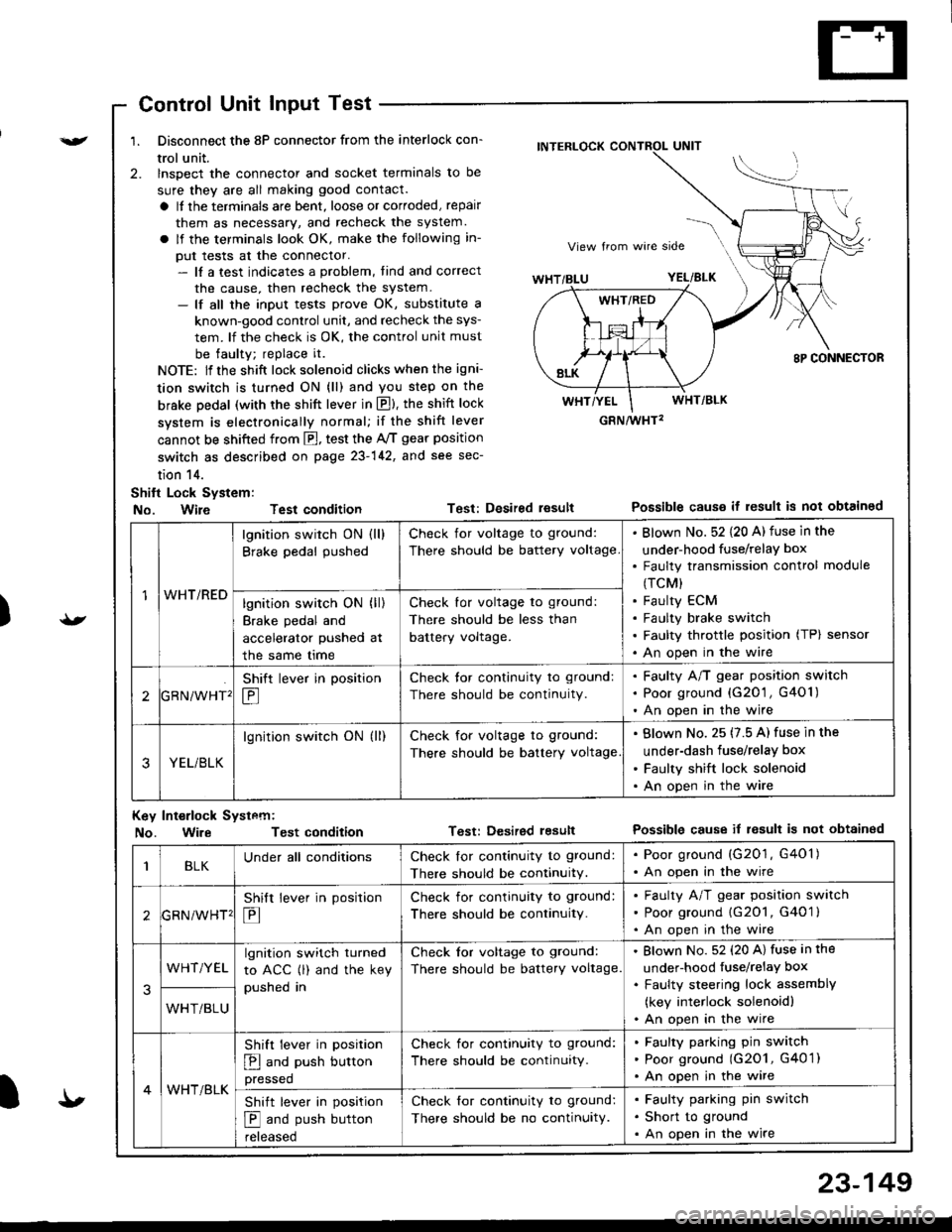
Control Unit Input Test
1. Disconnect the 8P connector from the interlock con-
trol unit.
2. lnspect the connector and socket terminals to be
sure they are all making good contact.
a It the terminals are bent, loose or corroded, repair
them as necessary, and recheck the system.
a lf the terminals look OK, make the following in-
put tests at the connector.- lf a test indicates a problem, tind and correct
the cause, then recheck the system.- lf all the input tests prove OK, substitute a
known-good control unit, and recheck the sys-
tem. lf the check is OK, the control unit must
be faulty; replace it.
NOTE: lf the shift lock solenoid clicks when the igni-
tion switch is turned ON (ll) and you step on the
brske Dedal (with the shift lever in E). the shift lock
system is electronically normal; if the shift lever
cannot be shifted from fl, test the 46 gear position
switch as described on page 23-142, and see sec-
tion 14.
Shift Lock System:
No. Wire Test condition
No. WireTest condition
Test: Desired resultPossible causs it result is not obtained
Test: Dcsired lesultPossible cause it result is not obtainsd
INTERLOCK CONTROL UNIT
GRN/wHT2
1WHT/RED
lgnition switch ON (ll)
Brake pedal pushed
Check for voltage to ground:
There should be battery voltage
Blown No. 52 {20 A) fuse in the
under-hood fuse/relaY box
Faulty transmission control module
(TCM)
Faulty ECM
Faulty brake switch
Faulty throttle position (TP) sensor
An open in the wire
lgnition switch ON (ll)
Brake pedal and
accelerator pushed at
the same me
Check for voltage to ground:
There should be less than
battery voltage.
tGRN/WHT'
Shift lever in position
E
Check tor continuity to ground:
There should be continuity.
Faulty A/T gear position switch
Poor ground {G20'1 , G401)
An open in the wire
3YEL/BLK
lgnition switch ON (ll)Check for voltage to ground:
There should be battery voltage
Blown No. 25 (7.5 A) fuse in the
under-dash fuse/relay box
Faulty shift lock solenoid
An open in the wire
Key Int€rlock Systcm:
BLKUnder all conditionsCheck lor continuity to ground:
There should be continuitY.
. Poor ground (G201, G401). An open in the wire
GRNiWHT'
Shift lever in position
E
Check for continuity to ground:
There should be continuity.
Faulty A/T gear position switch
Poor ground {G2O1, G401 }
An open in the wire
3
WHT/YELlgnition switch turned
to ACC (l) and the key
pushed in
Check tor voltage to ground:
There should be battery voltage.
Blown No. 52 (20 A) fuse in the
under-hood fuse/relaY box
Faulty steering lock assemblY
(key interlock solenoidl
An open in the wireWHT/BLU
4WHT/BLK
Shift lever in position
E and push button
pressed
Check for continuity to ground:
There should be continuity.
Faulty pafking pin switch
Poor ground (G2O1, G4O 1)
An open in the wire
Shift lever in position
E and push button
reteaseo
Check for continuity to ground:
There should be no continuity.
Faulty parking pin switch
Short to ground
An open in the wire
I'
23-149