Transmission HONDA INTEGRA 1998 4.G Manual PDF
[x] Cancel search | Manufacturer: HONDA, Model Year: 1998, Model line: INTEGRA, Model: HONDA INTEGRA 1998 4.GPages: 1681, PDF Size: 54.22 MB
Page 578 of 1681
Transmission
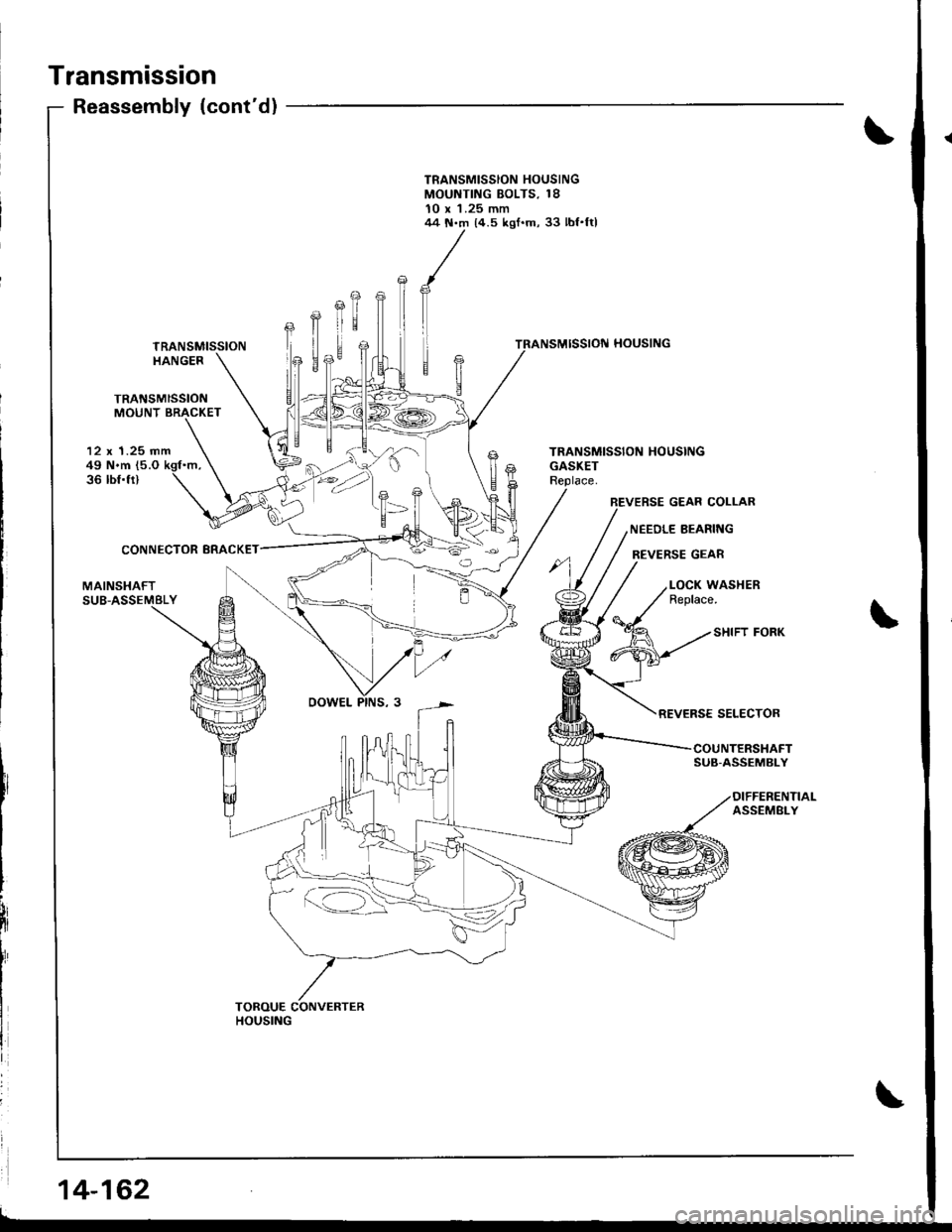
TRANSMISSIONMOUNT BRACKET
Reassembly (cont'd)
TRANSMISSIONHANGER
Efr
E
12 x 1.25 mm49 N.m (5.O
36 tbf.fr)
CONNECTOR BRACKET
NEEDLE BEARII{G
REVERSE GEAR
MAINSHAFT
SHIFT FORK
REVERSE SELECTOR
SUB-ASSEMBLY
14-162
r=-42
TOROUE CONVERTERHOUSING
TRANSMISSION HOUSINGMOUNTING BOLTS, 1810 x 'l.25 mm44 N.m 14.5 kgf.m, 33 lbf.ftl
TRANSMISSION HOUSINGGASKET
BEVERSE GEAR COLLAR
LOCK WASHERReplace.
I
Page 579 of 1681
![HONDA INTEGRA 1998 4.G Manual PDF 18. Install the sub-shaft assembly in the transmission
housing {see page 14-142],.
19. Install the reverse idler gear and gear shaft holder(see page 14-158).
20. Install the differential assembly in HONDA INTEGRA 1998 4.G Manual PDF 18. Install the sub-shaft assembly in the transmission
housing {see page 14-142],.
19. Install the reverse idler gear and gear shaft holder(see page 14-158).
20. Install the differential assembly in](/img/13/6069/w960_6069-578.png)
18. Install the sub-shaft assembly in the transmission
housing {see page 14-142],.
'19. Install the reverse idler gear and gear shaft holder(see page 14-158).
20. Install the differential assembly in the torque con
verter housrng.
21. Assemble the mainshaft and countershaft sub-
assembly, then install them together in the torque
converler noustng.
22. Turn the shilt fork so the large chamlered hole is fac-
ing the fork bolt hole, then installthe shift tork with
the reverse selector and torque the lock bolt. Bend
the lock tab against the bolt head.
SHIFT FORK
23. Install the reverse gear with the collar and needte
bearing on the countershaft.
24. Align the spring pin of the control shaft with the
transmission housing groove by turning the control
shaft.
25. Place the transmission housing on the torque con-
verter housing with a new gasket and the three
dowel pins.
CONTROL
TRANSMISSION HOUSING
lnstall the transmission housing mounting bolts along
with the transmission hanger and the connector
bracket, then torque the bolts in two or more steps
in the sequence shown.
TOROUE: rt4 N'm (4.5 kgt.m, 33 lbt.lt)
TRANSMISSION
26.
LOCK WASHERReplace.
6 x 1.0 mm4 t{.m(1.4 kgf.m, 10
e
Large chamfered hole
/ -'K\,,
a
14-163
Page 580 of 1681
Transmission
SUB.SHAFT
MAINSHAFT
Reassembly {cont'd)
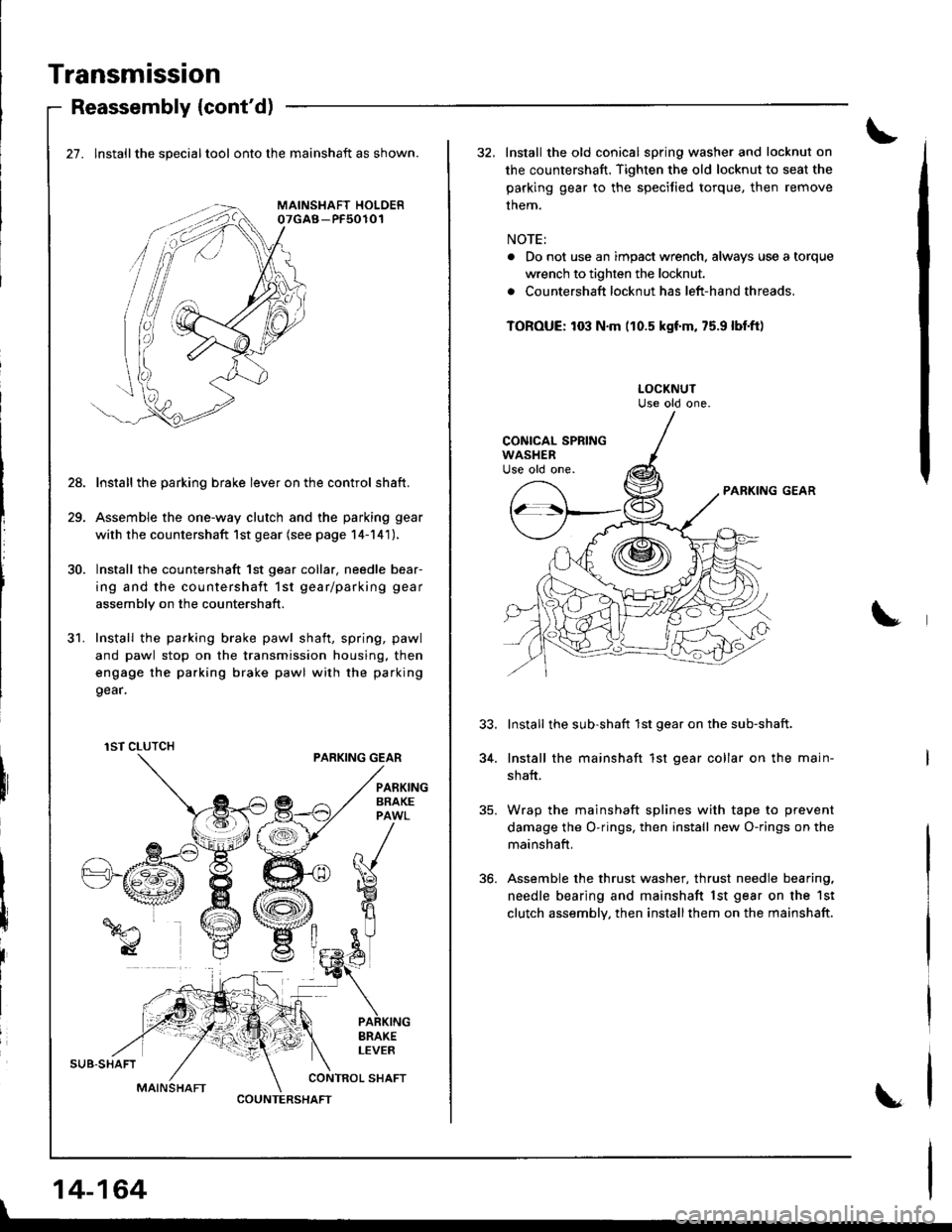
27. lnstallthe specialtool onto the mainshaft as shown.
Install the parking brake lever on the control shaft.
Assemble the one-way clutch and the parking gear
with the countershaft 1st gear (see page 14-141),
Install the countershaft 1st gear collar. needle bear-
ing and the countershaft 1st gear/parking gear
assembly on the countershaft.
Install the parking brake pawl shaft, spring, pawl
and pawl stop on the transmission housing. then
engage the parking brake pawl with the parking
9ear.
PARKING GEAR
28.
31.
I
I
iIBRAKELEVER
CONTROL SHAFT
1ST CLUTCH
COUNTERSHAFT
|
14-164
32, Install the old conical spring washer and locknut on
the countershaft. Tighten the old locknut to seat the
parking gear to the speciJied torque, then remove
them.
NOTE:
. Do not use an impact wrench, always use a torque
wrench to tighten the locknut.
. Countershaft locknut has left-hand threads,
TOROUE: to3 N.m (10.5 kgf'm, 75.9 lbl.ft)
PARKING GEAR
Install the sub-shaft 1st gear on the sub-shaft.
Install the mainshaft 1st gear collar on the main-
shaft.
Wrap the mainshaft splines with tape to prevent
damage the O-rings, then install new O-rings on the
mainshaft,
Assemble the thrust washer, thrust needle bearing,
needle bearing and mainshaft lst gear on the 1st
clutch assembly, then installthem on the mainshaft.
34.
Page 581 of 1681
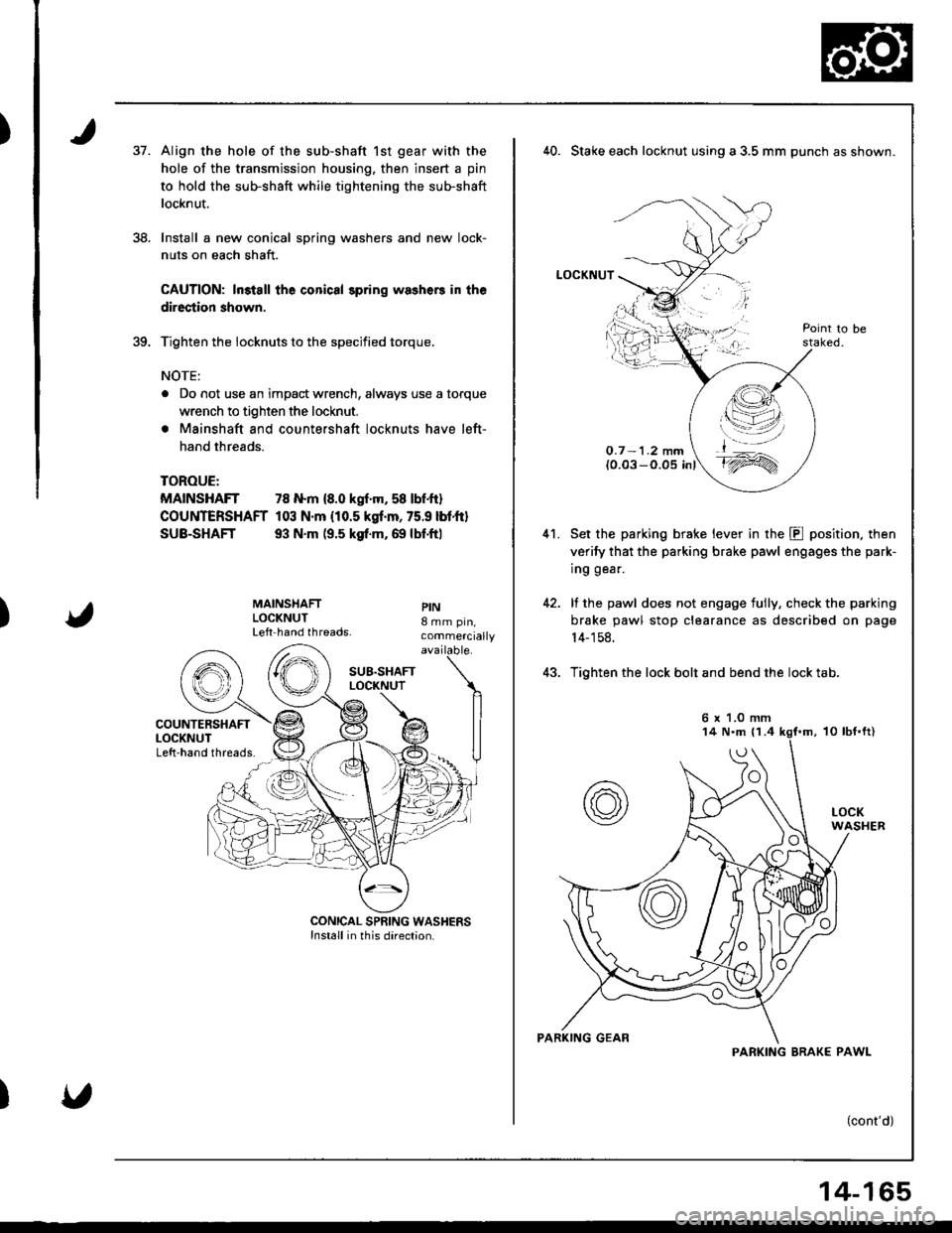
)37.
38.
Align the hole of the sub-shaft 1st gear with the
hole of the transmission housing. then insert a pin
to hold the sub-shaft while tightening the sub-shaft
locknut.
Install a new conical spring washers and new lock-
nuts on each shaft.
CAUTION: ln3tall the conical spring washers in the
direction shown.
Tighten the iocknuts to the specified torque.
NOTE:
a Do not use an impact wrench, always use a torque
wrench to tighten the locknut.
. Mainshaft and countershaft locknuts have left-
hand threads.
TOROUE:
MAINSHAFT 78 N.m {8.0 kgf.m, 58 lbf.ft}
COUNTERSHAFT 103 N.m {10.5 kgf.m, 75.9 lbtft}
SUB-SHAFT 93 N.m (9.5 ksf.m, 69 lbf.ftl
)
MAINSHAFTLOCKNUTLeft hand threads.
PIN8 mm pin,commercially
40. Stake each locknut using a 3,5 mm punch as shown.
LOCKNUT
O.7 -1.2 mm(0.03 -O.05 inl
Set the parking brake lever in the E position. then
verify that the parking brake pawl engages the park-
ing gear.
lf the pawl does not engage tully, check the parking
brake pawl stop clearance as described on page
14- 1 58.
Tighten the lock bolt and bend the lock tab.
(cont'd)
41.
t,\--l--'-,4 l';-.-='/
t_^
t'1ry
6 x 1.0 mm
PARKING BRAK€ PAWL
14-165
Page 582 of 1681
Transmission
Reassembly lcont'd)
41.
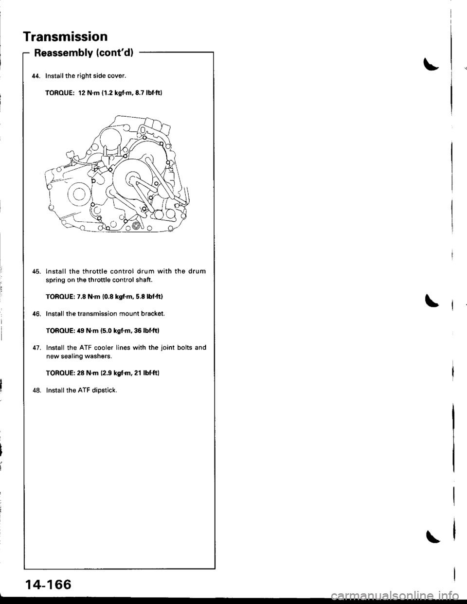
Installthe right side cover.
TOROUE: 12 N.m { 1.2 kgf.m,8.7 lbtft}
lnstall the throttle control drum with the drum
spring on the throttle control shaft.
TOROUE: 7.8 N.m 10.8 kgf.m, 5.8 lbf,ftl
Install the transmission mount bracket.
TOROUE: 49 N.m {5.0 kgf.m,36lbf,ft)
Install the ATF cooler lines with the joint bolts and
new sealing washers.
TOROUE: 28 N.m (2.9 kgf.m, 21 lbf.ft)
Install the ATF dipstick.
\
\
14-166
\
Page 584 of 1681
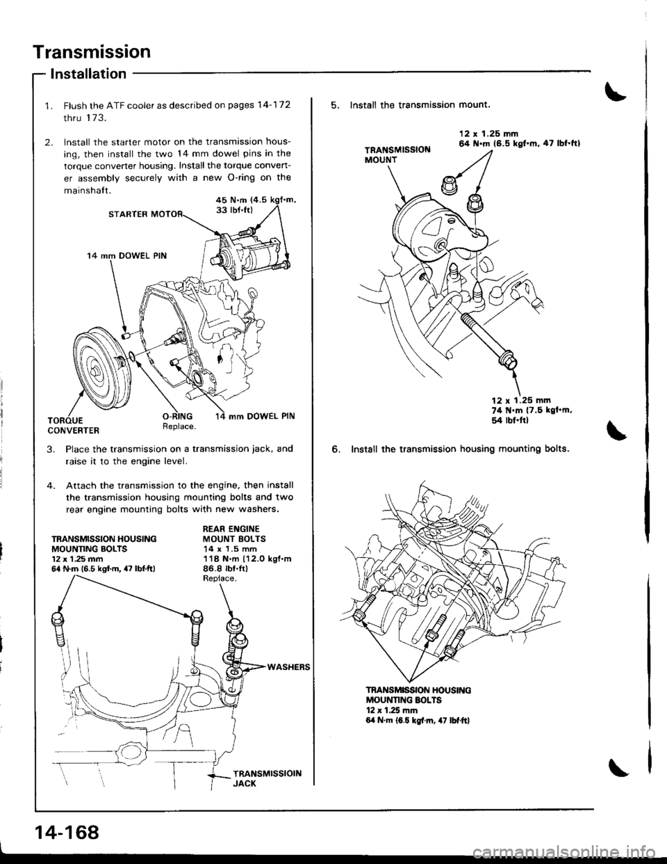
Transmission
lnstallation
Flush the ATF cooler as described on pages 14-172
thru 173.
lnstall the starter motor on the transmission hous-
ing, then install the two 14 mm dowel pins in the
torque convener housing. Install the torque conven-
er assembly securely with a new O-ring on the
mainshalt.45 N.m (4.5
33 lbJ.ft)STARTER
14 mm DOWEL PIN
mm DOWEL PIN
CONVERTERReplace.
3. Place the transmission on a transmission jack, and
raise it to the engine level.
4. Attach the transmission to the engine, then install
the transmission housing mounting bolts and two
rear engine mounting bolts with new washers.
TRANSMISSION HOUSINGMOUNNNG BOLTS12 x 1 ,25 mm64 N.m (6.5 kgf.m, 47 lbf.ftl
REAR ENGINEMOUNT BOLTS14 x 1.5 mm118 N.m 112.0 kgl.m86.8 rb{.tr)
WASHEFS
14-168
5. Install th€ transmission mount.
6. Instsll the transmission
12 x 1.26 mm64 N.m 16.5 kgt.m,47 lbf.ftl
74 t{'m {7.5 kgt'm,
54 rbl.ftl
housing mounting bolts.
MOUNNNG SOLTS12 r 1.25 mm6,t N.m 16.5 kgl.rn, 47 lbf"ftl
TRANSMISSON HOUSING
Page 585 of 1681
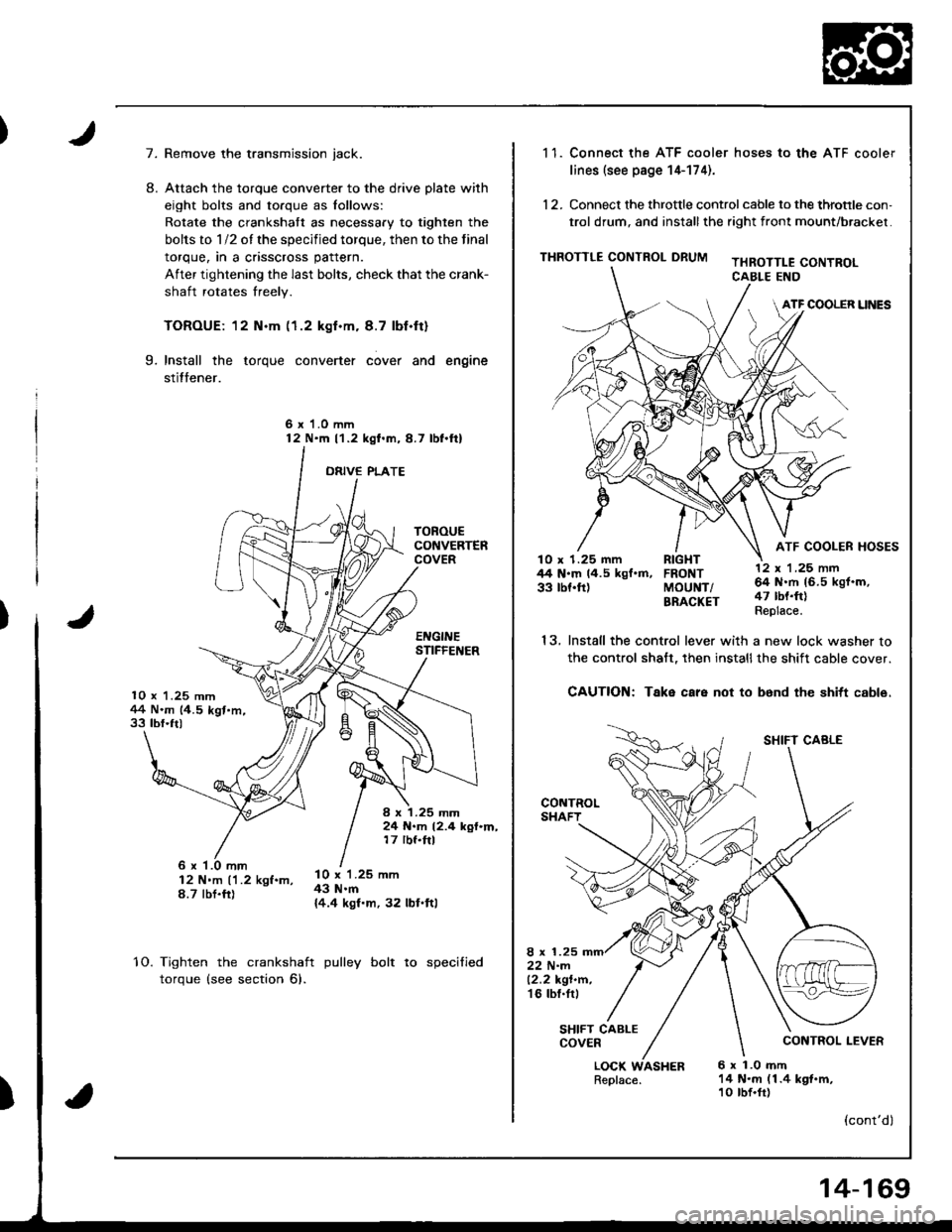
7.
10 x 1.25 mm1+4 N.m (4.5 kgt.m,33 tbf.ft)
TOROUECONVERTERCOVER
EI{GINESTIFFEI{ER
I x 1.25 mm24 N.m 12.4 kgf.m,17 rbf.ftl
8.
Remove the transmission jack.
Attach the torque converter to the drive plate with
eight bolts and torque as lollows:
Rotate the crankshatt as necessary to tighten the
bolts to 1/2 of the specified torque, then to the final
torque, in a crisscross pattern.
After tightening the last bolts, check that the crank-
shaft rotates freely.
TOROUE: 12 N.m (1.2 kgf.m. 8.7 lbf.ft)
Install the torque converter cover and engine
stitfener.
6 x 1.0 mm12 N'm l'1.2 kgl.m,8.7 lbl.ftl
ORIVE PLATE
9.
6 x '1.0 mm12 N'm ('1.2 kgf.m,8.7 tbt.fr)
l0 x 1.25 mm43 N.m{4.4 kgf.m, 32 lbl.ftl
10.Tighten the crankshaft
torque (see section 6).
pulley bolt to specified
)
1 1. Connect the ATF cooler hoses to the ATF cooler
lines (see page 14-174).
12. Connect the throttle control cable to the throtrle con,
trol drum, and installthe right front mount/brackel.
THROTTLE CONTROL DRUMTHROTTLE CONTROLCABLE END
ATF COOLER UNES
ATF COOLER HOSESlO x 1.25 mm RIGHT44 N.m 14.5 kgf.m, FRONT33 tbf.ft) MoUNT/BRACKET
13.
LOCK WASHERReplace.6 x 1.0 mft14 N.m (1.4 kgt.m,10 tbf.fr)
12 x 'l ,25 nn64 N.rh 16.5 kgf.m,47 tbt.ft)Replace.
SHIFT CABLE
CONTROL LEVER
(cont'dl
Install the control lever with a new lock washer to
the control shalt, then installthe shift cable cover.
CAUTION: Take care not to b6nd the shitt cable.
8 x 1.2522 N-m12.2 kgt.n.'t6 tbl.tr,
SHIFT CABLECOVER
14-169
Page 586 of 1681
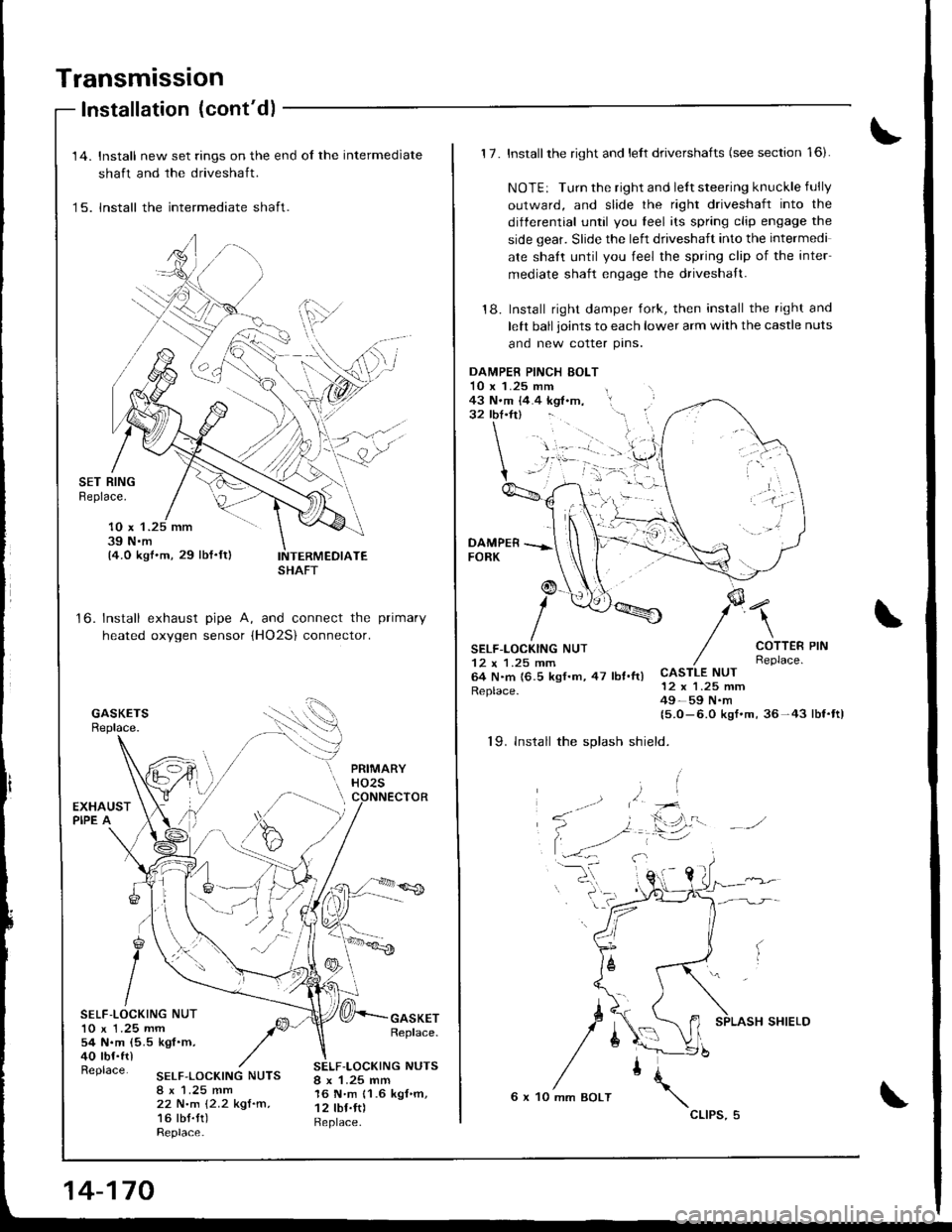
Transmission
Installation (cont'd)
to.
'14. Install new set rings on the end ol the intermediate
shaft and the driveshaft.
'15. lnstall the intermediate shaft.
SET RINGBeplace.
10 x 139 N.m14.0 kgf.m, 29 lbf.ft)
Install exhaust pipe A, and connect the primary
heated oxygen sensor (HO2S) connector.
g
ISELF-LOCKING NUT10 x 1.25 mm54 N.m (5.5 kgf.m,40 tbf.frlReplace.
GASKETReplace.
SELF,LOCKING NUTS8 x 1.25 mm22 N.m {2.2 kgf.m,16 tbt.tt)Replace.
SELF-LOCKING NUTS8 x 1.25 mm16 N'm 11.6 kgf.m,12 tbf.ft)Replace.
SHAFT
14-170
6 x 10 mm BOLT
cllPs,5
1 7. Install the right and lelt drivershafts (see section '16).
NOTE: Turn the right and le{t steering knuckle fully
outward, and slide the right driveshaft into the
differential until you leel its spring clip engage the
side gear. Slide the left driveshaft into the intermedi
ate shaft until you feel the spring clip of the inter
mediate shaft engage the driveshaft.
'18. Install right damper fork, then insrall the right and
lett ball joints to each lower arm with the castle nuts
and new cotter prns.
\
COTTERReplace.CASTLE NUT12 x 1.25 mm49-59 N.m15.0- 6.0 kgf.m,36-43 lbl.tt)
19. lnstall the splash shield.
DAMPEB PINCH EOLT10 x 1.25 mm43 N.m {4.4 kgf .m, l.32 lb{.tr} - '- i
:'g
SELF-LOCKING NUT12 x 1.25 mm64 N.m {6.5 kgf.m,47 lbt.ftlReplace.
PIN
SHIELD
Page 587 of 1681
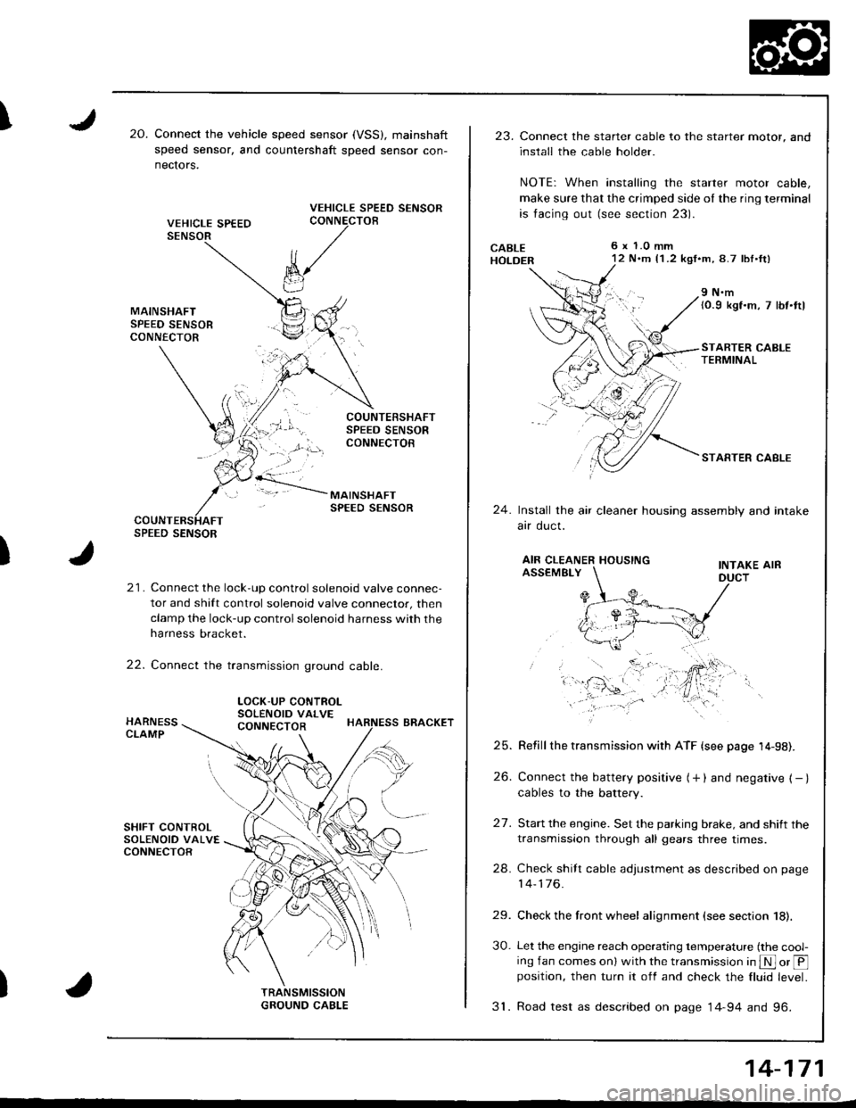
I20.Connect the vehicle speed sensor (VSS), mainshaft
speed sensor, and countershaft sDeed sensor con-
nectors.
VEHICLE SPEED SENSORCONNECTOB
)
k/
t"J
21. Connect the lock-up control solenoid valve connec-
tor and shift control solenoid valve conneclor, then
clamp the lock-up control solenoid harness with the
harness bracket.
22. Connect the transmission ground cable.
SPEED SENSOR
LOCK-UP CONTROLSOLENOID VALVECONNECTOR
23.Connect the starter cable to the starter motor, and
install the cable holder.
NOTE: When installing the starter motor cable,
make sure that the crimped side ol the ring terminal
is facing out (see section 23).
6 x 1.0 mm12 N.m {1 .2 kgf.m, 8.7 lbl.ft)
9 N.m(0.9 kgf.m, 7 lbt.ttl
STARTER CABLETERMINAL
STARTER CABLE
24.Install the air cleaner housing assembly and intake
arr oucl.
AIR CLEANER HOUSINGINTAKE AIRASSEMBLY
27.
Refill the transmission with ATF {see page 14-98).
Connect the battery positive (+ ) and negative { - }cables to the battery.
Start the engine. Set the parking brake, and shift the
transmission through all gears three times.
Check shilt cable adjustment as described on page
14-176.
Check the front wheel alignment (see section 18).
Let the engine reach operating temperature (the cool-ing fan comes onl with the transmission in S or @position, then turn it off and check the fluid level.
31. Road test as described on page 14-94 and 96.
25.
26.
24.
29.
30.
14-171
Page 588 of 1681
Transmission
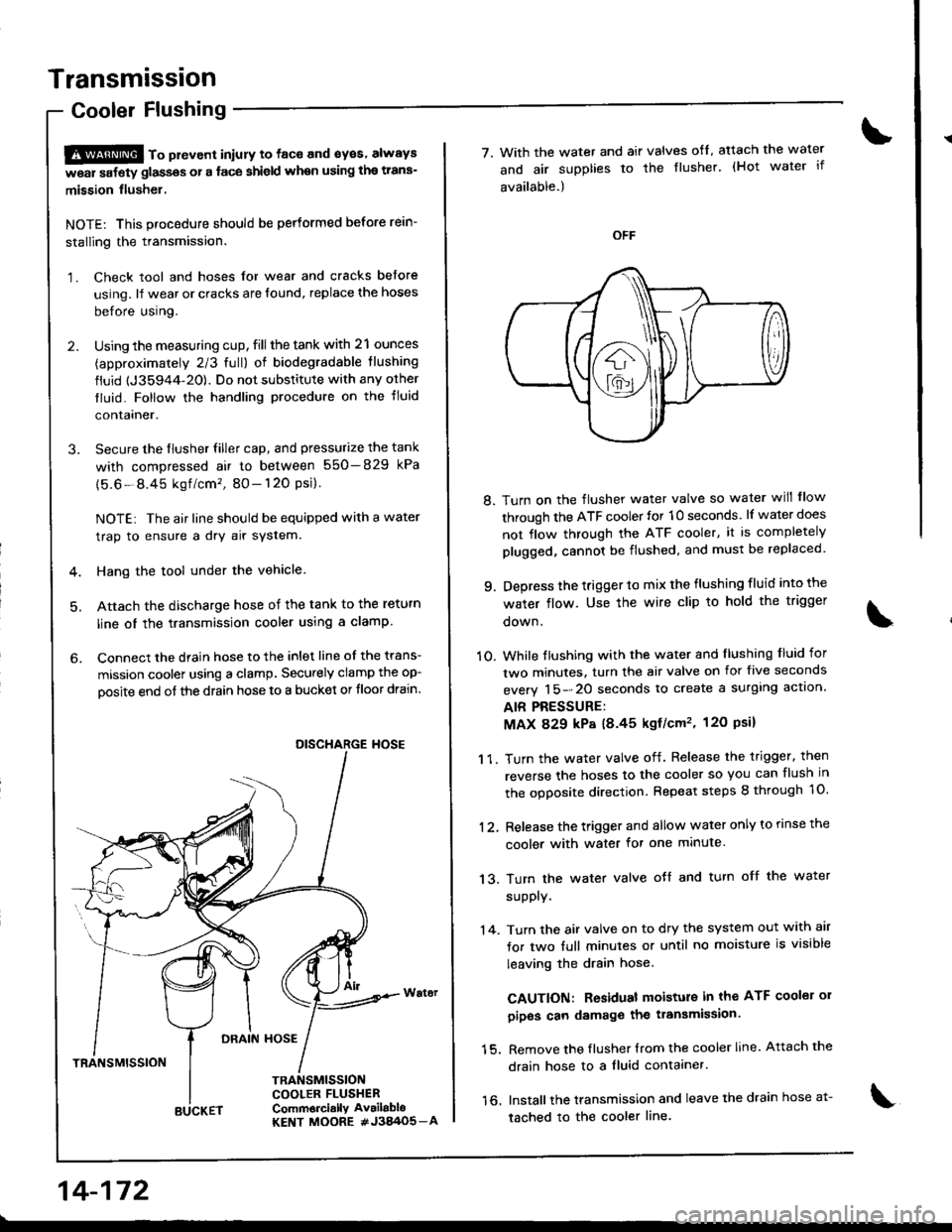
Cooler Flushing
S@ to pttvont iniury to face and syes' always
w6ar safety glassos or a face shield when using the trans-
mission flusher.
NOTE: This procedure should be performed before rein-
stalling the transmission.
1. Check tool and hoses for wear and cracks before
using. lf wear or cracks are found, replace the hoses
before using.
2. Using the measuring cup, fill the tank with 21 ounces
(approximately 2/3 full) of biodegradable tlushing
fluid {J35944-20). Do not substitute with any orher
tluid. Follow the handling procedure on the tluid
contalner.
3. Secure the flusher filler cap, and pressurize the tank
with compressed air to between 550-829 kPa
{5.6-8.45 kgf /cm'�, 80- 120 Psi}.
NOTE: The air line should be equipped with a water
trap to ensure a dry air system.
4. Hang the tool under the vehicle
5. Attach the discharge hose of the tank to the return
line oI the transmission cooler using a clamp
6. Connect the drain hose to the inlet line of the trans-
mission coolel using a clamp. Securely clamp the op-
oosite end of the drain hose to a bucket or tloor drain.
DRAIN HOSE
TRANSMISSION
TRANSMISSIONCOOLER FLUSHERComm6rci.llY Av.ilabloKENT MOORE #J3A/O5_A
DISCHARGE HOSE
14-172
BUCKET
7. With the water and air valves ofl, atach the water
and air supplies to the flusher. (Hot water if
available.)
8. Turn on the flusher water valve so water will flow
through the ATF cooler for 10 seconds. lf water does
not flow through the ATF cooler, it is completely
plugged, cannot be flushed, and must be replaced
9. Depress the trigger to mix the flushing fluid into the
water flow. Use the wire clip to hold the trigger
oown.
1O. While tlushing with the water and llushing f luid for
two minutes. turn the air valve on for five seconds
everv 15-20 seconds to create a surglng actlon.
AIR PRESSURE:
MAX 829 kP8 18.45 kgf/cm'�, 120 Psil
1 1. Turn the water valve off. Release the trigger. then
reverse the hoses to the cooler so you can flush in
the ooDosite direction. Repeat steps 8 through 1O.
12, Release the trigger and allow water only to rinse the
cooler with water for one minute.
13. Turn the water valve oJf and turn off the water
supply.
'14. Turn the air valve on to dry the system out with air
for two full minutes or until no moisture is visible
leaving the drain hose.
CAUTION: Residual moisture in the ATF coolei 01
pipos can damage the transmission.
15. Remove the flusher {rom the cooler line. Attach the
drain hose to a fluid contaaner.
16. Installthe transmission and leave the drain hose a1-
tached to the cooler line.