differential HONDA INTEGRA 1998 4.G Owner's Guide
[x] Cancel search | Manufacturer: HONDA, Model Year: 1998, Model line: INTEGRA, Model: HONDA INTEGRA 1998 4.GPages: 1681, PDF Size: 54.22 MB
Page 623 of 1681
Limited Slip Differential (B18C5 engine)
Tapered Roller Bearing Preload Adiustment (cont'd)
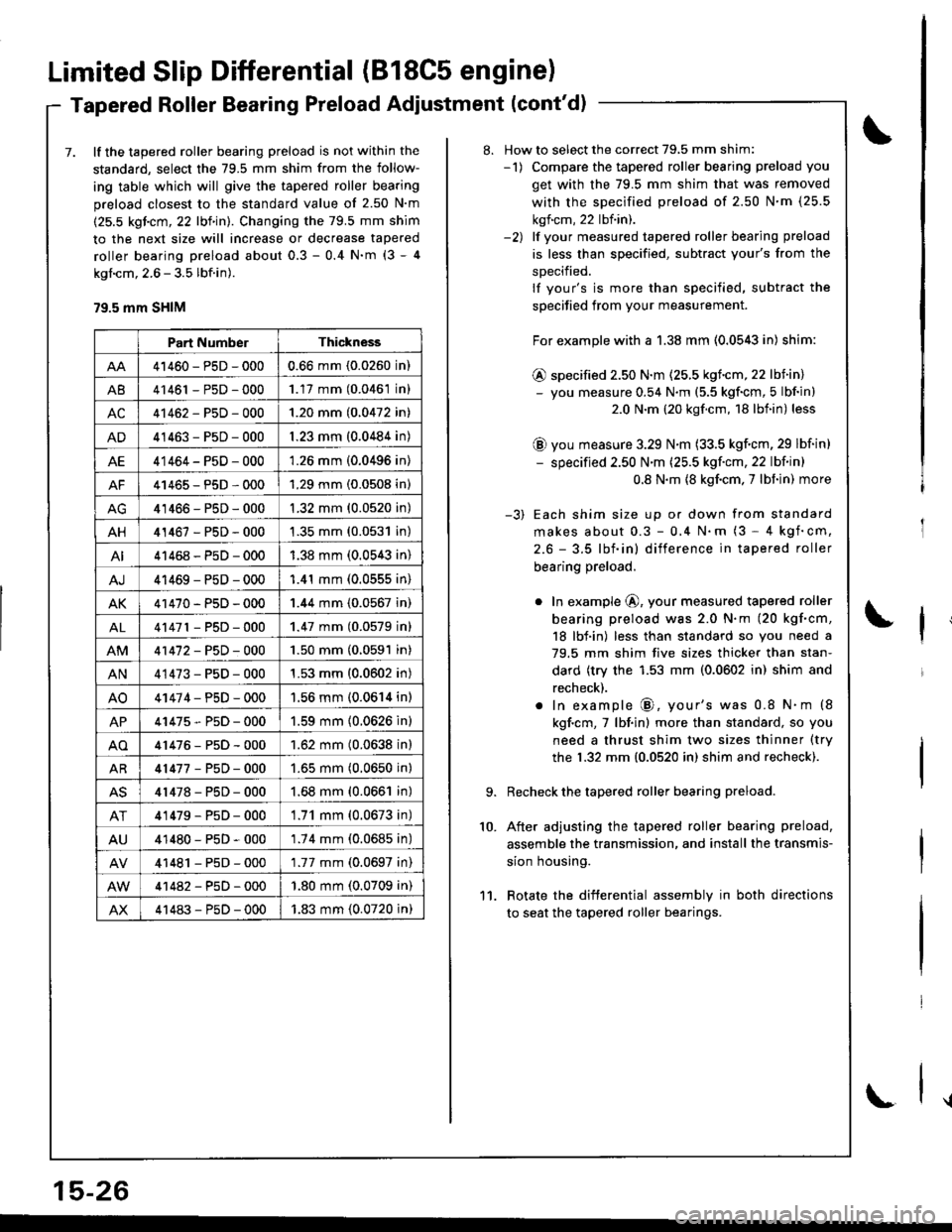
7. lf the tapered roller bearing preload is not within the
standard, select the 79.5 mm shim from the follow-
ing table which will give the tapered roller bearing
preload closest to the standard value of 2.50 N'm
(25.5 kgicm, 22 lbf in). Changing the 79.5 mm shim
to the next size will increase or decrease tapered
roller bearing preload about 0.3 - 0.4 N'm (3 - 4
kgl.cm, 2.6 - 3.5 lbf.in).
79.5 mm SHIM
Part NumberThickness
41460-PsD-0000.66 mm (0.0260 in)
A841461 - P5D - 0001.17 mm (0.0461 in)
AC41462-P5D-0001.20 mm (0.0472 in)
AD41463-P5D-0001.23 mm (0.0484 in)
AE41464-P5D-0001.26 mm (0.0496 in)
AF41465-P5D-0001.29 mm (0.0508 in)
41466-PsD-0001.32 mm (0.0520 in)
AH41467-PsD-0001.35 mm (0.0531 in)
AI41468-P5D-0001.38 mm (0.0543 in)
AJ41469-PsD-0001.41 mm (0.0555 in)
AK41470-PsD-0001.44 mm (0.0567 in)
AL41471 - PsD - 0001.47 mm (0.0579 inl
41472-P5D-0001.50 mm (0.0591 in)
AN41473-P5D-0001.53 mm (0.0602 in)
AO41474-PsD-0001.56 mm (0.0614 in)
AP41475-P5D-0001.59 mm (0.0626 in)
AO41476-P5D-0001.62 mm (0.0638 in)
AR41477-P5D-0001.65 mm (0.0650 in)
AS41478-PsD-0001.68 mm (0.0661 in)
AT41479-P5D-0001.71 mm (0.0673 in)
AU41480-PsD-0001.74 mm (0.0685 in)
41481 - PsD - 0001.77 mm (0.0697 in)
41482-P5D-000'1.80 mm (0.0709 in)
AX41483-P5D-0001.83 mm (0.0720 in)
15-26
\
8. How to select the correct 79,5 mm shim:-1) Compare the tapered roller bearing preload you
get with the 79.5 mm shim that was removed
with the sDecified preload of 2.50 N'm (25.5
kgf.cm, 22 lbf.in).-2) lf vour measured tapered roller bearing preload
is less than specified, subtract your's from the
sDecified.
lf your's is more than specified, subtract the
specified from your measurement.
For example with a 1.38 mm (0.0543 in) shim:
@ specified 2.50 N.m (25.5 kgf.cm,22 lbiin)- you measure 0.54 N.m (5.5 kgf'cm, 5 lbf in)
2.0 N.m (20 kgf.cm, 18 lbf.in) less
@ you measure 3.29 N.m (33.5 kgf.cm, 29 lbf in)
- specified 2.50 N'm (25.5 kgf'cm, 22 lbf in)
0.8 N.m {8 kgf.cm. 7 lbf in) more
-3) Each shim size up or down from standard
makes about 0.3 - 0,4 N.m (3 - 4 kgf'cm,
2.6 - 3.5 lbf.in) difference in tapered roller
bearing preload.
o In example @, your measured tapered roller
bearing preload was 2.0 N.m (20 kgf.cm,
18 lbf.in) less than standard so you need a
79.5 mm shim five sizes thicker than stan-
dard (try the 1.53 mm (0.0602 in) shim and
recheck).
. In example @, your's was 0.8 N.m (8
kgf.cm,7 lbf.in) more than standard, so you
need a thrust shim two sizes thinner (try
the 1.32 mm {0.0520 in) shim and recheck).
Recheck the tapered roller bearing preload.
After adjusting the tapered roller bearing preload,
assemble the transmission, and install the transmis-
sion housing.
Rotate the difterential assembly in both directions
to seat the tapered roller bearings.
10.
11.
Page 624 of 1681
Differential (Automatic Transmission)
Speciaf Tools ........... ..........15-2A
Differential (Automatic Transmissionl
lllustrated Index .......... .. 15-29
Backlash Inspection ...... 15-30
Bearing Rep|acement ......................... I 5-30
Differential Carrier Replacement ...... l5-31
Oil SealRemoval ........... 15-32
Oil Seal Installation/
Side G|earance ................................. 1 5-32
Page 626 of 1681
Differential (Automatic Transmission)
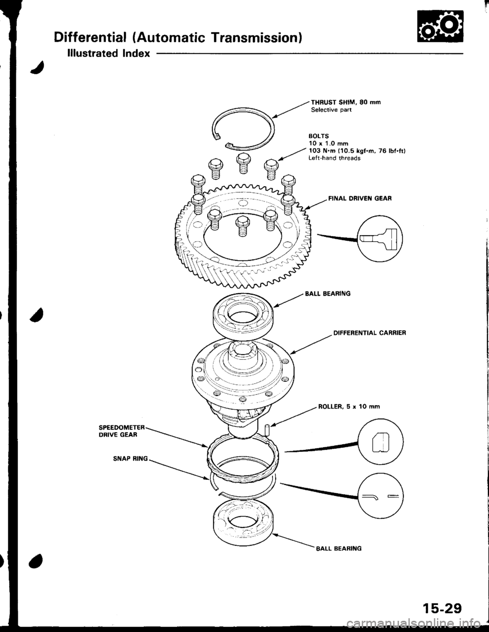
lllustrated Index
FINAL DRIVEI{ GEAR
BALL BEARIiIG
--tot"'
ENTIAL caRRlER
ROLLER,5xlOmm
BALL BEARING
15-29
Page 627 of 1681
Differential (Automatic Transmissionl
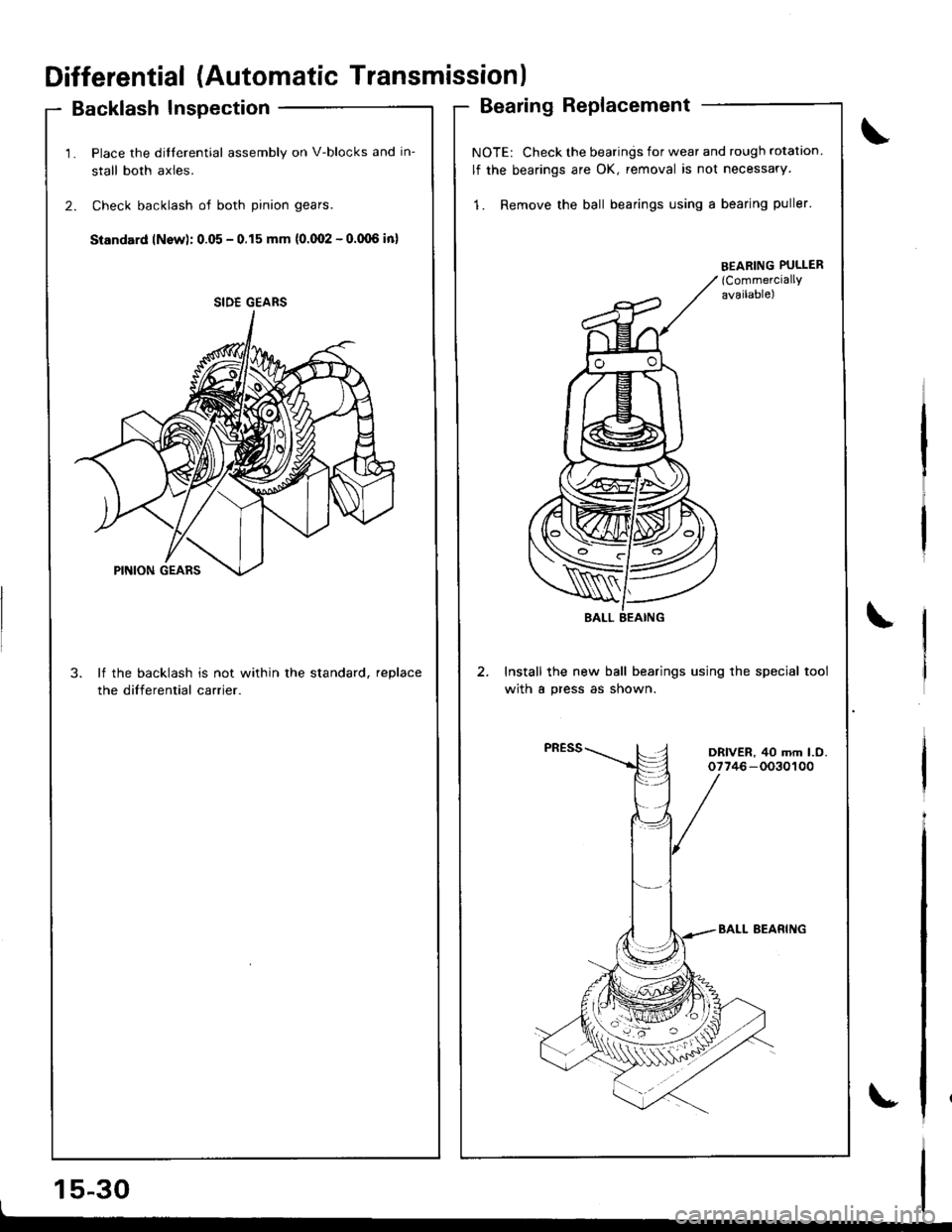
Backlash Inspection
1. Place the dilferential assembly on V-blocks and in-
stall both axles.
2. Check backlash of both pinion gears.
Standard lNsw): 0.05 - 0.15 mm {0.(Xt2 - o.(Xl6 in)
3. lf the backlash is not within the standard, reDlace
the differential carrier.
15-30I
Bearing Replacement
NOTE: Check the bearings for wear and rough rotation
lf the bearings are OK, removal is not necessary.
1. Remove the ball bearings using a bearing puller'
Install the new ball bearings using the special tool
with a press as shown.
SIDE GEARS
EEABING PULLER(CommerciallY
available)
\
DRIVER, 40 mm l.O.07746-0030100
Page 628 of 1681
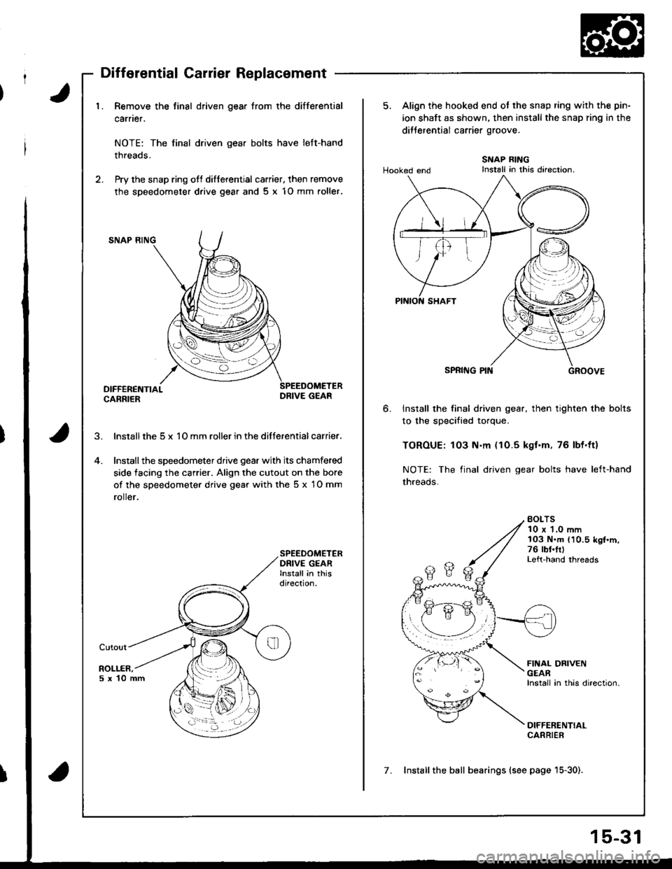
J1. Remove the final driven gear from the differential
carner.
NOTE: The final driven gear bolts have left-hand
threads.
2. Pry the snap ring ofl differential carrier, then remove
the speedometer d.ive gear and 5 x 1O mm roller.
SNAP RING
DIFFERENTIALCARRIERDRIVE GEAR
lnstall the 5 x 1O mm roller in the differential carrier.
Installthe speedometer drive gear with its chamfered
side facing the carrier. Align the cutout on the bore
of the speedometer drive gear with the 5 x 1O mm
ro er.
SPEEDOMETERDRIVE GEARInstall in thisdirection.
Cutout
ROLLER,5x10mm
5. Align the hooked end ot the snap ring with the pin-
ion shaft as shown. then install the snap ring in the
dilJerential carrier groove.
Hooked endSNAP RINGInstall in this direction.
6.Install the final driven gear, then tighten the bolts
to the specified torque.
TOROUE: 103 N.m (10.5 kgt.m, 76 lbl.ttl
NOTE: The final driven gear bolts have left-hand
threads.
BOLTS10 x 1.0 mm103 N.m (10.5 kgf.m,76 rbt.frlLeft-hand threads
FINAL DRIVENGEARInstall in this direction.
DIFFERENTIALCARRIER
7. Installthe ball bearings (see page 15-30).
Page 629 of 1681
Differential (Automatic Transmissionl
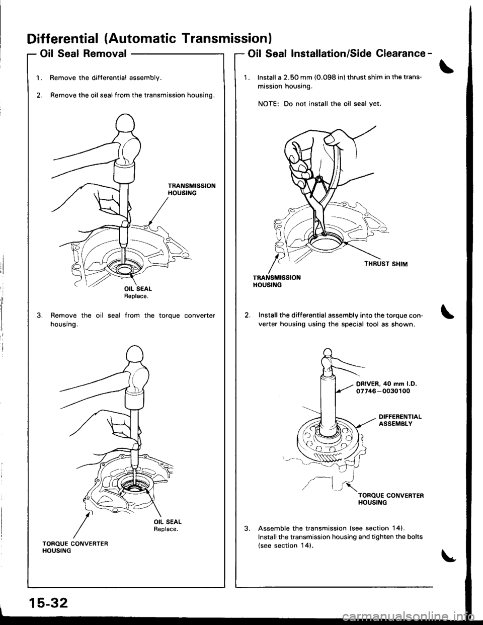
Oil Seal Removal
Remove the differential assembly.
Remove the oil sealfrom the transmission housing.
Remove the oil seal from the torque converter
housing.
Oil Seal Installation/Side Clearance-
1 . Install a 2.50 mm {O.O98 in} thrust shim in the trans-
mission housing.
NOTE: Do not install the oil seal yet.
TRANSMISSIONHOUStf{G
Install the differential assembly into the torque con-
verter housing using the special tool as shown.
DRIVER, 40 mm l.D.07746-0030100
DIFFERENTIALASSEMBLY
/--1TOROUE CONVERTERHOUSING
Assemble the transmission lsee section 141.
Installthe transmission housing and tighten the bolts(see section 14).TOROUE CONVERTERHOUSING
15-32
OIL SEALReplace.
Page 630 of 1681
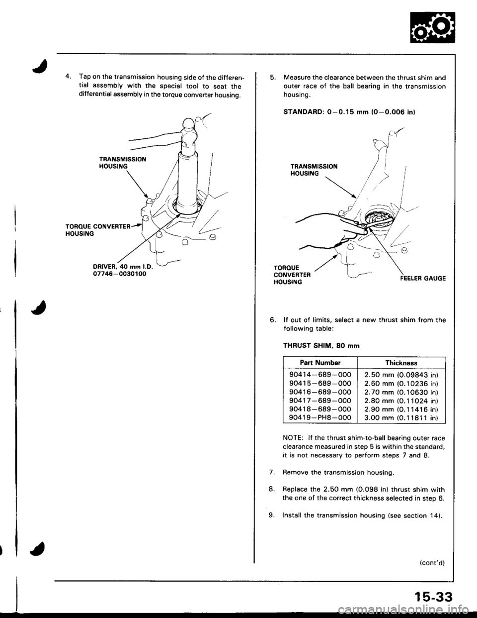
4.Tap on the transmission housing side of the ditferen-tial assembly with the special tool to seat thedifferential assembly in the torque convener housing.
o.
Measure the clearanc; between the thrust shim and
outer race of the ball bearing in the transmission
nousrng.
STANDARD: O-0.15 mm (O-O.O06 in)
It out of limits. select a new thrust shim from the
tollowing table:
THRUST SHIM, 80 mm
NOTE: Il the thrust shim-to-ball bearing outer race
clearance measured in step 5 is within the standard,
it is not necessary to perform steps 7 and 8.
Remove the transmission housing.
Replace the 2.50 mm {0.098 in) thrust shim with
the one of the correct thickness selected in step 6.
Install the transmission housing (see sectjon 14).
7.
L
Part NumberThickness
904r4-689-000
90415-689-000
90416-689*000
90417-689-OOO
90418-689-O00
90419-PH8-000
2.50 mm (0.09843 in
2.60 mm (0.10236 in
2.70 mm (O.10630 in
2.80 mm {O. 1 1O24 in
2.90 mm {O.1 141 6 in
3.OO mm (O. l '181 1 in
9.
Page 631 of 1681
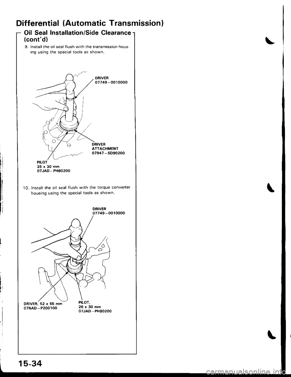
Differential (Automatic Transmission)
Oil Seal Installation/Side Clearance
(cont'd)
9. lnstall the oil seal llush with the transmission hous-
ing using the special tools as shown.
ATTACHMENTo7947 -SD90200
10.
PILOT26x30mmoTJAO-PHA0200
Install the oil seal llush with the torque converter
housing using the special tools as shown.
15-34
Page 635 of 1681
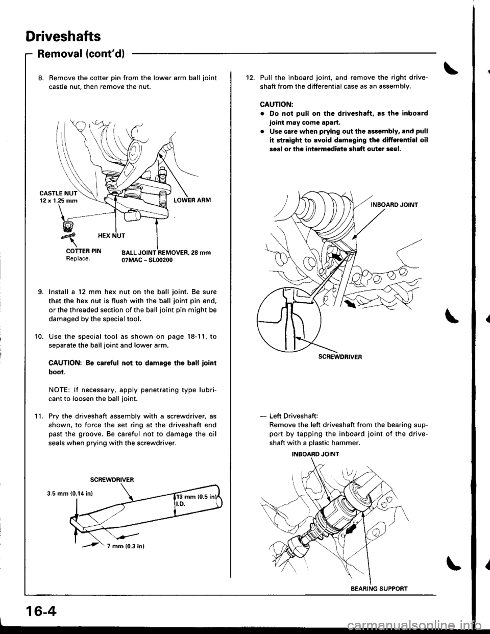
Driveshafts
Removal (cont'dl
11.
8. Bemove the cotter pin from the lower arm ball joint
castle nut. then remove the nut.
urJr rEr rrN BALL JOINT REMOVER,2S mmReplace. OTMAC - SLOO2OO
Install a 12 mm hex nut on the ball joint. Be sure
that the hex nut is flush with the ball joint pin end.
or the threaded section of the ball joint pin might be
damaged by the special tool.
Use the special tool as shown on page 18-11, to
separate the ball ioint and lower arm.
CAUTION: Be careful not to damage th6 ball ioint
boot.
NOTE: lf necessary, apply penetrating type lubri-
cant to loosen the ball joint.
Pry the driveshaft assembly with a screwdriver, as
shown, to force the set ring at the driveshaft end
past the groove. Be careful not to damage the oil
seals when prying with the screwdriver.
12. Pull the inboard joint, and remove the right drive-
shaft from the differential case as an assemblv.
CAUTION:
. Do not pull on the driveshaft. as lhe inbosrd
ioint may come 8p8rt.
. Use care when prying out the assembly, snd pull
it straight to avoid damaging the differential oil
seal or the intermsdiats rhaft outcr 3e81.
- Left Driveshaft:
Remove the left driveshaft from the bearing sup-
port by tapping the inboard joint of the drive-
shaft with a Dlastic hammer.
SCREWDRIVER
BEARING SUPPORT
16-4
Page 646 of 1681
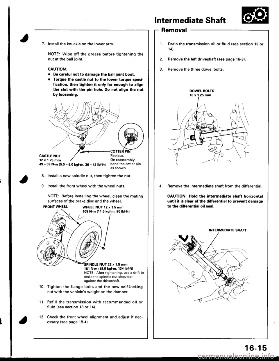
Intermediate Shaft
Removal
Drain the transmission oil or fluid {see section 13 or
14t.
Remove the left driveshaft (see page 16-3).
Bemove the three dowel bolts.
Remove the intermediate sh8ft from the differential.
CAUTION: Hold the intermediate shaft horizontal
until it is clear ot th6 difforantirl to prevont damage
to thc ditf€rential oil seal.
7. Install the knuckle on the lower arm.
NOTE: Wipe off the grease before tightening the
nut at the ball joint.
CAUTION:
. Be careful not to damago the ballioint boot.
. Torque the castle nut to tho low€r torque speci-
tication, then tighten it only lar onough to align
th6 slot whh tho pin hols. Do not align the nut
by loosening.
,.<__coTTEF PtNCASTLE NUT12 x 1.25 mm49 - 59 N.m {5.0 - 5.0 kgf.m, 36 - t3 lbl.ft)
Beplace.On reassembly,bend the cotter pin
8. Install a new spindle nut, then tighten the nut.
9. Installthe front wheel with the wheel nuts.
NOTE: Before installing the wheel, clean the mating
surfaces of the brake disc and the wheel.
FRONT WHEELWH€EL NUT 12 x 1.5 mm108 N.m (11.0 kgt m,80lbf ft)
10.
NUT 22 x '1.5 mm181 N m 118.5 kgl.m, 134lbtftlNOTE: After tightening, use a drift tostake the spindle nut shoulderagainst the driveshatt.
Tighten the flange bolts and the new self-locking
nut with the vehicle's weight on the damper.
Refill the transmission with recommended oil or
fluid (see section 13 or 14).
11.
12. Check the front wheel alignment and adjust if nec-
essary (see page 18-4).
INTERMCOIATE SHAFT
16-15