differential HONDA INTEGRA 1998 4.G Owner's Manual
[x] Cancel search | Manufacturer: HONDA, Model Year: 1998, Model line: INTEGRA, Model: HONDA INTEGRA 1998 4.GPages: 1681, PDF Size: 54.22 MB
Page 609 of 1681
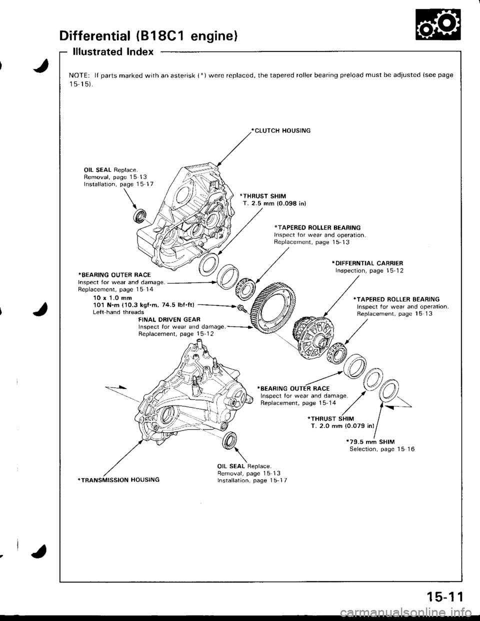
Differential (B18C1 engine)
lllustrated Index
J
J
NOTE: lI parts marked with an asterisk {*)were replaced, the tapered roller bearing preload must be adjusted (see page
15 15).
*CLUTCH HOUSING
OIL SEAL Replace.Removal, page 15 13Installation, page 15 17
*THRUST SHIMT. 2.5 mm {0.098 in)
*TAPERED ROLLER BEARINGlnsDect for wear and ooeration.Replacement, page 1 5-13
*BEARING OUTER RACEInspect for wear and damage.Replacemenl, page 15 14
10 x 1.0 mm
*DIFFERNTIAL CARRIERInspection, page 15-12
101 N.m {'10.3 kgf.m, 74.5 lbf.It)Le{t hand threads
*TAPERED ROLLER BEARINGInspect tor wear and operation.Replacement, page 15 13FINAL DRIVEN GEARInspect tor wear and damage. -----------r'
Repfacement. page 15-1 2
}BEARING OUTER RACE
*79.5 mm SHIMSelection, page 15 16
*TRANSMISSION HOUSING
OIL SEAL Replace.Removal, page 15-13Installation, page 1 5-17
.la
15-1 1
Page 610 of 1681
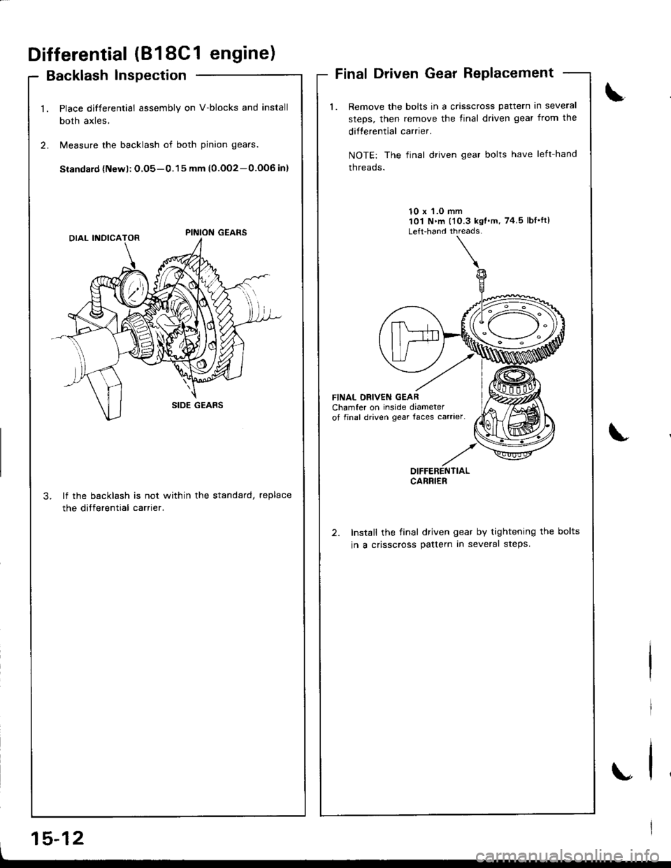
Differential (818C1 engine)
Backlash lnspection
Place differential assembly on V-blocks and install
both axles,
Measure the backlash of both pinion gears.
Siandard {Newl: O.O5-0.15 mm (0.OO2-0.OOG in}
lf the backlash is not within the standard, replace
the differential carrier.
Final Driven Gear Replacement
Remove the bolts in a crisscross pattern in several
steps, then remove the tinal driven gear from the
difterential carrier.
NOTE: The final driven gear bolts have left-hand
threads.
10 x 'l.O mm101 N.m l'10.3 kgt'm, 74 5lbf'ft)
Left-hand threads-
FINAL DBIVEN GEARChamfer on inside diameterof final driven gear Iaces carrier
Install the final driven gear by tightening the bolts
in a crisscross pattern in several steps.
\
.,
OIFFERENTIALCARRIER
I
15-12
Page 612 of 1681
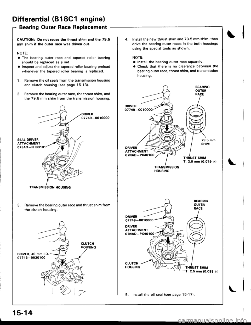
CAUTION: Do not reuse the thruEt shim and th€ 79.5
mm shim if the outer race was driven out.
NOTE:
a The bearing outer race and tapered roller bearing
should be reDlaced as a set.
a Inspect and adjust the tapered roller bearing preload
whenever the tapered roller bearing is replaced.
1 . Remove the oil seals from the transmission housing
and clutch housing (see page 15-13).
2. Remove the bearing outer race, the thrust shim, and
the 79.5 mm shim from the transmission housino.
DRIVER07749-0010000
SEAL ORIVERATTACHMENT07JAD -PH80101
DRIVER, 40 mm LD.07746 -O030100
3.
TRANSMISSION HOUSING
Remove the bearing outer race and thrust shim from
the clutch housing.
CLUTCHHOUSING
ORIVERATTACHMENT07NAD-PX40100
ATTACHMENTo7f{AD-PX40lOO
DRIVERo7749 -0010000
TRANSMISSIONHOUSING
BEARINGOUTERRACE
79.5 mmSHIM
BEARINGOUTERRACE
THRUST SHIMT. 2.5 mm 10.098 inl
lnstall the new thrust shim and 79.5 mm shim. then
drive the bearing outer races in the both housings
using the special tools as shown.
NOTE:
a Install the bearing outer race squarely.
a Check that there is no clearance between the
bearing outer race. thrust shim, and transmission
housing.
ORIVEB
5. Install the oil seal (see page 15-17).
Differential (818C1 engine)
Bearing Outer Race Replacement
15-14
\l
\
\
Page 614 of 1681
Differential
Ted Roll
(B18C1
er Bearinr
engine)
Preload Adjustment (cont'd)aperelng
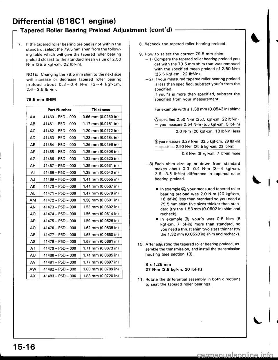
7. lf the tapered roller bearing preload is not within the
standard, select the 79.5 mm shim from the follow-
ing table which will give the tapered roller bearing
preload closest to the standard mean value o{ 2.50
N.m (25.5 kgt.cm, 22 lbf.in).
NOTE: Changing the 79.5 mm shim to the next size
will increase or decrease tapered roller bearing
preload about O.3-0.4 N.m (3-4 kgl.cm,
2.6 - 3.5 lbf.in).
79.5 mm SHIM
Part NumberThickness
41460-PsD-0000.66 mm (0.0260 in)
AB41461 - P5D - 0001.17 mm (0.0461 in)
AC41462-PsD-0001.20 mm (0.0472 in)
AD41463-P5D-0001.23 mm (0.0484 in)
AE41464-PsD-000'1.26 mm (0.0496 in)
AF41465-PsD-0001.29 mm (0.0508 in)
AG41466-PsD-0001.32 mm (0.0520 in)
AH41467-PsD-0001.35 mm 10.0531 in)
AI41468-PsD-0001.38 mm (0.0543 in)
41469-P5D-0001.41 mm (0.0555 inl
AK41470-PsD-0001.44 mm (0.0567 in)
AL41471 - PsD - 000'1.47 mm {0.0579 in}
41472-P5D-0001.50 mm (0.0591 in)
AN41473-PsD-0001.53 mm {0.0602 in}
AO41474-P50-0001.56 mm (0.0614 in)
AP41475-PsD-0001.59 mm (0.0626 in)
AO41476-P5D-000'1.62 mm {0.0638 in}
AR41477-P5D-0001.65 mm (0.0650 in)
41478-P5D-0001.68 mm (0.0661 in)
41479-P50-0001.71 mm (0.0673 in)
AU41480-PsD-0001.74 mm (0.0685 in)
41481 - PsD - 000'1.77 mm (0.0697 in)
41482-PsD-000'1.80 mm (0.0709 in)
AX41483-P5D-0001.83 mm (0.0720 in)
8. Recheck the tapered roller bearing preload.
9. How to select the correct 79.5 mm shim:
1) Compare the tapered roller bearing preload you
get with the 79.5 mm shim that was removed
with the soecified mean Dreload of 2.50 N'm
(25.5 kgf .cm, 22 lbf.in).- 2l ll vour measured tapered roller bearing preload
is less than specified, subtract your's from the
specitied.
lf vour's is more than specitied, subtract the
soecified from vour measurement.
For example with a 1.38 mm {0.0543 in) shim:
@ specified 2.50 N.m (25.5 kgf.cm, 22 lbl.in)- you measure 0.54 N.m (5.5 kg{.cm, 5lbl.in}
2.0 N.m (20 kgf.cm, 18lbf.in) less
@you measure 3.29 N.m (33.5 kgI.cm, 29 lbt.in)- specified 2.50 N.m (25.5 kgf.cm, 22 lbf.in)
0.8 N.m (8 kgf.cm,7lbf.in) more
-3) Each shim size up or down from standard
makes about O.3-0.4 N.nt (3-4 kgf.cm,
2.6-3.5 lbl.in) difterence in tapered roller
bearing preload.
a In example @, your measured tapered roller
bearing preload was 2.O N.m (2O kgt.cm,
18 lbf in) less than standard so you need a
79.5 mm shim live sizes thicker than stan-
dard {try the 1.53 mm (O.0602 in) shim and
recheck).
a ln example @ your's was 0.8 N.m {8
kgf.cm,7lbf.in) more than standard. so
you need a thrust shim two sizes thinner (try
the 1 .32 mm (O.O52O in) shim and recheck).
1O. After adjusting the tapered roller bearing preload, as-
semble the transmission, and installthe lransmission
housing (see section 13).
8 x 1.25 mm
27 N,m (2.8 kgt'm, 20 lbf.ft)
11. Rotate the difterential assembly in both directions
to seat the tapered roller bearings.
1 5-16
\
Page 616 of 1681
Differential (818C5 engine)
SpecialTools .......... ........... 15-20
Limited Slip Differential
Description ..................... 15-21
OperationalGheck ......... 15-23
Rotating Torque Gheck .15-23
lffustrated Index .......... ..15-24
Tapered Roller Bearing Preload
Adjustment ................. 15-25
Page 618 of 1681
Limited Slip Differential (818C5 engine)
Description
t
f1t
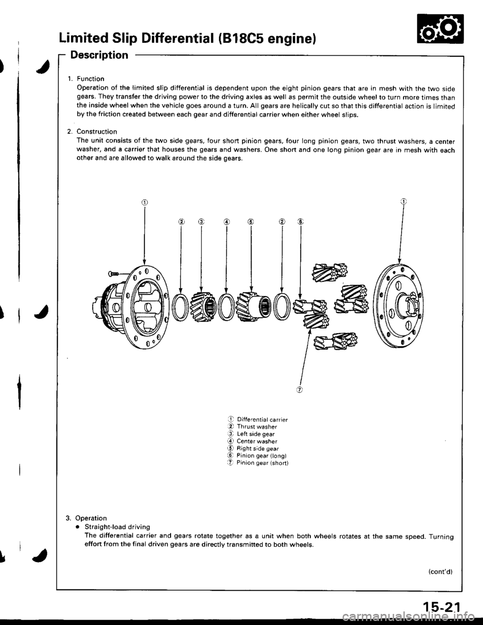
1. Function
Operation of the limited slip differential is dependent upon the eight pinion gears that are in mesh with the two sidegears. They transfer the driving power to the driving axles as well as permjt the outside wheel to turn more times thanthe inside wheel when the vehicle goes around a turn. All gears are helically cut so that this differential action is limitedby the friction created between each gear and differential carrier when either wheel slips.
2. Construction
The unit consists of the two side gears, four short pinion gears, four long pinion gears, two thrust washers, a centerwasher, and a carrier that houses the gears and washers. One shon and one long pinion gear are in mesh with eachother and are allowed to walk around the side oears.
w
I
I
I
+
@
a,
e Differentiatcarrier
a Thrust washer
@ Left side gear
O Center washerg Right side gear
O Pinion gear ong)O Pinion gea r (short)
Ooeration
. Straight-load driving
The differential carrier and gears rotate together as a unit when both wheels rotates at the same speed. Turningeffon from the final driven gears are directly transmitted to both wheets.
(cont'd)
l,'a
15-21
Page 619 of 1681
Limited Slip Differential (B18C5 engine)
Description (cont'd)
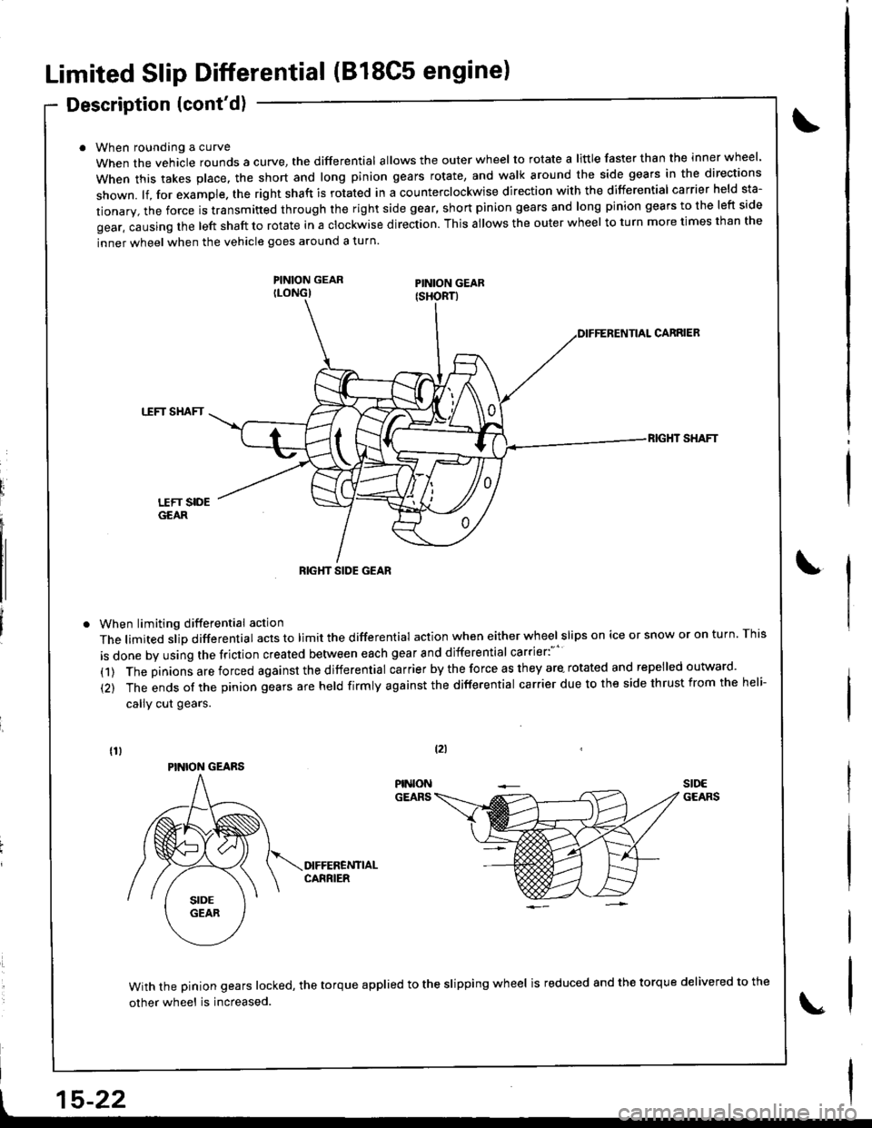
When roundang a curve
When the vehacle rounds a curye, tne differential allows the outer wheel to rotate a little faster than the inner wheel.
when this takes p|ace. the short and |ong pinion gears rotate, and wa|k around the side gears in the directions
shown. lf, for example. the right shaft is rotated in a counterclockwise direction with the differential carrier held sta-
tionary, the force is transmitted through the right side gear, short pinion gears and long pinion gears to the left side
gear, causing the left shaft to rotate in a clockwise direction. This allows the outer wheel to turn more times than the
inner wheel when the vehicle goes around a turn.
PINION GEARILONG)
When limiting differential action
The limited slip differential acts to limit the differential action when either wheel slips on ice or snow or on turn. This
is done by using the friction created between each gear and differential carrier:"''
(1) The pinions are forced against the differential carrier by the force as they are- rotated and repelled outward.
(2) The ends of the pinion gears are held firmly against the differential carrier due to the side thrust from the heli-
callY cut gears.
CARRIEB
TTFT SHAFT
RIG}IT SHAFT
With the pinion gears locked, the torque applied to the slipping wheel is reduced 8nd the torque delivered to the
other wheel is increased.
tzl
t15-22
RIGHT SIDE GEAR
PINION GEARS
Page 620 of 1681
Operational Check
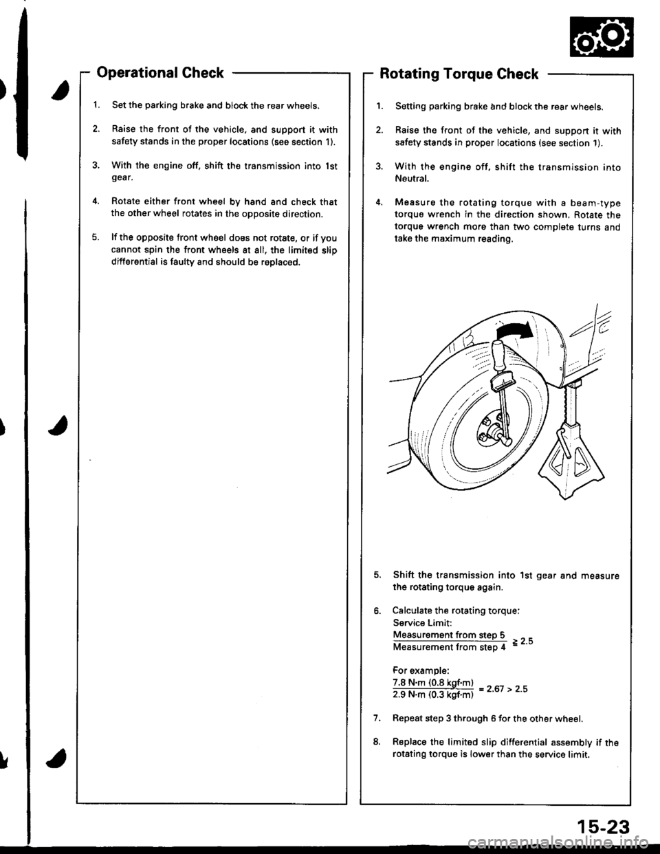
Set the parking brake and block the rear wheels.
Raise the front of the vehicle, and support it with
safety stands in the proper locations (see section 1).
With the engine off, shift the transmission into lstgear,
Rotate either front wheel bv hand and check that
the other wheel rotates in the opposite direction.
lf the opposite tront wheel does not rotste, or if voucannot spin the front wheels at all, the limited slip
differential is faulty and should be roplaced.
Rotating Torque Check
Setting parking brake and block the rear wheels.
Raise the front of the vehicle, and support it with
safety stands in proper locations (see section 1).
With the engine off, shift the transmission into
Neutral.
Measure the rotating torque with a beam-type
torquo wrench in the direction shown, Rotate the
torque wrench morg than two complete turns and
take the maximum reading.
Shift the transmission into 1st gear and measure
the rotating torque again.
Calculate the rotating torque:
Service Limit:
Measur€ment from steD 5
Measurementfrom step 4 =--
For example:
7.8 N.m (0.8 kgf.m)
zg N"ll (03 kgf'ntl = z'ot > z''
Repeat step 3 through 6 for the other wheel.
Replace the limited slip differential assembly if the
rotsting lorque is lower than the service limit.
!
15-23
Page 621 of 1681
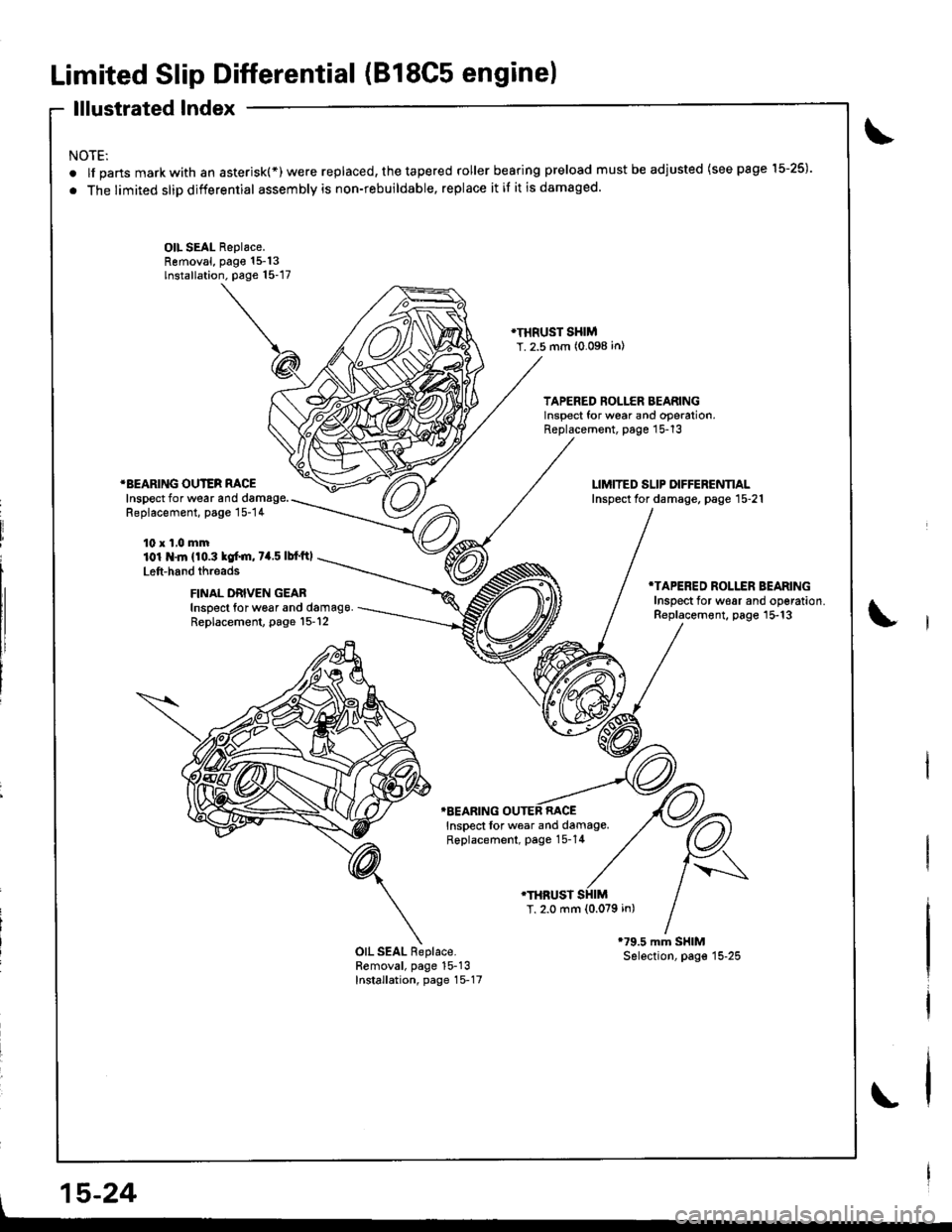
Limited Slip Differential (B18C5 engine)
lllustrated Index
NOTE:
.lfpartsmarkwithanasterisk(*)werereplaced,thetaperedrollerbearingpreloadmustbeadjusted(seepagel5-25).
. The limited slip differential assembly is non-rebuildable, replace it if it is damaged.
OIL SEAL Replace.Removal, page 15-13lnstallation. page 15-17
}I}IRUST SHIMT. 2.5 mm (0.098 in)
TAPERED ROLLER BEARINGlnsoect for wear and ooeration,Replacement, page 15-13
*BEARING OUTER RACEInspect for wear and damage.Replacement, page 15-14
10 x 1,0 mm101 .ln {10.3 kof.m, 7a.5 lbf'ftl
Left-hand threads
FINAL DRIVEN GEABInspect for w6ar and damag9.Replacement, page l5-12
*TAPERED ROLLER BEARINGInsDect for w€ar and oo€ration.Replacement, page 15-13
TBEARING OUTEB RACEInspect lor wear and damage.Replacement, page 15-14
.THRUST
T, 2.0 mm {0.079 in)
OIL SEAL Replace.Removal, page 15-13Installation, page 15-17
l,
, 15-24
Page 622 of 1681
J
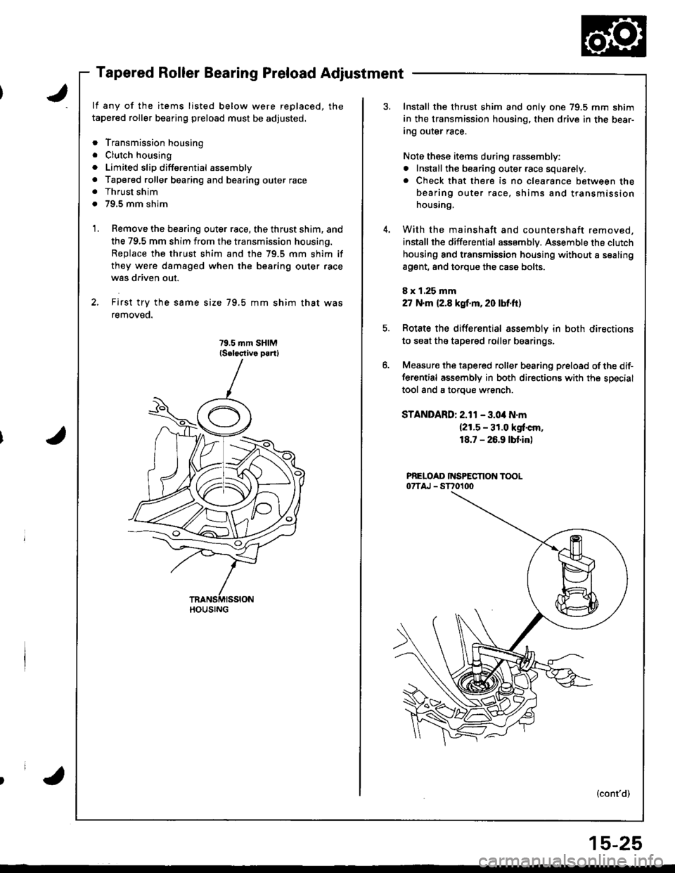
Tapered Roller Bearing Preload Adjustment
lf any of the items listed below were replaced, the
tapered roller bearing preload must be adjusted,
. Transmission housing
. Clutch housing
. Limited slip diffsrential assembly
. Tapored roller bearing and bearing outer race. Thrust shim
. 79,5 mm shim
Remove the bearing outer race, the thrust shim, and
the 79,5 mm shim from the transmission housing.
Replace the thrust shim and the 79.5 mm shim if
they were dsmaged when the bearing outer race
was driven out.
First try the same size 79.5 mm shim that was
removeo.
HOUSING
Install the thrust shim and only one 79.5 mm shim
in the transmission housing, then drive in the bear-
Ing our€r race.
Noto these items during rassembly:
. Install the bearing outer race squarely.. Check that there is no clearance between the
bearing outer race, shims and transmission
housing,
With the mainshatt and countershaft removed,
installthe differential assemblv. Assemble the clutch
housing and transmission housing without a sealing
a9ent, and torque the case bolts.
8 x 1.25 mm
27 N.m (2.8 kgf.m, 20 lM.ft)
Rotate the differential assemblv in both directions
to seat the tapered roller bearings.
Measur€ the tapered roller bearing preload of the dif-
ferential assembly in both directions with the special
tool and a toroue wrench.
STANDARD: 2.11 - 3.04 N.m(2!.5 - 31.0 kgt'cm,
18.7 - 26.9 lbf.in)
PNELOAD INSPECTION TOOL07TAJ - ST701dt
(cont'd)
15-25