engine oil HONDA INTEGRA 1998 4.G Repair Manual
[x] Cancel search | Manufacturer: HONDA, Model Year: 1998, Model line: INTEGRA, Model: HONDA INTEGRA 1998 4.GPages: 1681, PDF Size: 54.22 MB
Page 607 of 1681
Differential (818C1 engine)
Special Tools ........ ........ 15-10
Differential
lllustrated Index......... . 15-11
Backfash Inspection .,.. 15-12
Finaf Driven Gear Replacement ...... 15-12
Tapered Roller Bearing Replacement. 15-13
Oil Seal Removal ........ 15-13
Bearing Outer Race Replacement ... 15-14
Tapered Roller Bearing Preload
Adjustment ............. 15-15
Oif Seaf Installation ..... 15-17
Page 609 of 1681
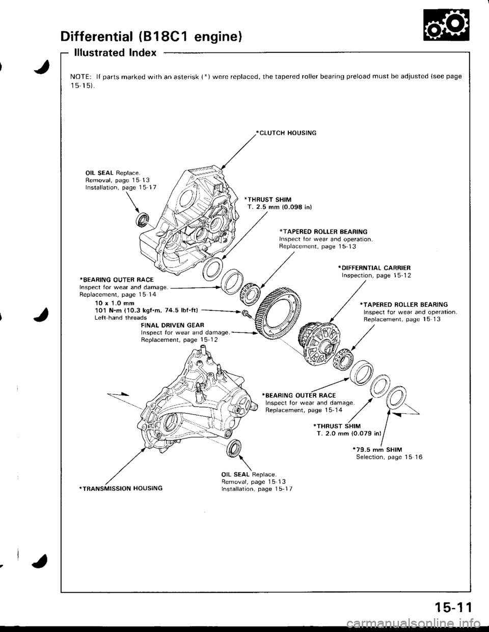
Differential (B18C1 engine)
lllustrated Index
J
J
NOTE: lI parts marked with an asterisk {*)were replaced, the tapered roller bearing preload must be adjusted (see page
15 15).
*CLUTCH HOUSING
OIL SEAL Replace.Removal, page 15 13Installation, page 15 17
*THRUST SHIMT. 2.5 mm {0.098 in)
*TAPERED ROLLER BEARINGlnsDect for wear and ooeration.Replacement, page 1 5-13
*BEARING OUTER RACEInspect for wear and damage.Replacemenl, page 15 14
10 x 1.0 mm
*DIFFERNTIAL CARRIERInspection, page 15-12
101 N.m {'10.3 kgf.m, 74.5 lbf.It)Le{t hand threads
*TAPERED ROLLER BEARINGInspect tor wear and operation.Replacement, page 15 13FINAL DRIVEN GEARInspect tor wear and damage. -----------r'
Repfacement. page 15-1 2
}BEARING OUTER RACE
*79.5 mm SHIMSelection, page 15 16
*TRANSMISSION HOUSING
OIL SEAL Replace.Removal, page 15-13Installation, page 1 5-17
.la
15-1 1
Page 612 of 1681
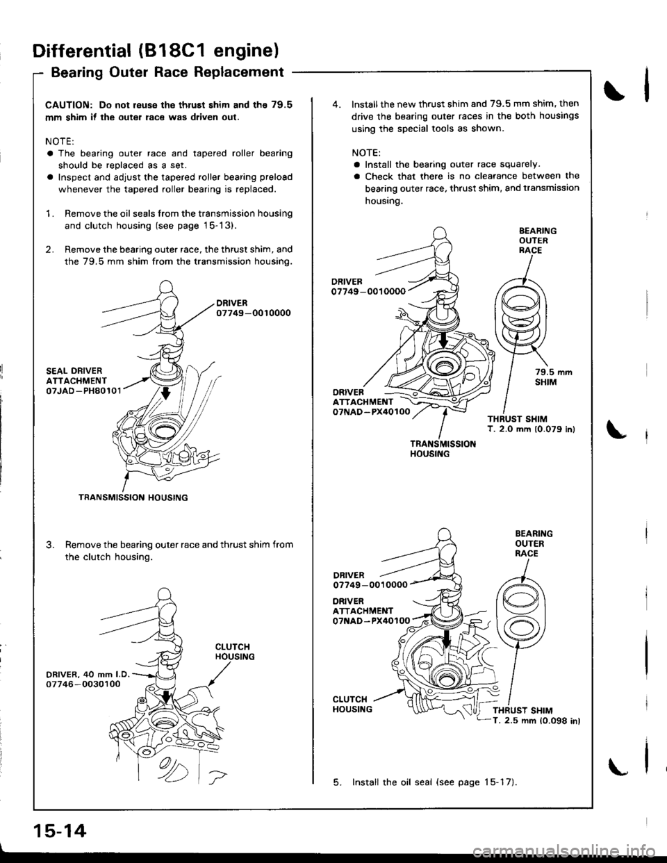
CAUTION: Do not reuse the thruEt shim and th€ 79.5
mm shim if the outer race was driven out.
NOTE:
a The bearing outer race and tapered roller bearing
should be reDlaced as a set.
a Inspect and adjust the tapered roller bearing preload
whenever the tapered roller bearing is replaced.
1 . Remove the oil seals from the transmission housing
and clutch housing (see page 15-13).
2. Remove the bearing outer race, the thrust shim, and
the 79.5 mm shim from the transmission housino.
DRIVER07749-0010000
SEAL ORIVERATTACHMENT07JAD -PH80101
DRIVER, 40 mm LD.07746 -O030100
3.
TRANSMISSION HOUSING
Remove the bearing outer race and thrust shim from
the clutch housing.
CLUTCHHOUSING
ORIVERATTACHMENT07NAD-PX40100
ATTACHMENTo7f{AD-PX40lOO
DRIVERo7749 -0010000
TRANSMISSIONHOUSING
BEARINGOUTERRACE
79.5 mmSHIM
BEARINGOUTERRACE
THRUST SHIMT. 2.5 mm 10.098 inl
lnstall the new thrust shim and 79.5 mm shim. then
drive the bearing outer races in the both housings
using the special tools as shown.
NOTE:
a Install the bearing outer race squarely.
a Check that there is no clearance between the
bearing outer race. thrust shim, and transmission
housing.
ORIVEB
5. Install the oil seal (see page 15-17).
Differential (818C1 engine)
Bearing Outer Race Replacement
15-14
\l
\
\
Page 621 of 1681
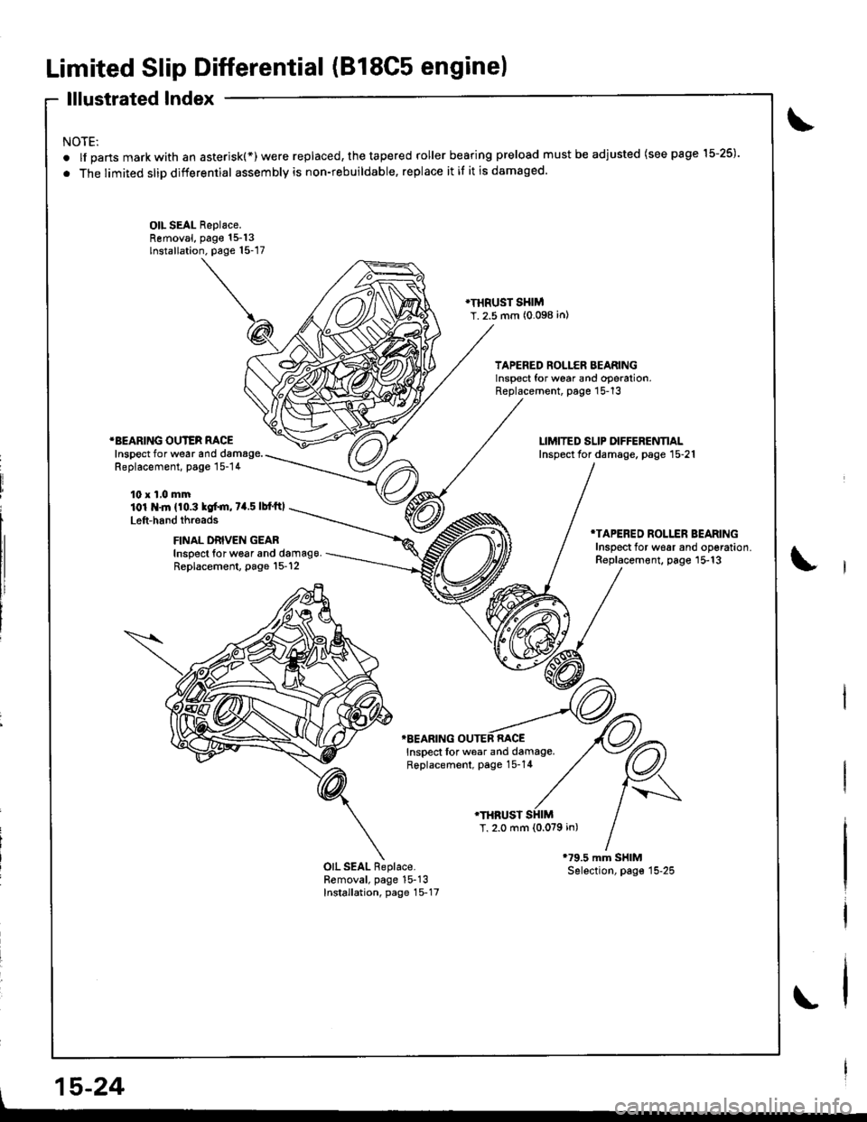
Limited Slip Differential (B18C5 engine)
lllustrated Index
NOTE:
.lfpartsmarkwithanasterisk(*)werereplaced,thetaperedrollerbearingpreloadmustbeadjusted(seepagel5-25).
. The limited slip differential assembly is non-rebuildable, replace it if it is damaged.
OIL SEAL Replace.Removal, page 15-13lnstallation. page 15-17
}I}IRUST SHIMT. 2.5 mm (0.098 in)
TAPERED ROLLER BEARINGlnsoect for wear and ooeration,Replacement, page 15-13
*BEARING OUTER RACEInspect for wear and damage.Replacement, page 15-14
10 x 1,0 mm101 .ln {10.3 kof.m, 7a.5 lbf'ftl
Left-hand threads
FINAL DRIVEN GEABInspect for w6ar and damag9.Replacement, page l5-12
*TAPERED ROLLER BEARINGInsDect for w€ar and oo€ration.Replacement, page 15-13
TBEARING OUTEB RACEInspect lor wear and damage.Replacement, page 15-14
.THRUST
T, 2.0 mm {0.079 in)
OIL SEAL Replace.Removal, page 15-13Installation, page 15-17
l,
, 15-24
Page 662 of 1681
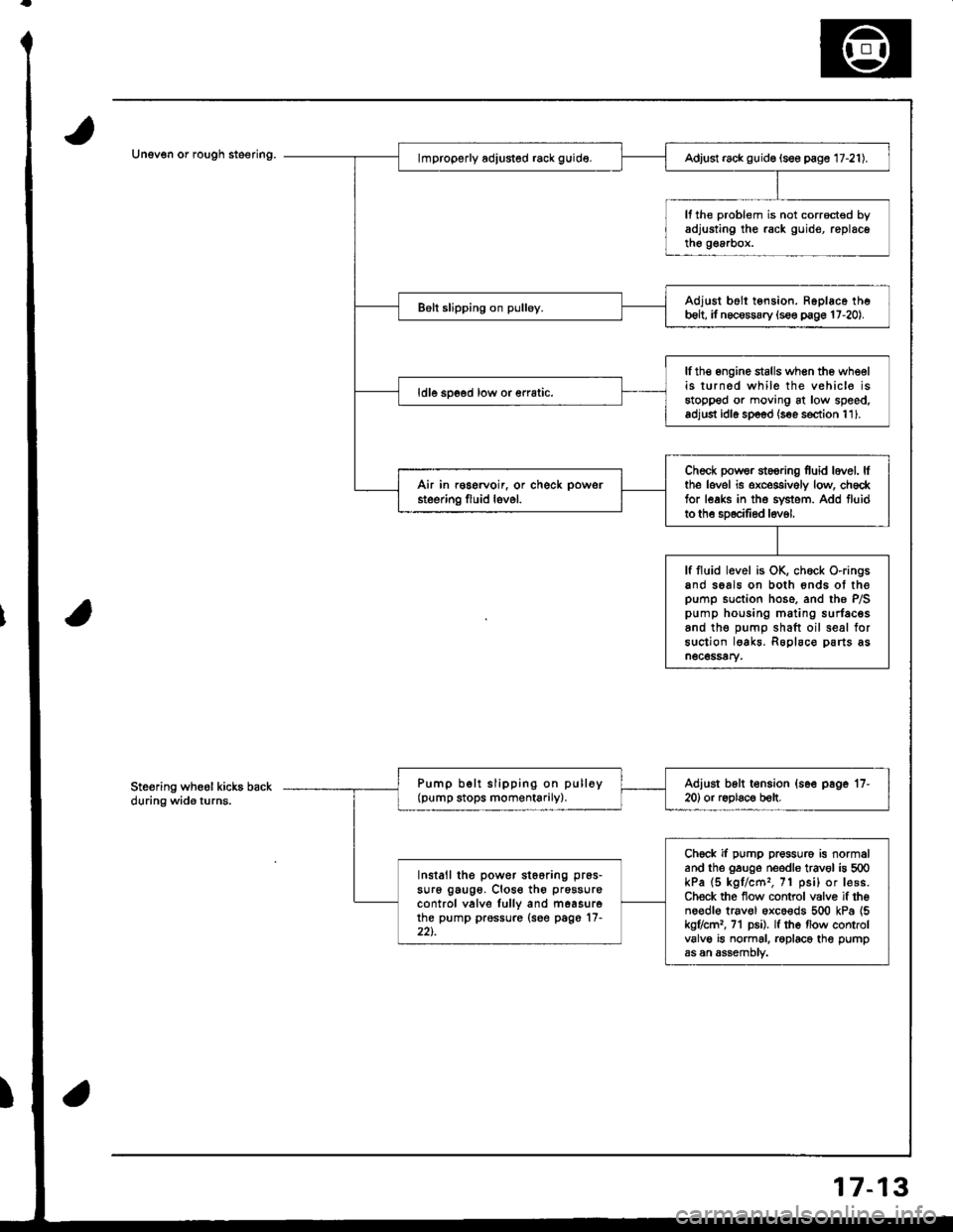
Unev€n or rough steering.Adjust rack guid€ (see page 17-21).
It the problem is not corrocted byadjusting the rack guid€, replacethe g€a.box.
Adjust b6ll tension. Ropl6ce theb6lt, it necossary {s€e p€ge 17-20).
lfth€ engine stalls when the wheelis turned while the vehic16 isstopped or moving at low speed.adjust idl6 sp6od (s€e s€ction 111.
ldle spoed low or €rratic.
Check powsr st6oring fuid lovel. lfthe lovel is exceggively low, ch6cktor leaks in the svstem. Add fluidto the sD6cilied l6v6l,
Air in r€gervoir, or check powsr
steering fluid lovel.
lf fluid level is OK, chock O-ringsand seals on both 6nds ot thepump suction hose. and the P/Spump housing mating surfacesand tho oumo shaft oil seal forsuction lgakr. Roplaco parts asn6c6ssary.
Pump b€lt slipping on pulloy(pump stops momentarily).Adiust b6lt t€nsion {s6e page '17-
20) or r6olac€ b€lt.
Chock if pump pressure is normaland the gauge needle trav€l is 500kPa (5 kgl/cm'�, 71 psi) or lesB.Ch€ck the flow control valvo if theno€dl€ trav€l oxco€ds 500 kPa {5kg7cml, 71 p6i). lf the flow controlvalve is normal. roplace the pumpas an assemDtv.
Install the power st66ring pr6s-
su16 gaug6. Close th6 prossure
control valve lully and m6asurethe pump prossure (see page'17-22t.
Ste€ring wheol kicks backduring wide turns.
7-13
Page 670 of 1681
Rack Guide AdjustmentFluid Replacement
Check the reservoir at regular intervals, and add fluid as
neceSsary.
CAUTION: Use only Genuine Honda Powel Ste€ring
Fluid-V. Using other fluids such as ATF or othor manu-
laclurer's power ste€ring fluid will damag€ the systom.
SYSTEM CAPACIW:
B18Gl ongine:
1.06lit€r (1.12 US. qt,0.93 lmp.qt)
Excopt 8l8Cl ongino:
1.0 lher (r.06 US. qt.0.88 imp.qtl
at disa$ombly
RESERVOIR CAPACITY:
0.,0 liter {0.42 US. qt, 0.35 lmp.qt}
LEVEL LINE
LEVEL LINE
Raise the reservoir and disconnect the return hose
that goes to the oil cooler.
Connect a hose of suitable diameter to the discon-
nected return hose and put the hose end in a suit-
able container.
CAUTION: Take care not to spill thq fluid on lhe
body and parts. Wipe off any spilled fluid al onc€.
Start the engine. let it run at idle, and turn the steer-
ing wheel from lock-to-lock several times. When
fluid stops running out of the hose, shut off the
engine. Discard the fluid.
2.
RETURN HOSE{From the oilcooler)
4. Reinstallthe return hose on the reservoir.
5. Fill the reservoir to the uDDer level line.
6. Start the engine and run it at fast idle, then turn the
steering from lock-to-lock several times to bleed air
from the system,
7. Recheck the fluid level and add some it necessary.
CAUTION: Do not lill the reservoir boyond thc
upper level line.
J.
4.
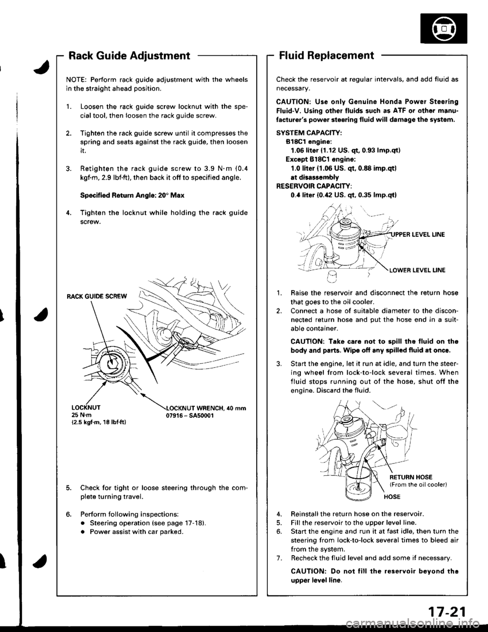
NOTE: Perform rack guide adjustment with the wheels
in the straight ahead position.
1. Loosen the rack guide screw locknut with the spe-
cialtool, then loosen the rack guide screw.
Tighten the rack guide screw until it compresses the
spring and seats against the rack guide, then loosen
it.
Retighten ihe rack guide screw to 3.9 N.m (0.4
kgf.m, 2.9 lbi.ft), then back it ofl to specified angle.
Speciliad Roturn Anglo: 20' Max
Tighten th€ locknut while holding the rack guide
screw.
RACK GUIDE SCREW
25Nm{2.5 kgf.m, 18 lbf ft)
LOCKNUT WRENCH. ilo mm079't 6 - SA50001
E
6.
Check for tight or loose steering through the com-
plete turning travel.
Perform following inspections:
. Steering operation (see page 17-18).
a Power assist with car parked.
I
Page 1049 of 1681
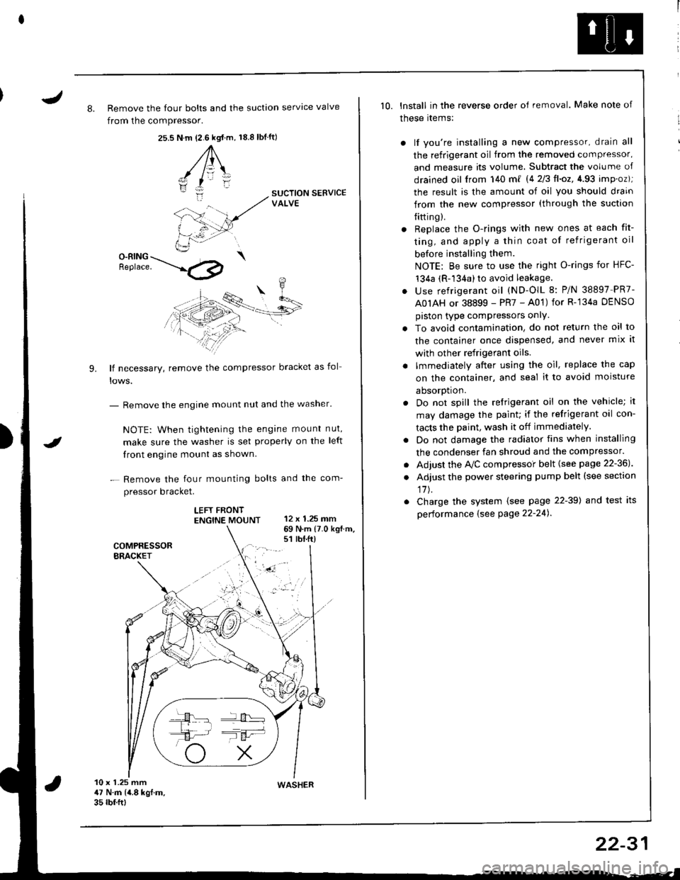
J8. Remove the four bolts and the suction servtce valve
from the compressor.
25.s18.8 tbf.ft)N.m {2.6 kgt.m,
A\
-/ l=\'zI
i:-
9.
SUCTION SERVICEVALVE
O-RING \Benrace. --'.l4p
lf necessary, remove the compressor bracket as fol
- Remove the engine mount nut and the washer'
NOTE: When tightening the engane mount nut,
make sure the washer is set properly on the left
front engine mount as shown.
- Remove the four mounting bolts and the com-
pressor bracket.
LEFT FRONTENGTNE MOUNT 12 x 1.25 mm
I
69 N.m {7.0 kg{.m.s1 rbt.ft)
10 x 1.25 mm47 N.m (4.8 kgf.m.35 rbf.ftt
10. lnstall in the reverse order of removal. Make note of
these rtems:
) lf you're installing a new compressor, drain all
the refrigerant oil from the removed compressor,
and measure its volume, Subtract the volume of
drained oil from 140 m{ 14 2/3ll.oz,4.93 imp.oz);
the result is the amount of oil you should drain
from the new compressor (through the suction
{itting).
r Replace the O-rings with new ones at each fit-
ting, and apply a thin coat of refrigerant oil
before installing them.
NOTE: Be sure to use the right O-rings for HFC-'t34a (R-134a) to avoid leakage.
. use refrigerant oil (ND-OlL 8: P/N 38897 PR7-
A0IAH or 38899 - PR7 - A01) for R-'134a DENSO
piston type compressors onlY.
. To avoid contamination, do not return the oil to
the container once dispensed, and never mix it
with other refrigerant oils.
. lmmediately after using the oil, replace the cap
on the container, and seal it to avoid moisture
aDsorDt|on.
. Do not spill the refrigerant oil on the vehicle; it
may damage the paint; if the refrigerant oil con-
tacts the Daint, wash it off immediately.
. Do not damage the radiator fins when installing
the condenser fan shroud and the compressor.
. Adjust the Ay'C compressoi belt {see page 22-36J
. Adjust the power steering pump belt (see section
17J.
. Charge the system (see page 22-39) and test its
performance {see Page 22-24).
WASHER
22-31
Page 1070 of 1681
Connector ldentification and Wire Harness Routing
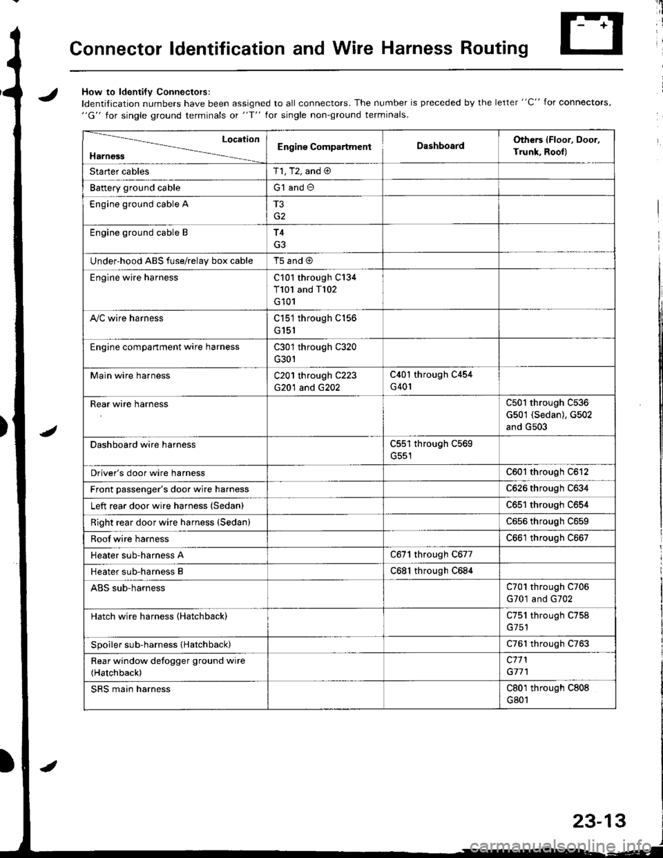
JHow to ldenti{v Connectors:
ldentification numbers have been assigned to all connectors. The number is preceded by the letter "C" for connectors,"G" for single ground terminals ot "f" lor single non-ground terminals.
/
Location
HarnossEngine CompartmentDashboardOthers (Floor, Door,
Trunk. Rooll
Starter cablesT1, T2, and @
Battery ground cableG1 and O
Engine ground cable A
G2
Engine ground cable BT4
G3
Under-hood ABS fuse/relav box cableT5 and @
Engine wire harnessC101 through C134
T101 and T102
G101
A,/C wire harnessC151 through C156
G151
Engine compartment wire harnessC301 through C320
G301
Main wire harnessC201 through C223
G20'l and G202
C40l through C454
G401
Rear wire harnessC501 through C536
G501 (Sedan), G502
and G503
Dashboard wire harnessC551 through C569
G551
Driver's door wire harnessC601 through C612
Front passenger's door wire harnessC626 through C634
Left rear door wire harness (Sedan)C65l through C654
Right rear door wire harness (SedanlC656 throughc659
Roof wire harnessC661 through C667
Heater sub-harness AC671 through C677
Heater sub-harness BC68l through C684
ABS sub-harnessC701 through C706
G701 and G702
Hatch wire harness (Hatchback)C751 through C758
Spoiler sub-harness {Hatchback)C761 through C763
Rear window defogger ground wire
(Hatchback)
c11 l
G77'l
SRS main harnessC801 through C808
G801
23-13
Page 1073 of 1681
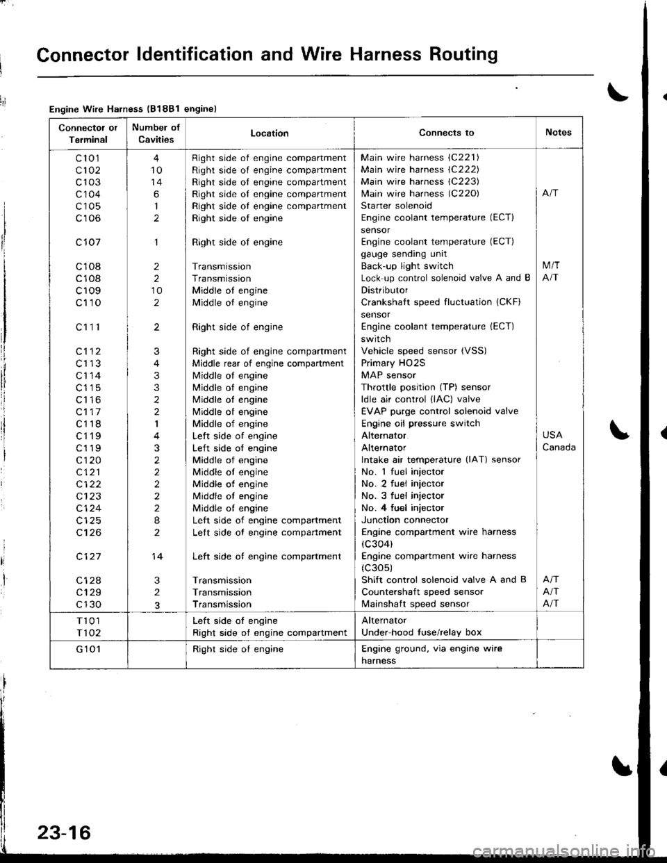
Connector ldentification and Wire Harness Routing
Connectot or
Terminal
Numbel of
CavitiesLocationConnects toNotes
c'to 1
c102
c103
c'1 04
c105
c106
c 107
c108
c108
c109
c110
c112
c113
c'r 14
c115
c116
c117
c118
ct'l9
c119
c120
c121
c122
c124
c't 26
c127
c128
c129
c130
c111
4
10
14
6
I
1
2
2
10
2
3
2
J
4
3
3
2
2
I
3
2
2
2
2
2
I
2
14
Right side of engine compartment
Right side of engine compartment
Right side ot engine compartment
Right side of engine compartment
Right side oI engine compartment
Right side of engine
Right side of engine
Transmission
Transmission
Middle ot engine
Middle ot engine
Right side of engine
Right side of engine compartment
Middle rear of engine compartment
N4iddle of engine
N4iddle ol engine
Middle oI engine
Nliddle ot engine
Middle of engine
Lelt side of engine
Left side of engine
Middle of engine
Middle oI engine
Middle of engine
Middle of engine
Middle ot engine
Left side of engine compartment
Lelt side ot engine compartment
Left side of engine compartment
Transmission
Transmission
Transmission
Main wire harness (C221)
Main wire harness (C222)
Main wire harness 1C223)
lvlain wire harness (C220)
Starter solenoid
Engine coolant temperature (ECT)
sensor
Engine coolant temperature (ECT)
gauge sending unit
Back-up light switch
Lock-up control solenoid valve A and B
Distributor
Crankshatt speed fluctuation (CKF)
sensor
Engine coolant temperature (ECT)
switch
Vehicle speed sensor (VSS)
Primary HO2S
MAP sensor
Throttle position (TP) sensor
ldle air control (lAC) valve
EVAP purge control solenoid valve
Engine oil pressure switch
Alternator
Alternator
lntake air temperature (lAT) sensor
No. 1 fuel injector
No. 2 fuel injector
No. 3 fuel injector
No. 4 fu€l injector
Junction connector
Engine compartment wire harness
(c304)
Engine compartment wire harness
(c30s)
Shift control solenoid valve A and B
Countershaft speed sensor
lvlainshaft speed sensor
M/T
NT
USA
Canada
Afi
Afi
T101
T102
Left side oI engine
Right side of engine compartment
Alternator
Under hood fuse/relay box
G'1 01Right side oI engineEngine ground. via engine wire
harness
Engine Wire Harness (B188l enginel
23-16
Page 1075 of 1681
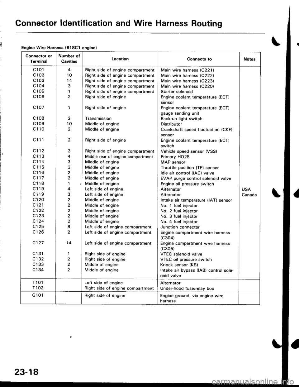
Connector ldentification and Wire Harness Routing
Engine Wire Harness (B18Cl enginel
Connectol ol
Terminal
Number of
CavitiesLocationConnects toNotes
c 101
c102
c103
c104
c105
c106
c101
c108
cr09
c110
c'r 11
cl12
c1't3
c114
c115
c116
cl17
c118
c119
c119
c120
cI2'l
cl24
c126
c127
cl31
c132
c133
c134
10
14
3
1
2
1
2
10
2
'I
3
2
2
2
I
1
2
2
?
3
2
14
Right side of engine compartment
Right side of engine compartment
Right side of engine compartment
Right side ol engine compartment
Right side of engine compartment
Righr side oI engine
Right side of engine
Transmission
Middle of engine
Middle of engine
Right side of engine
Right side of engine compartment
Middle rear of engine compartment
Middle of engine
Middle of engine
Middle of engine
Middle of engine
i/iddle of engine
Left side ot engine
Lelt side ot engine
Middle ot engine
Middle of engine
Middle of engine
Middle of engine
Middle of engine
Left side of engine companment
Left side of engine compartment
Lelt side of engine compartment
Right side of engine
Right side of engine
Middle of engine
Middle of engine
lvlain wire harness (C221 )
Main wire harness {C222)
Main wire harness (C223)
Main wire harness (C220)
Starter solenoid
Engine coolant temperature (ECT)
sensor
Engine coolant temperature (ECT)
gauge sending unit
Back-up light switch
Distributor
Crankshalt speed fluctuation (CKFI
sensor
Engine coolant temperature {ECT)
switch
Vehicle speed sensor (VSS)
Primary HO2S
MAP sensor
Throttle position {TP) sensor
ldle air control (lAC) valve
EVAP purge control solenoid valve
Engine oil pressure switch
Alternator
Alternator
Intake air temperature llAT) sensor
No. 1 fuel injector
No. 2 fuel injector
No. 3 tuel injector
No. 4 tuel injector
Junctron connector
Engine compartment wire harness(c304)
Engine companment wire harness(c30s)
VTEC solenoid valve
VTEC oil pressure switch
Knock sensor (KS)
Intake air bypass {lAB) control sole-
noid valve
USA
Canada
T101
r 102
Left side ot engine
Right side of engine compartment
Alternator
Under-hood fuse/relay box
G 101Right side of engineEngine ground, via engine wire
naaness
23-18