radiator HONDA INTEGRA 1998 4.G Repair Manual
[x] Cancel search | Manufacturer: HONDA, Model Year: 1998, Model line: INTEGRA, Model: HONDA INTEGRA 1998 4.GPages: 1681, PDF Size: 54.22 MB
Page 1049 of 1681
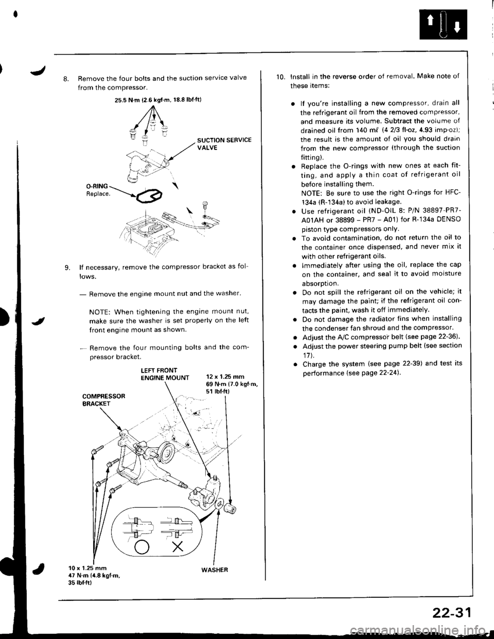
J8. Remove the four bolts and the suction servtce valve
from the compressor.
25.s18.8 tbf.ft)N.m {2.6 kgt.m,
A\
-/ l=\'zI
i:-
9.
SUCTION SERVICEVALVE
O-RING \Benrace. --'.l4p
lf necessary, remove the compressor bracket as fol
- Remove the engine mount nut and the washer'
NOTE: When tightening the engane mount nut,
make sure the washer is set properly on the left
front engine mount as shown.
- Remove the four mounting bolts and the com-
pressor bracket.
LEFT FRONTENGTNE MOUNT 12 x 1.25 mm
I
69 N.m {7.0 kg{.m.s1 rbt.ft)
10 x 1.25 mm47 N.m (4.8 kgf.m.35 rbf.ftt
10. lnstall in the reverse order of removal. Make note of
these rtems:
) lf you're installing a new compressor, drain all
the refrigerant oil from the removed compressor,
and measure its volume, Subtract the volume of
drained oil from 140 m{ 14 2/3ll.oz,4.93 imp.oz);
the result is the amount of oil you should drain
from the new compressor (through the suction
{itting).
r Replace the O-rings with new ones at each fit-
ting, and apply a thin coat of refrigerant oil
before installing them.
NOTE: Be sure to use the right O-rings for HFC-'t34a (R-134a) to avoid leakage.
. use refrigerant oil (ND-OlL 8: P/N 38897 PR7-
A0IAH or 38899 - PR7 - A01) for R-'134a DENSO
piston type compressors onlY.
. To avoid contamination, do not return the oil to
the container once dispensed, and never mix it
with other refrigerant oils.
. lmmediately after using the oil, replace the cap
on the container, and seal it to avoid moisture
aDsorDt|on.
. Do not spill the refrigerant oil on the vehicle; it
may damage the paint; if the refrigerant oil con-
tacts the Daint, wash it off immediately.
. Do not damage the radiator fins when installing
the condenser fan shroud and the compressor.
. Adjust the Ay'C compressoi belt {see page 22-36J
. Adjust the power steering pump belt (see section
17J.
. Charge the system (see page 22-39) and test its
performance {see Page 22-24).
WASHER
22-31
Page 1055 of 1681
Condenser
J
Replacement
RADIATOR UPPERMOUNT BRACKETS
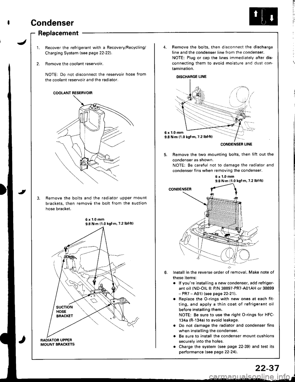
Recover the refrigerant with a Recovery/Recycling/
Charging System lsee page 22-221.
Remove the coolant reservoir.
NOTE: Do not disconnect the reservoir hose from
the coolant reservoir and the radiator.
Remove the bolts and the radiator upper mount
brackets. then remov6 the boll from the suction
hose bracket.
COOLANT RESERVOIR
6x1.0mm9.8 N'm 11.0 kgf'm, ?.2lbf'ft)
4. Remove the bolts, then disconnect the discharge
line and the condenser line from the condenser.
NOTE: Plug or cap the lines immediately after dis-
connecting them to avoid moisture and dust con'
tamination.
DISCHARGE LINE
6x1.0mm9.8 N.m {1.0 kgj'm, 7.2 lbl'ft)
5. Remove the two mounting bolts, then lift out the
condenser as shown.
NOTE: Be careful not to damage the radiator and
condenser fins when removing the condenser.
6x1.0mm9.8 N m 11.0 kgf m, 7.2 lbf ft)
lnstall in the reverse order of removal. Make note of
these items;
. lf you're instslling a new condenser, add refriger-
ant oil (ND-olL 8: P/N 38897-PR7-A01AH or 38899- PR7 - A01) (see page 22-211.
. Replace the O-rings with new ones at each fit-
ting, and apply a thin coat of refrigerant oil
before installing them.
NOTE: Be sure to use the right O-rings for HFC-
134a (R-1344) to avoid leakage.
a Do not damage the radiator and condenser fins
when installing the condenser.
o Be sure to install the condenser mount cushions
securely into the holes.
. Charge the system {see page 22-39) and test its
performance (see page 22-241.
CONOENSER LINE
22-37
Page 1064 of 1681
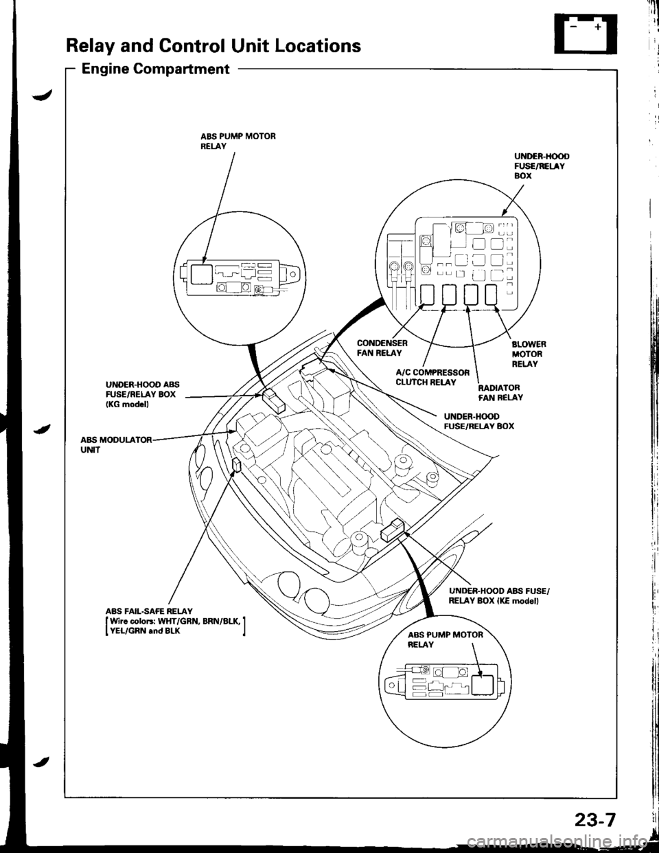
Relay and Control Unit Locations
Engine Compartment
ABS PUMP MOTORRELAY
FAN RELAY
UNDER.HOOD AB{iFUSE/RELAY BOXIKG mod.ll
A/C COMPRESSORCLUTCH RELAYRADIATORFAN BELAY
UNDER.H(X)DFUSE/RELAY BOX
A&S MODULAUNIT
UNDER.HOOD ABII FUSE,/RELAY BOX {KE modoll
----ar:l
--r: u
D
tr
L]
ABS PUMP MOTOR
23-7
Page 1079 of 1681
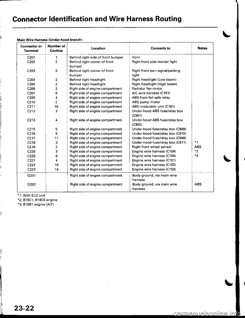
Connector ldentification and Wire Harness Routing
Main Wire Harness (Under-hood branchl
Conneqtor or
Terminal
Number ol
CavitiesLocationConnests toNotes
c201
c202
c203
c204
c205
c206
c207
c208
c210
c211
c213
c215
c216
c211
c218
c2r 9
c220
c220
c221
c222
c223
1
2
2
2
2
8
2
10
5
9'11
3
2
3
6
10
14
Behind right side of front bumper
Behind right corner of front
bumper
Behind right corner of front
DUmper
Behind right headlight
Behind right headlight
Right side of engine compartment
Right side of engine compartment
Right side of engine compartment
Right side of engine compartment
Right side of engine compartment
Right side of engine compartment
Right side ot engine compartment
Right side of engine compartment
Right side of engine compartment
Right side of engine compartment
Right side of engine compartment
Right side of engine compartment
Right side of engine compartment
Right side oI engine companment
Right side ot engine compartment
Right side ot engine compartment
Right side of engine compartment
norn
Right front side marker light
Right front turn signaUparking
lig ht
Right headlight (Low beam)
Right headlight (High beam)
Radiator lan motor
A"/C wire harness (C151)
ABS front fail safe relay
ABS pump motor
ABS modulator unit (C151)
Under-hood ABS fuse/relay box(c901)
Under-hood ABS fuse/relay box
{c902}
Under-hood fuse/relay box (C909)
Under-hood fuse/relay box (C910)
Underhood fuse/relay box (C908)
Under-hood fuse/relay box (C911)
Right front wheel sensor
Engine wire harness {C104)
Engine wire harness (C104)
Engine wire harness (C101)
Engine wire harness {C102)
Engine wire harness (C103)
*1
ABS
G201
G202
Right side of engine compartment
Right side of engine compartment
Body ground. via main wire
narness
Body ground, via main wire
harness
ABS
+1:With ELD unit*2: B18C't, 818C5 engine*3: 81881 engine (A,/T)
23-22
Page 1110 of 1681
J
)1 -
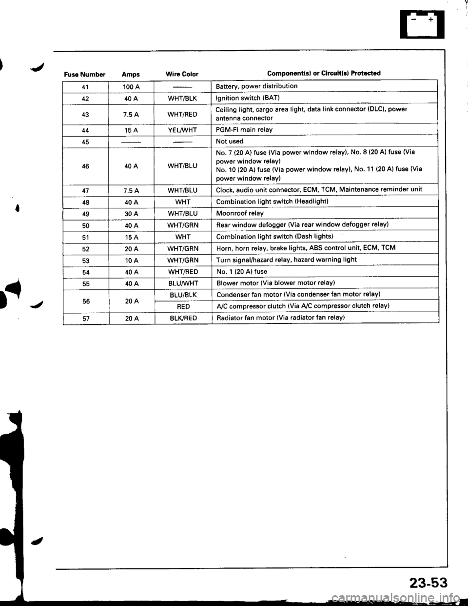
Fuso NumborAmpsWir€ ColorComponent(s) or Circuh(rl Protastcd
41100 ABattery. power distribution
4240AWHT/BLKlgnition switch (BAT)
437.5 AWHT/REDCeiling light, cargo area light, data link connector (DLCl, power
antenna connector
44't5 AYEL/WHTPGM-Fl main relay
45Not used
4640AWHT/8LU
No. 7 (20 A) fuse (Via power window relay), No. 8 (20 A) tuse (Via
power window relay)
No. 10 (20 A) fuse (Via power window relay), No. 11 (20 A) fuse (Via
power window relay)
417.5 AWHT/BLUClock,8udio unit connector, ECM, TCM, Maint€nance reminder unit
4840AWHTCombination light switch (Headlight)
4930AWHT/BLUMoonroof relay
5040AWHT/GRNRear window defogger {Via rear window defogger relay)
51154WHTCombination light switch (Dash lights)
20AWHT/GRNHorn, horn relay, brake lights, AgS control unit, ECM, TCM
10AWHT/GRNTurn signal/hazard relay, hazard warning light
5440AWHT/flEDNo. 1 (20 A) fuse
40ABLU/WHTBlower motor (Via blower motor relsy)
56204BLU/BLKCondenser fan motor (Via condenser {an motor relay)
REDA,/C compressor clutch (via Ay'c comp.essor clutch relay)
57204BLVREDRadiator f8n motor (Via radiator fan relay)
23-53
Page 1112 of 1681
\
I
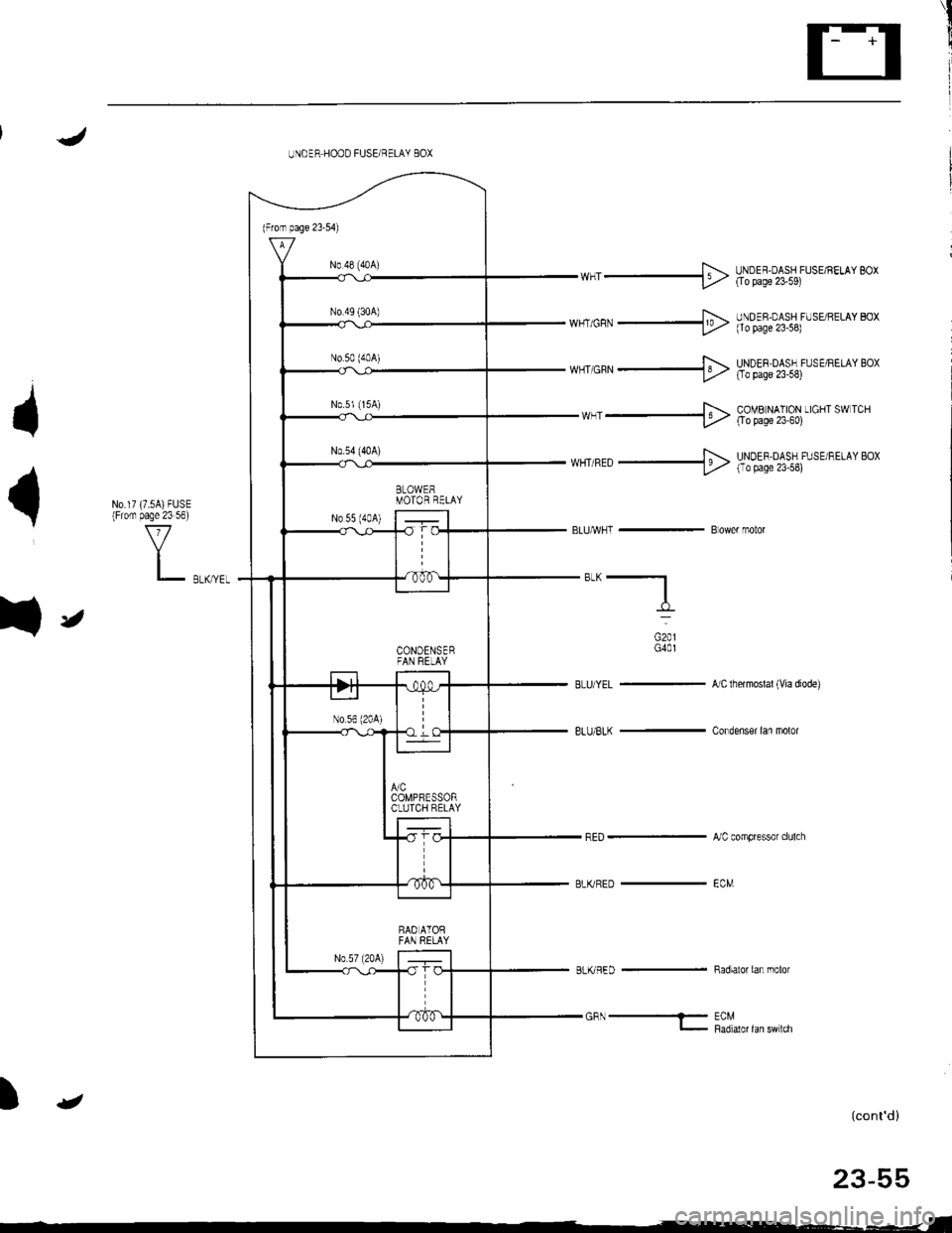
UNOER HOOD FUSE/RELAY BOX
t
{
fr
wHr _+> HtXl!;%,'$1r.,',"' *,
F.-wr cn,r _l9> l,)ooll;%,r$lrr. rr,or ro,
*,,'orn. ---$ H?!!;oA%iu'n"*"o'
wHr -+ &?Tll:11$ uo""* "*
N0.17 (7.5A)FUSE(Fiom page 23 56)
V
L r,*,rr,
**, orn N u-NoEF DASF FlrsE RE'AY Boxt'/' I aaaqe zJ''L
BLUA/VHI - B ower motor
"*-f_
oro,G40l
BLU/YEL -'ncthermoslal(viadiode)
8LU/BLK - Condenser lan molor
,JC compressor clulch
BLKRED _ €CM
BLKRED - Radiatorian molor
GFN- EcMl- P36,r1ot 1"n t'n '"n
(cont'd)
23-55
_-_ _-.-
Page 1126 of 1681
1
I
PowerRelays
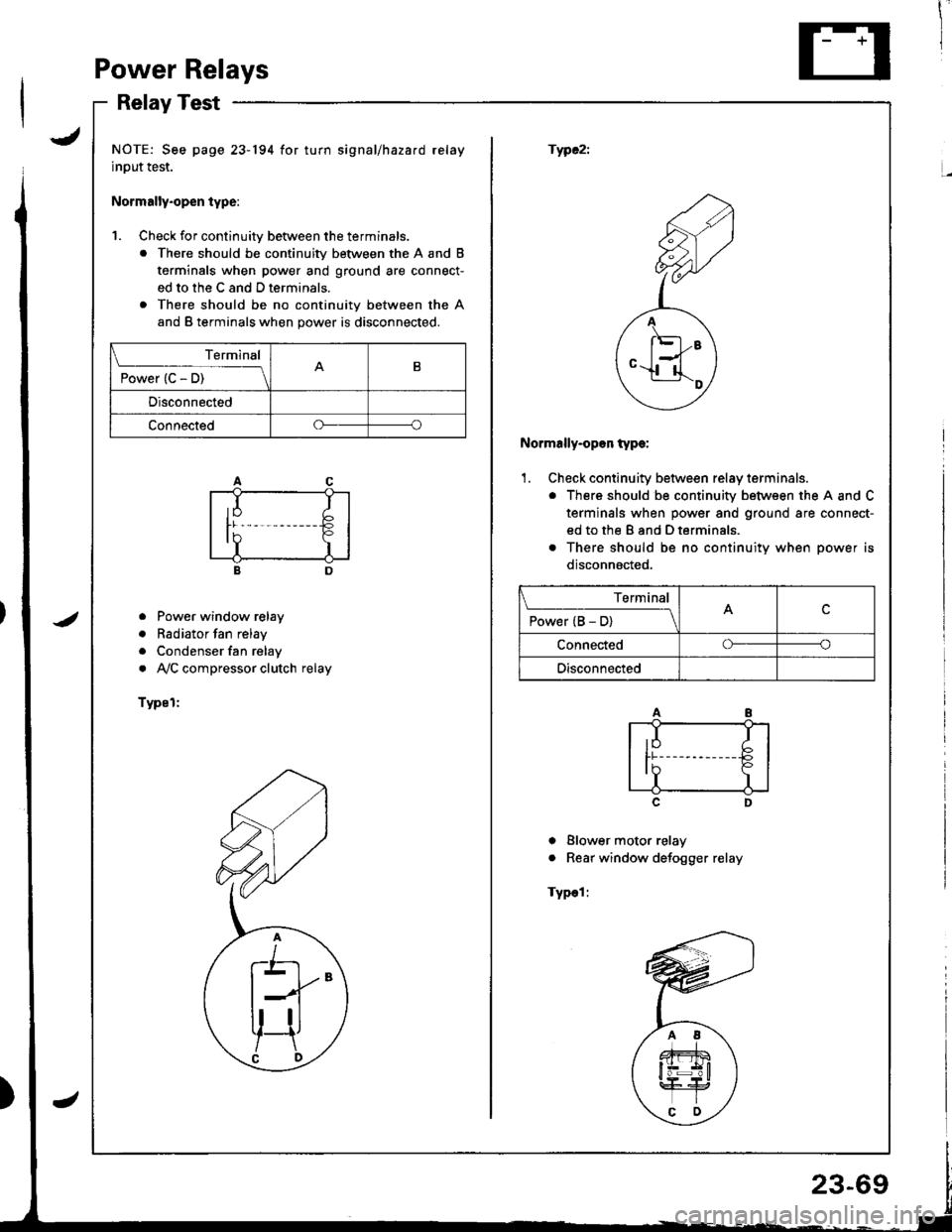
RelayTest
JNOTE: See page 23-194 for turn signal/hazard relay
input test.
Normally.open type:
fWC2i
1. Check for continuitv between the terminals.
. There should be continuity between the A and B
terminals when power and ground are connect-
ed to the C and D terminals.
. There should be no continuity between the A
and B terminals when power is disconnected.
<2
F;Z
,,A
/ l'El--E \
ey
Normally-opon type:
'1. Check continuity between relay terminals.
. There should be continuity between the A and C
terminals when power and ground are connect-
ed to the B and D terminals.
o There should be no continuitv when oower is
disconnacted,
o Power window relay
. Radiator fan relay
. Condenser fan relay
. AVC compressor clutch relay
Typel:
c
I Blower motor relay
. Rear window defogger relay
Typel:
Terminal
P";(c5t--__\B
Disconnected
Connectedoo
Terminal
P"*"r(B5-lc
Connectedoo
Disconnected
Page 1162 of 1681
{
t
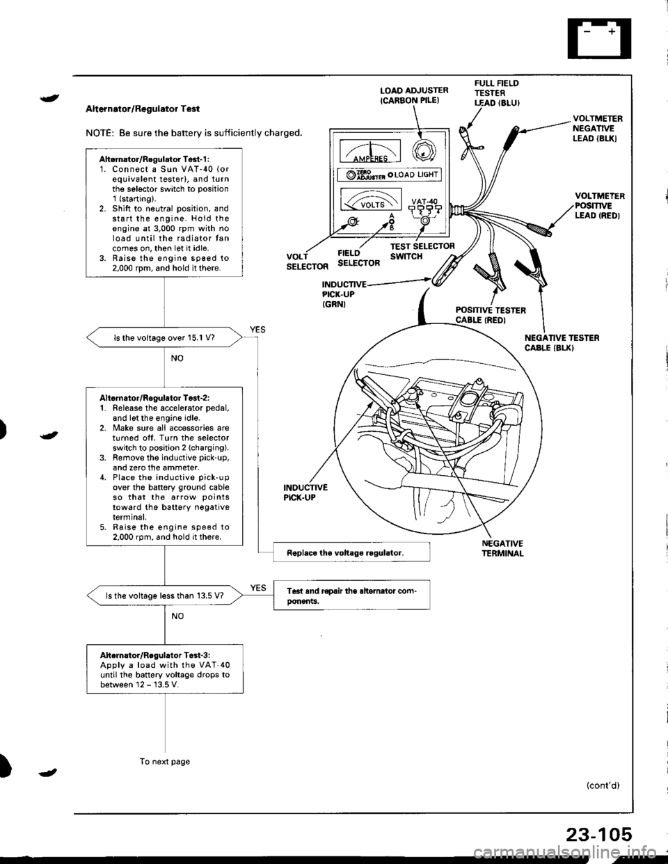
Alternator/Regulator Test
NOTE: 8e sure the battery is sufficiently charged.
LOAO ADJUSTER
ICARBON PILE)
FULL FIELDTESTERT.EAD (8LU)
POSITIVE TESTERCABLE IREDI
NEGATIVETERMINAL
VOLTMETERNEGATIVELEAO {BL|(}
VOLTMEIERPOSmVELEAD IREDI
FIELOSELECTOR
TEST SELECTORswtTcHVOLTSELECTOR
INDUCTIVEPICK.UP
INDUCTIVEPICK.UPIGRNI
NEGANVE TESTERCABLE IBLKI
)
)
{cont'd)
23-105
Ahernator/Regulator Tosl-1 :1. Connect a Sun VAT-40 (or
equivalent testerl, and turnthe selector switch to position'1 (starting).
2. Shift to neutral position, andstart the engine. Hold theengine at 3,000 rpm with noload until the radiator tancomes on, thon let it idle.3. Raise the engine sp€ed to2,000 rpm, and hold it there.
ls the voltage over 15.1 V?
Altsrnator/Rogulator Test-z:1. Release the accelerator pedal,
and let the engine idle.2, Make sure all accessories areturnod off. Turn the selectorswitch to position 2 (charging).
3. Remove the inductive pick-up,
and zero the ammeter.4. Place the inductive pick-up
over the battery ground cableso that the arrow points
toward the batterY negativeterminal,5. Raise the engine speed to2.000 rpm, and hold it there.
ls the voltage less than 13.5 V?
Ahelnstor/Regulator T$t-3iApply a load with the VAT-40until the battery voltage drops tobetween 12 - 13.5 V.
To next page
-
i-
Page 1173 of 1681
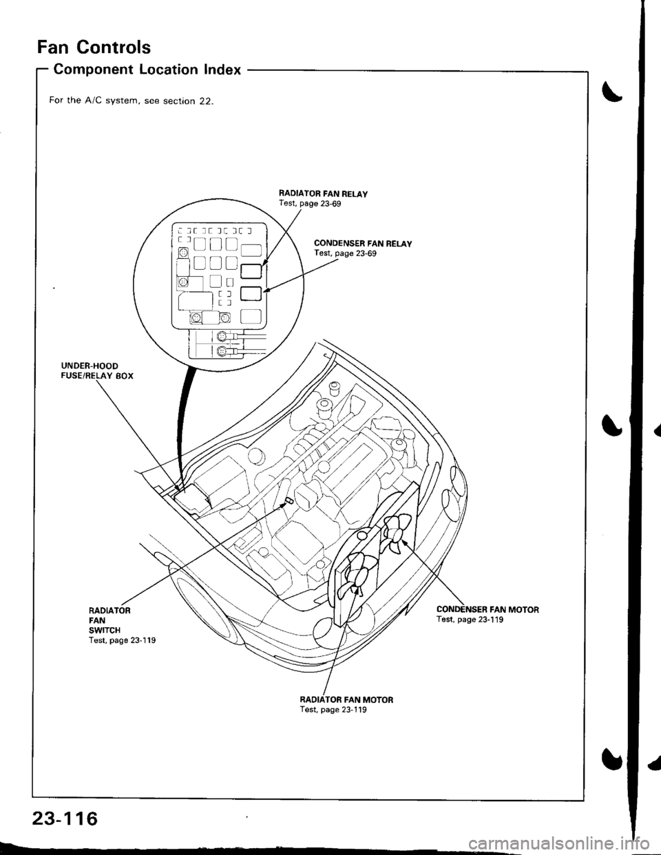
Fan Controls
RADIATORFANswtTcHTest, page 23-119
Component Location Index
For the A/C system, see section 22.
UNDER-HOODFUSE/RELAY BOX
CONDENSER FAN RELAYTest, page 23-69
RADIATOR FAN RELAYTest, page 23,69
FAN MOTORTest, page 23-119
TOR FAN MOTORTest, page 23,119
: lt tt tt tt l
c=, Ll L-t t lf l]-]l
f1 a l f -r a'r -
I i I r""""rlla-t fr -
a tL) | |Irt -
1/^ l/-\ltr.z{ N/ L
Page 1174 of 1681
![HONDA INTEGRA 1998 4.G Repair Manual Circuit Diagram (Without A/Cl
UNOEF.OASHFUSE,NELAY BOX
|-;ffi;I-YELf\-.rl]-t
BTKEL -l
RAOIATORFANS\,YITCHfoN : above )(199F (93C)J
BLIVREO
BLK
I
G201G401
IGNITION SWITCH
N0.41 (lmAl No.42 (104)
RAD HONDA INTEGRA 1998 4.G Repair Manual Circuit Diagram (Without A/Cl
UNOEF.OASHFUSE,NELAY BOX
|-;ffi;I-YELf\-.rl]-t
BTKEL -l
RAOIATORFANS\,YITCHfoN : above )(199F (93C)J
BLIVREO
BLK
I
G201G401
IGNITION SWITCH
N0.41 (lmAl No.42 (104)
RAD](/img/13/6069/w960_6069-1173.png)
Circuit Diagram (Without A/Cl
UNOEF.OASHFUSE,NELAY BOX
|-;ffi;I-YELf\-.rl]-t
BTK'EL -l
RAOIATORFANS\,YITCHfoN : above )(199'F (93'C)J
BLIVREO
BLK
I
G201G401
IGNITION SWITCH
N0.41 (lmAl No.42 (104)
RADIATORFANRELAY
23-117
.l