radiator HONDA INTEGRA 1998 4.G Owner's Guide
[x] Cancel search | Manufacturer: HONDA, Model Year: 1998, Model line: INTEGRA, Model: HONDA INTEGRA 1998 4.GPages: 1681, PDF Size: 54.22 MB
Page 353 of 1681
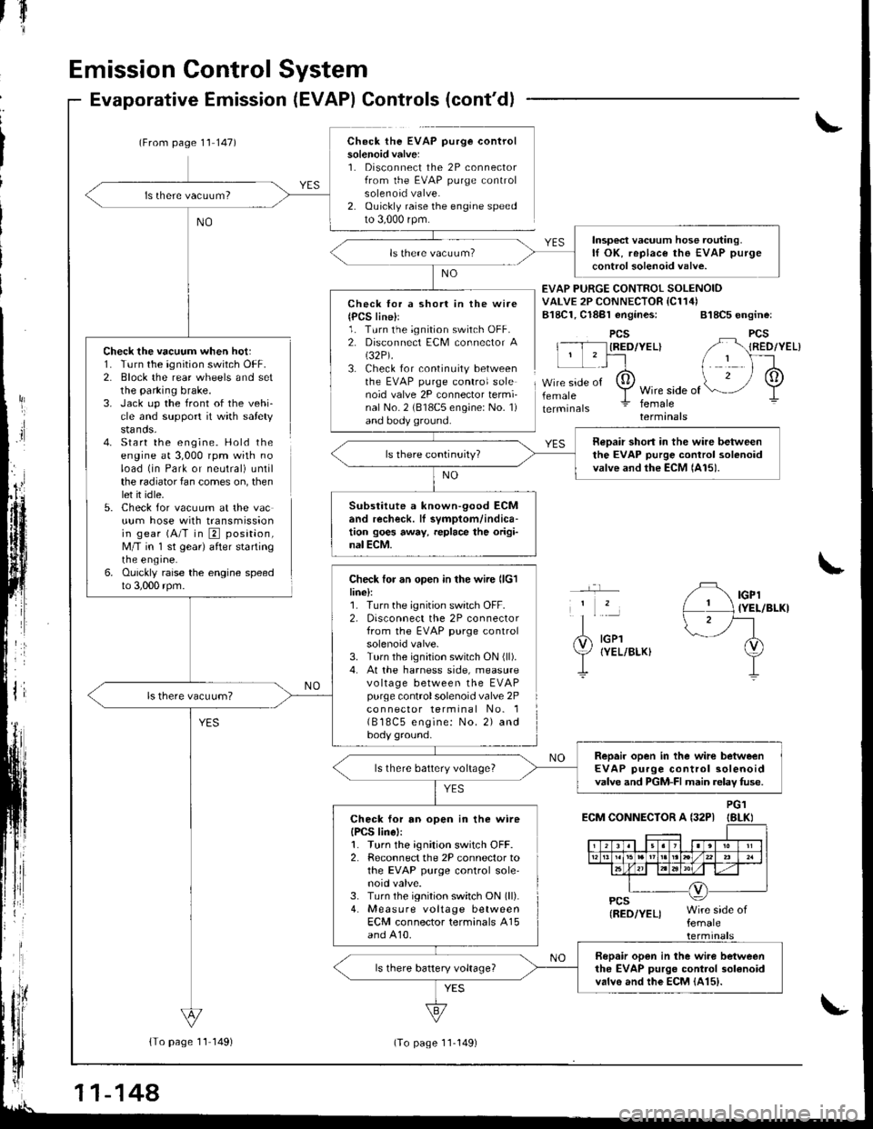
Emission Control System
Check the vacuum when hot:1. Turn the ignition switch OFF.2. Block the rear wheels and setthe parking brake.3. Jack up the front of the vehi-cle and support it with safetystands.4- Start the engine. Hold theengine at 3,000 rpm with noload (in Park or neutral) untilthe radiator fan comes on, thenlet it idle.5. Check for vacuum at the vacuum hose with transmissionin gear (A/T in E position,M/T in 'l st gear) after startingrne engrne.6. Ouickly raise the engine speedto 3,000 rpm.
Evaporative Emission (EVAP) Controls (cont'd)
(From page 1'l 147)Check the EVAP purge controlsolenoid valve:1. Disconnect the 2P connectorfrom the EVAP purge controlsolenoid valve.2. Ouickly raise the engine speedto 3,000 rpm.
{To page 11 149)
tfl'I
Check lor a short in the wire{PCS line}l1. Turn the ignition switch OFF.2. Disconnect ECM connector A(32P).
3. Check for continuity betweenthe EVAP purge control solenoid valve 2P connector termi-nal No. 2 (818C5 engine: No. 1)and body ground.
Check for an open in the wire llclline):1. Turn the ignition switch OFF.2, Disconnect the 2P connectorfrom the EVAP purge controlsolenoid valve.3. Turn the ignition switch ON (ll).
4. At the harness side, measurevo ltage between the EVAPpurge controlsolenoid valve 2Pco n nector terminal No. 1( B 18C5 engine: No. 2) andbody ground.
EVAP PURGE CONTROI SOLENOIDVALVE 2P CONNECTOR IC114)B18C1, Cl8Bl engines: 818C5 engine:
PCSIRED/YEL}
femaleWire side offemaleterminals
YES
IGPl{YEL/BLKI
IGPlIYEL/BLKI
ECM CONNECTOR A {32PIPG1IBLKI
Insp€ct vacuum hose routing.lf OK, replace the EVAP purge
control solenoid valve.
neDair short in the wire betweenthe EVAP purge control solenoidvalve and the ECM lAl5).
Substitute a known-90od ECMand recheck. lI symptom/indica-tion goes away, replace the origi-nal ECM.
Repair open in the wirc betweenEVAP purge control solenoidvalve and PGM-FI main relav fuse.ls there battery voltage?
Check for an open in the wireIPCS linel:1. Turn the ignition switch OFF.2. Reconnect the 2P connector tothe EVAP purge control sole'noid valve.3. Turn the ignition switch ON (ll).
4. Measure voltage betweenECM connector terminals A15and A10.
Bopair open in the wiro betweenthe EVAP purgo control 3olanoidvalvo and the EcM {415).
11-144
(To page 11-149)
Page 373 of 1681
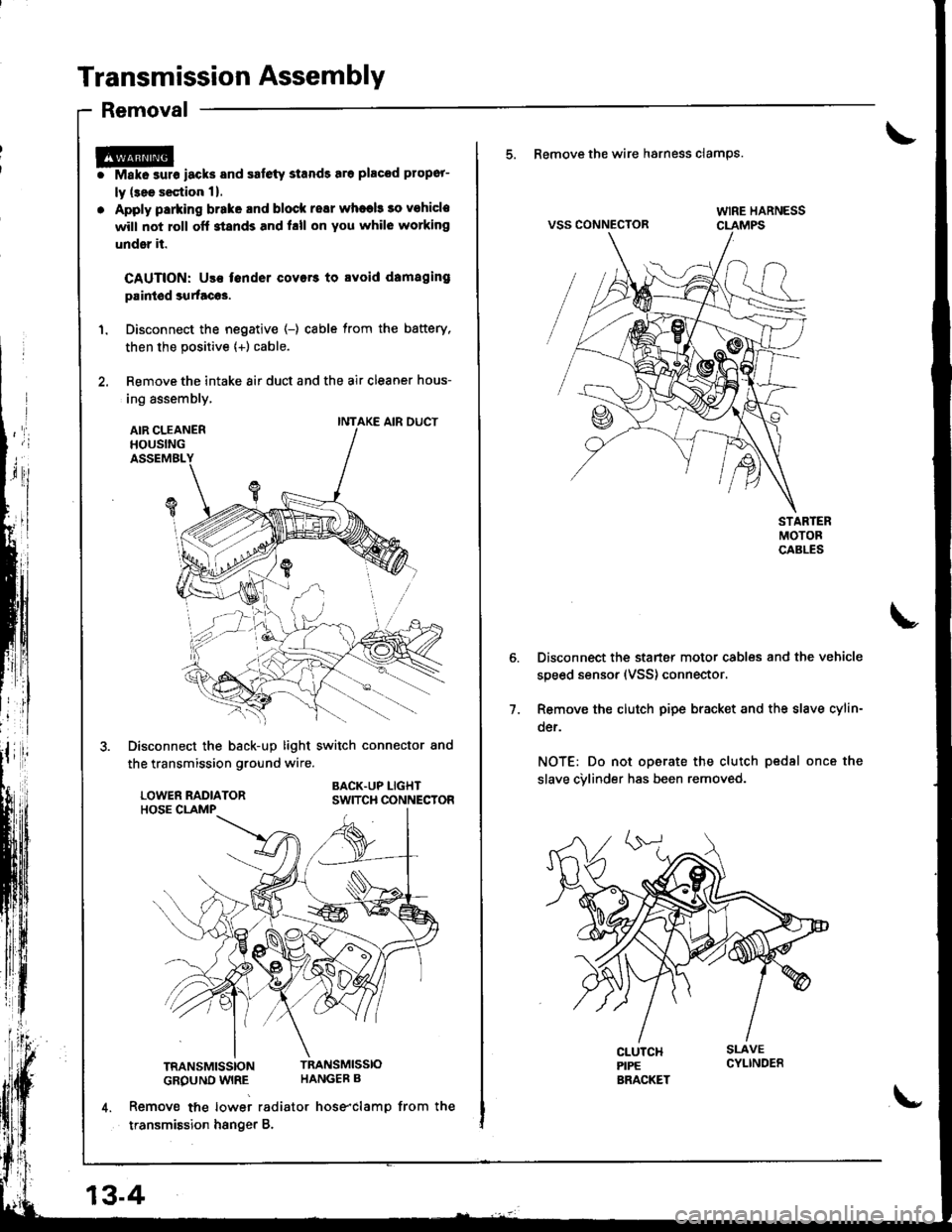
Transmission Assembly
Removal
r@i Make surs iacks and safety stands sro placod propor-
ly (3ee s€ction 1).
. Apply parking brake and block resr whaeb 30 vohicle
will not roll off stands and hll on You whil6 working
under it.
CAUTION: Use fender covers to svoid damaging
paintod surtacos.
1. Disconnect the negative (-) cable from the battery,
then the positive {+) cable.
2. Remove the intake 8ir duct and the air cleaner hous-
ing assembly,
AIR CLEANERHOUSINGASSEMBL
Disconnect the back-up light switch connector and
the transmission ground wire.
BACK.UP LIGHTSWITCH CONNECTOR
TRANSMISSIONTRANSMISSIO
GROUND WIRE HANGEB B
4. Remove tne lowei radiator hose"clamp from the
transmission hsnger B.
INTAKE AIR DUCT
13-4
\-
5. Remove the wire hsrness clamps.
VSS CONNECTOR
Disconnect the starter motor cables and the vehicle
speed sensor (VSS) connector.
Remove the clutch pipe bracket and the slave cylin-
der.
NOT€: Do not operate the clutch pedsl once the
slave cvlinder has been removed.
7.
Page 416 of 1681
Transmission Assembly
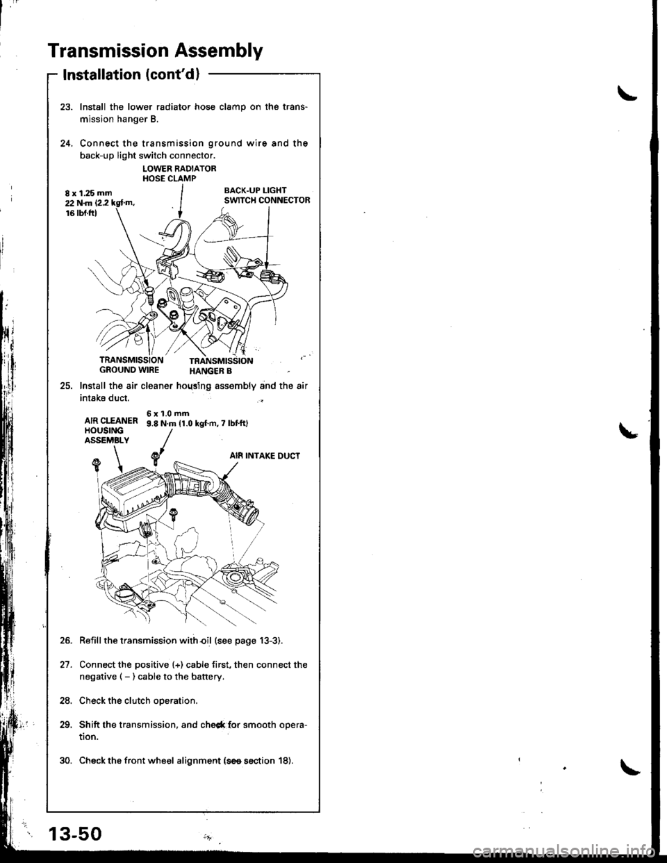
Installation (cont'd)
Install the lower radiator hose clamp on the trans-
mission hanger B.
Connect the transmission ground wire and the
back-up light switch connector.
LOWER RADIATORHOSE CLAMP
BACK.UP I-IGHTSWITCH CONNECTOR
24.
TRANSMISSIONGROUND WIRE
25. lnstall the air cleaner
intake duct.
AIR CIfANERHOUSINGASSEMBLY
HANGER B
hoqsing assembly and the air
6x1.0mm9.8 N.m 11.0 kgf.n,7 lbt'ft)
AI8 INTAKE DUCTY1
Reiill the transmission with€il (see page 13-3).
Connect the positive (+) cable first, then connect the
negative ( - ) cable to the battery.
Check the clutch operation.
Shift the transmission, and che6* {or smooth opera-
tion.
30. Check the front wheel alignment (se6 section 18).
21.
24.
13-50
Page 489 of 1681
Electrical Troubleshooting
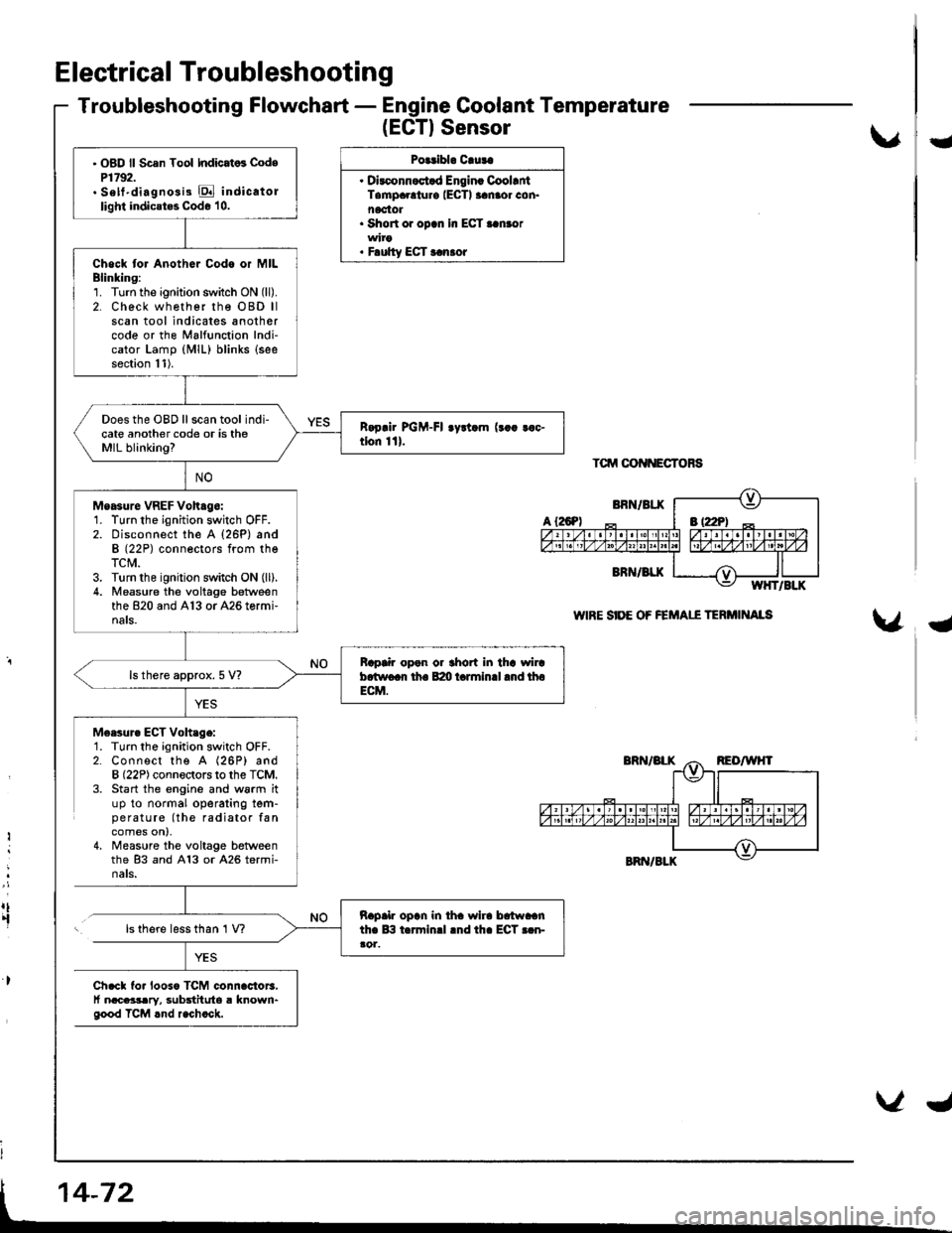
Troubleshooting Flowchart - Engine Coolant Temperature
(EGTISensor
Polribl. Cluta
. Dirconnoct.d Engin. CoollntTampaolur€ IECTI aanaor con.noctot. Short or opcn In ECT..n.or
. F.ulty ECT r.n.or
Tctrrt oot{NEcToRs
WIRE SIDE OF FEMAII TERi'IINAIS
U
{
M6esur. ECT Voh.ge:1. Turn the ignition switch OFF.2. Connect the A (26P) andB (22P) connectors to the TCM.3. Start the engine and w6rm ituP to normal operating tem-pe ratu re (the radiator fancomes on),4, Measure the voltage betweenthe 83 and A13 or A26 termi-nats.
Ii
:
rt.fls there less than 1 V?
Ch.cl fo. looso TCM connac{or3,t nacaasary, substituto a known"good TCM rnd r.chock.
' OBD ll Scsn Tool Indicat6 CodeP1792.. Sett'diagno3i3 E indicatollight indicates Code 10.
Chock tor Anothor Codo or MILBlinking:1. Turn the ignition switch ON (ll).
2. Check wh€ther rhe OBD llscan tool indicates anothercode or the Malfunction Indi-cator Lamp (MlL) blinks (see
section 11).
Does the OBD ll scan tool indi-cate another code or is theMIL blinking?
Moasure VREF Voh.go:1. Turn the ignition switch OFF.2. Disconnect the A {26P) andB (22P) conneotors from theTCM.3. Turn the ignition switch ON (ll).
4. Measu.e the voltage betweenthe 820 and A13 or A26 tormi-nals.
Bap|ir open or thort in tha wircb.two.r th. B:m t.rminll .nd thoECM.
ls there approx. 5 V?
napalr opln in iha wlra brtwaanthe lB t.rminrl lnd th. ECT r.n-ao1.
Page 493 of 1681
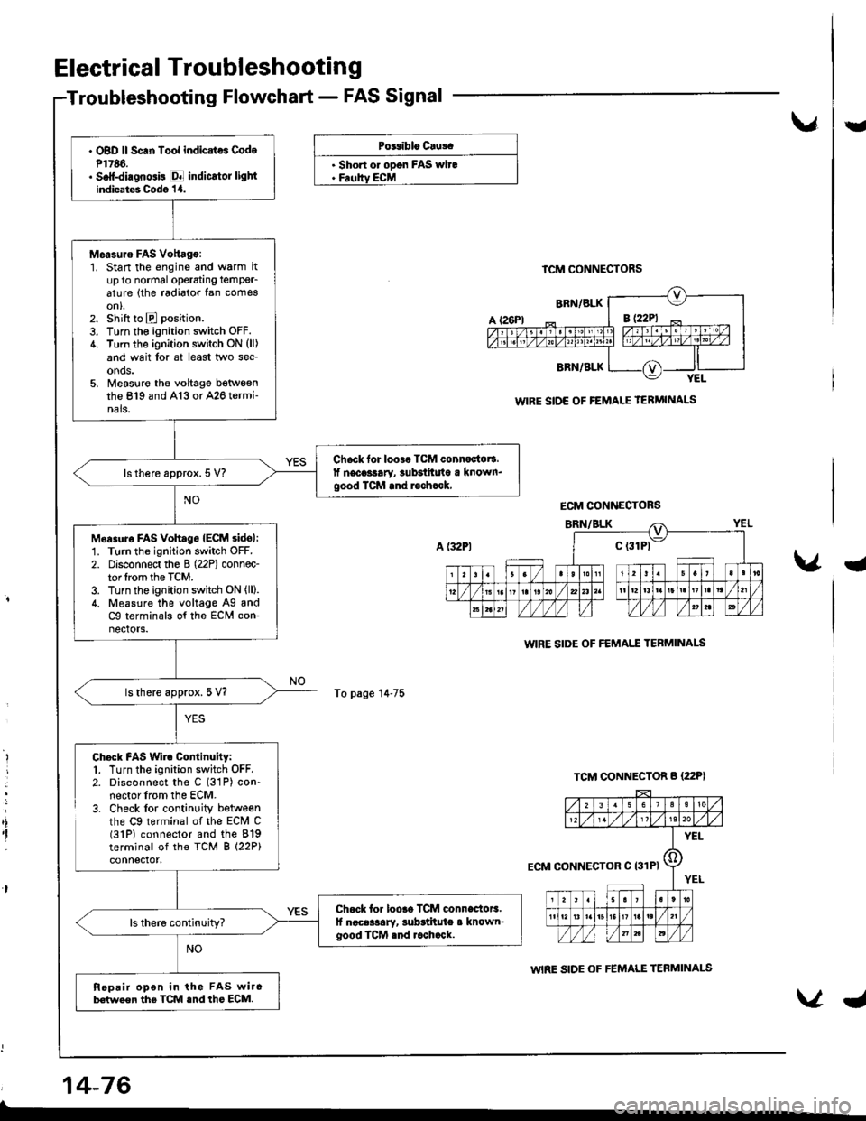
. OBD ll Scan Tool indicatcs CodeP1786.. Soff-diagnGis E indicrtor lightindicat6 Codo '1,0.
M6a3ure FAS Vottago:1. Start the engine and warm itup to normal operatang temPer_6ture (the radiator fan comeson).2. shift to E position.
3. Turn the ignition switch OFF.4. Turn the ignition switch ON (ll)
and wait lor at least two sec-onds.5. Measlre the voltage betweenthe 819 and A13 or A26 termi-nals.
Chsck for loo3r TCM connactot!.lf necoslary, lubsihuto a known.good TCM rnd r.chrck,ls there approx. 5 V?
M6asuro FAs vohagoIECM sidol:1. Turn the ignition switch OFF.
2. Disconnect the B (22P) connec-tor lrom the TCM.3. Turn the ignition switch ON (ll).
4. Measure the voltage Ag andC9 terminals of tho ECM con-nectors.
ls there approx. 5 V?
Chock for loore TCM connectoE.lf noceilary, subrtitula a known-good ICM rnd rcchock.
Repair opon in the FAS wircb€(we€n the TCM snd ths ECM.
Electrical Troubleshooting
Troubleshooting Flowchart - FAS Signal
vU
PG.iblo Cru!.
. Short o. opon FAS wira. Feoltv ECM
To page 14-75
TCM CONNECTORS
WIRE SIDE OF FEMALE TERMINALS
WIRE SIDE OF FEMAI.T TEBMINAI-S
WIRE SIDE OF FEMALE TERMINALS
a
,i,I
Chock FAS Wiro Continuity:1. Turn the ignition switch OFF.2. Disconnect the C (31P) con-nector lrom the ECM.3. Check lor continuity betweenthe C9 terminal of the ECM C(31P) connector and the 819terminal of the TCM B (22P)
14-76
ECM CONNECTORS
ECM CONNECTOR C I31P}
Page 511 of 1681
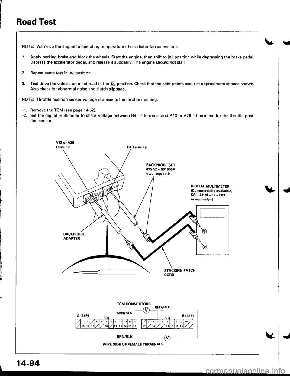
Road Test
NOTE: Warm up the engine to operating temperature (the radiator fan comes on).
1. Apply parking brake and block the wheels. Start the engine, then shift to @ position while depressing the brake pedal-
Depress the accelerator pedal, and release it suddenly. The engine should not stall.
2. Repeat same test in E position.
3. Test drive the vehicle on a flat road in the @ position. Check that the shift points occur at approximate speeds shown.
Also check for abnormal noise and clutch slippage.
NOTE: Throttle position sensor voltage represents the throttle opening.
-1. Remove the TCM (see page 14-52).-2. Set the digital multimeter to check voltage between 84 (+) terminal and A13 or A26 (-) terminal for the throttle posi-
tion sensor.
84 Terminal
DIGITAL MULTIMETER(Commercially availablelKS - AHM -32 - 003oa oquivalent
, 14-94
TCM CONNECTORS
WIRE SIDE OF FEMALE TERMINALS
i
J
Page 514 of 1681
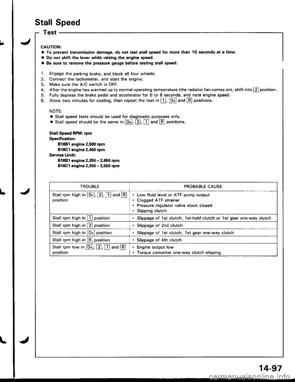
Stall Speed
V
€nt transmission damage, do not tost stall speod for mol€ than
shitt tho lever while raising the engina speed,
10 soconds at a time.
L
CAUTION:
a To prev€nt transmission damage, do not tost stall speod for mol€ than 10 soconds at a time.
a Do not shitt tho lever while raising the engina speed,
a Be suro to remove tho plossule gaugo bolore testing st8ll spe€d.
1. Engage the parking brake. and block all lour wheels.
2. Connect the tachometer, and start the engine,
3. Make sure the A/C switch is OFF.
4. After the engine has warmed up to normal operating temperature {the radiator fan comes on), shift into g position.
5. Fully depress the brake pedal and accelerator for 6 to I seconds. and note engine speed.
6. Allow two minutes for cooling, then repeat the test in [, [Dll and @ oositions.
NOTE:
a Stall speed tests should be used tor diagnostic purposes only.
. Stall speed should be the same in E, tr, tr and @ Fositions.
Stall Speed FPM: rpm
Specification:
Bl88l €ngine 2,5q) rpm
Bl8Cl engine 2.i|{10 .pm
Sorvice Limit:
81881 engins 2,350 - 2,650 rpm
Bl8Ct ongine 2,250 - 2,550 rpm
TROUBLEPROBABLE CAUSE
Stall rpm hish in E, E, I and @position
Low tluid level or ATF pump output
Clogged ATF strainer
Pressure regulator valve stuck closed
Slipping clutch
Stall rpm high in I positionSlippage of 1st clutch, 1st-hold clutch or 1st gear one-way clutch
Stall rpm high in E positionSlippage of 2nd clutch
Stall rpm high in ldnl posirionSlippage of 1st clutch. 1st gear one-way clutch
Stall rpm high in [!l positionSlippage of 4th clutch
Stall rpm low in E, E. I and @position
Engine output low
Torque convener one-way clutch slipping
14-97
Page 515 of 1681
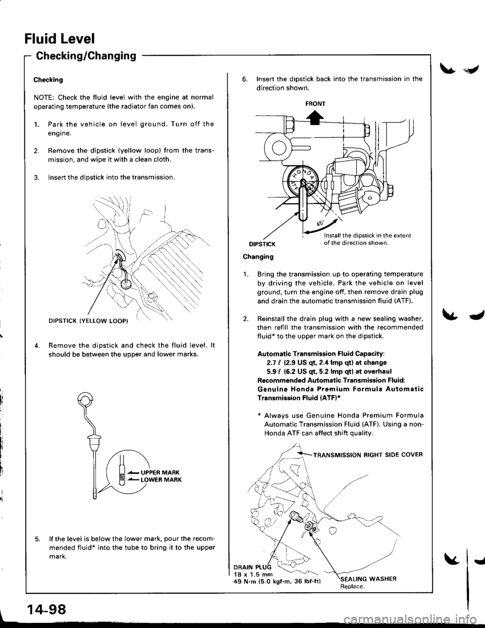
Checking/Changing
Checking
NOTE: Check the fluid level with the engine at normal
operating temperature (the radiator fan comes on).
1.
2.
Park the vehicle on level ground. Turn off the
eng I ne.
Remove the dipstick (yellow loopl from the trans-
mission, and wipe it with a clean cloth.
Insert the dipstick into the transmission.
Remove the dipstick and check the fluid level.
should be between the u9Der and lower marks.
lf the level is below the lower mark. pour the recom-
mended fluid* into the tube to bring it to the upper
mark.
DIPSTICK
UPPERLOWER
Insert the dipstick back into the transmission in the
direction shown.
DIPSTICK
Changing
DRAIN18 x 1.5 mm49 N.m 15.0 kgt.m, 36 lbf.ftl
Bring the transmission up to operating temperature
by driving the vehicle. Park the vehicle on level
ground, turn the engine off, then remove drain plug
and drain the automatic transmission fluid (ATF).
Reinstall the drain plug with a new sealing washer,
then refill the transmission with the recommended
fluid* to the upper mark on the dipstick.
Automatic Transmission Fluid Capacity:
2.7 t 12.9 US qr,2.1lmp qt) at change
5.9 / 16.2 US $. 5.2 lmp qt) at overhaul
Recommended Automatic Transmisgion Fluid:
Genuine Honda Premium Formula Automatic
Transmission Fluid (ATE*
* Always use Genuine Honda Premium Formula
Automatic Transmission Fluid (ATF). Using a non-
Honda ATF can affect shift qualitv
1.
WASHERReplace.
FRONT
Installthe dipstick in the extentof the direction shown.
Fluid Level
V*Y
\&J
, 14-98
vI
Page 516 of 1681
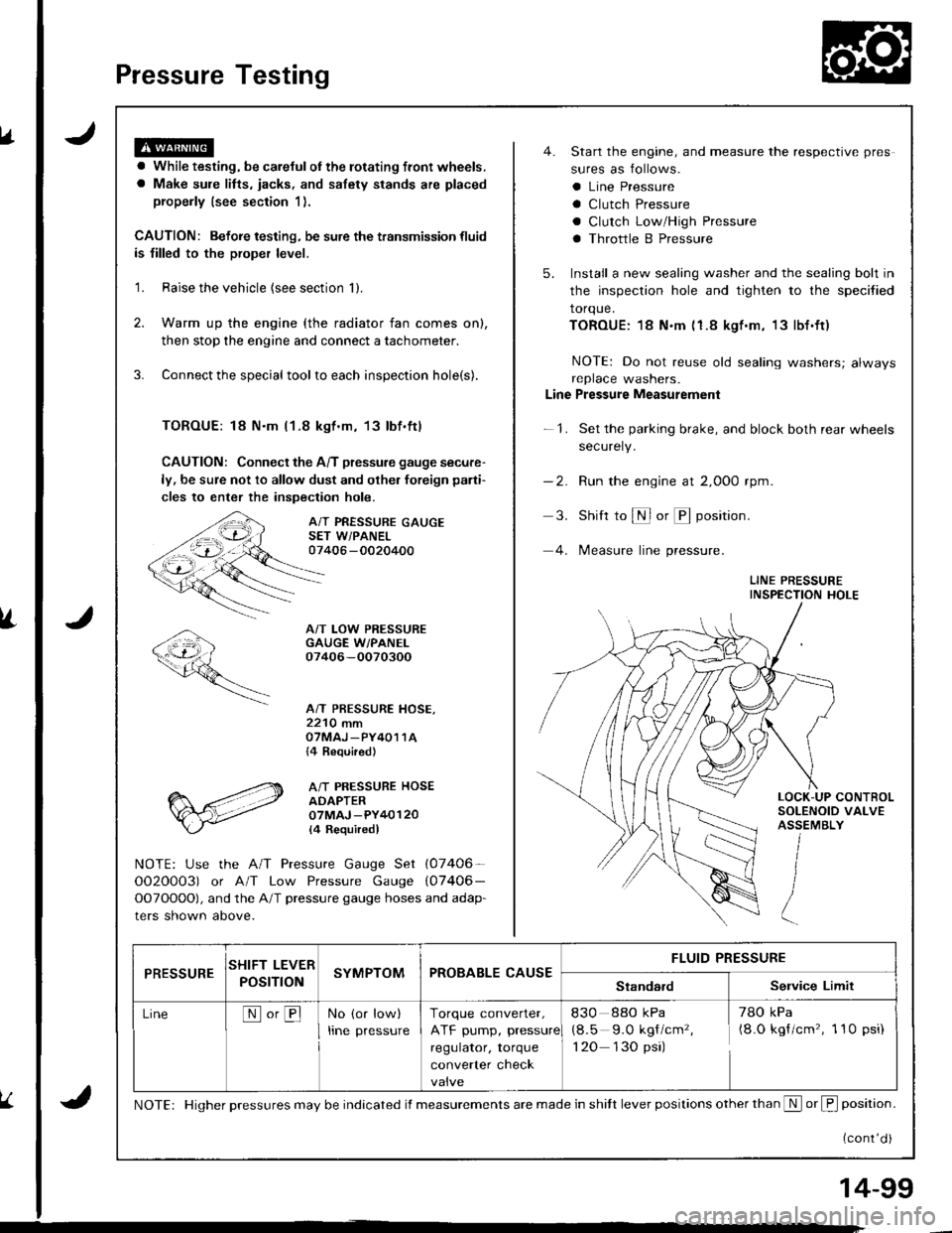
Pressure Testing
a While testing, be careJulot the rotating front wheels.
a Make sule litts, iacks, and safety stands are placed
properly (see section 1).
CAUTION: Befoie testing, be sure the transmission fluid
is filled to the proper level.
'1. Raise the vehicle {see section 'll.
2. Warm up the engine (the radiator fan comes on),
then stop the engine and connect a tachometer.
3. Connect the special tool to each inspection hole(s).
TOROUE: 18 N.m l1-8 kgt.m, 13lbf.ftl
CAUTION: Connect the A/T pressure gauge secure-
ly, be sure not to allow dust and olher foreign pani-
cles to enter the inspection hole.
A/T PRESSURE GAUGESET W/PANEL07406 -0020400
A/T LOW PRESSUREGAUGE W/PANEI.07406-OO70300
A/T PRESSURE HOSE,2210 mmOTMAJ _PY4O1 1A{4 Required}
A/T PRESSURE HOSEADAPTER07MAJ -PY40120
l4 Requiredl
NOTE: Use the A/T Pressure Gauge Set (07406-
OO2O0O3) or A/T Low Pressure Gauge (07406-
OOTOOOO), and the A/T pressure gauge hoses and adap-
ters shown above.
4. Start the engine, and measure the respective pres
sures as follows.
a Line Pressure
a Clutch Pressure
a Clutch Low/High Pressure
a Throttle B Pressure
5. Install a new sealing washer and the sealing bolt in
the inspection hole and tighten to the specified
torque.
TOROUE:18 N.m (1.8 kgf.m, 13lbf.ft)
NOTE: Do not reuse old sealing washers; alwaysreplace washers.
Line Pressure Measurement
-1. Set the parking brake, and block both rear wheels
securely.
-2. Run the engine at 2,000 rpm
3. Shift to S or @ position.
4. lMeasure line pressure.
LINE PRESSUREINSPECTION HOLE
LOCK-UP CONTROLSOLENOID VALVEASSEMBLY
PRESSURESHIFT LEVER
POST ONSYMPTOMPROBABLE CAUSEFLUID PRESSURE
StandardService Limit
LineNo,BNo (or low)
Irne pressure
Torque converter,
ATF pump, pressure
regulator, torque
converter check
830 88o kPa
(8.5 9.O kgf/cm'�,
1 20 130 psi)
78O kPa(8.O kgf/cm'�, 1 10 psi)
NOTE: Higher pressures may be indicated if measurements are made in shitt lever positions other than S or f, position.
{cont'd )
14-99
Page 1009 of 1681
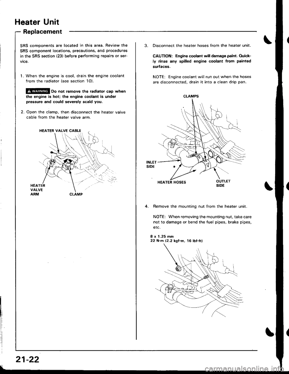
Heater Unit
Replacement
SRS components are located in this area. Review the
SRS component locatio.s, precautions, and procedures
in the SRS section (23) before performing repairs or ser-
vtce.
1. When the engine is cool, drain the engine coolant
from the radiator (see section 1O).
@ oo not remove the radiator cap when
the engine is hot; the engine coolant is undol
prsssure and could sevdely scald you.
2. Ooen the clamD, then disconnect the heater valve
cable from the heater valve arm.
HEATER VALVE CABI-E
I
i
21-22
3. Disconnect the heater hoses lrom the heater unit.
CAUTION: Engine coolant will damaga paint. Ouick-
ly rinse any spilled engine coolant from painted
sudaces.
NOTE: Engine coolant will run out when the hoses
are disconnected, drain it into a clean drip pan.
4. Remove the mounting nut from the heater unit.
NOTE: When removing the mounting nut, take care
not to damage or bend the fuel pipes, brake pipes,
etc.
8 x 1.25 mm22 N'llt. 12.2 kgl'm, 16 lbl.tl)
CLAMPS
HEATER HOSES