key HONDA INTEGRA 1998 4.G Workshop Manual
[x] Cancel search | Manufacturer: HONDA, Model Year: 1998, Model line: INTEGRA, Model: HONDA INTEGRA 1998 4.GPages: 1681, PDF Size: 54.22 MB
Page 93 of 1681
\-
L
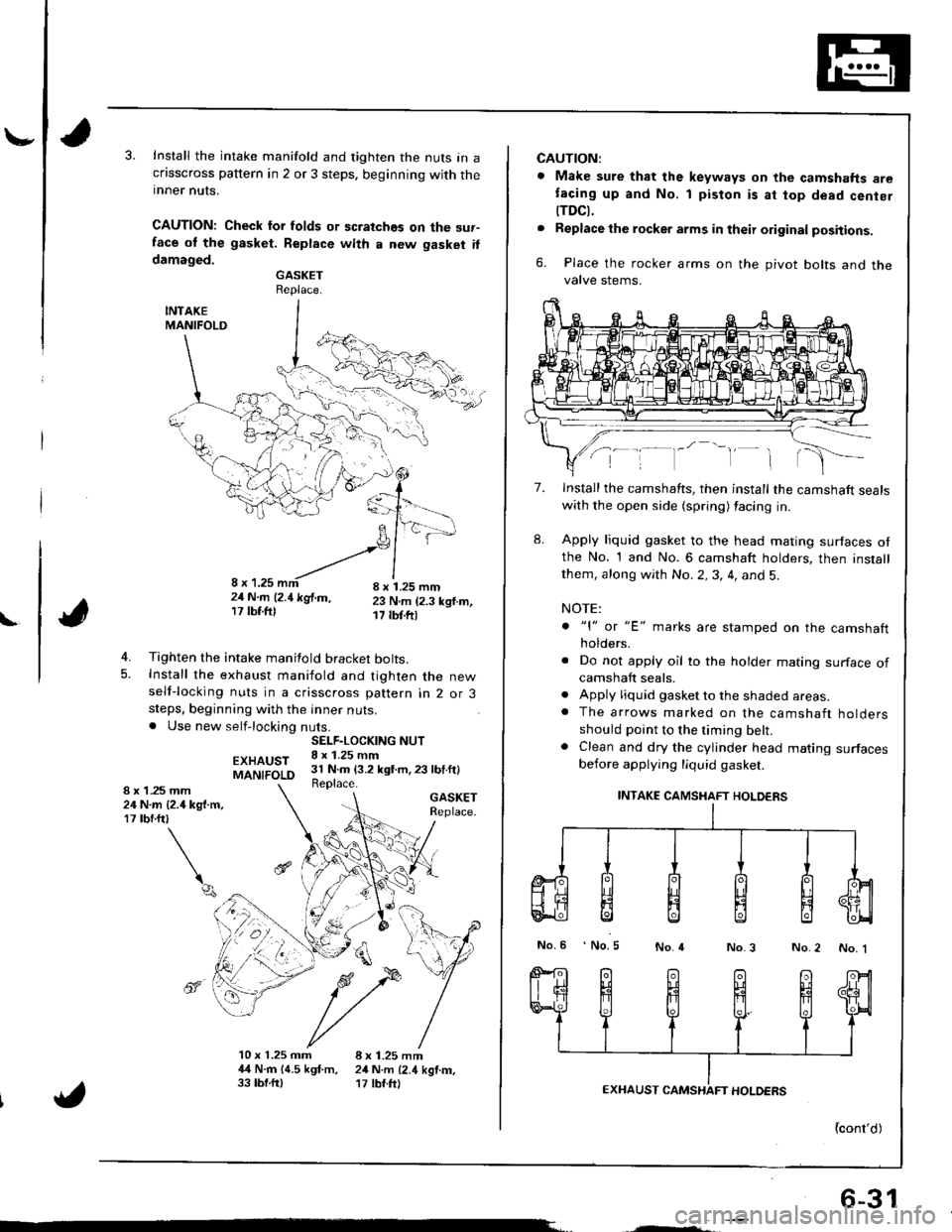
Install the intake manifold and tighten the nuts in acflsscross pattern in 2 or 3 steps. beginning with theinner nuts.
CAUTION: Check lor folds or scratches on the sur-face ol the gasket. Replace with a new gasket ildamaged.GASKETReplace.
INTAKEMANIFOLD
4. Tighten the intake manifold bracket bolts.5. Install the exhaust maniiold and tighten the newself-locking nuts in a crisscross pattern in 2 or 3steps, beginning with the inner nuts.. Use new self-locking nuts.
EXHAUSTMANIFOLD
GASKETReplace.
4
10 x 1.25 mm 8 x 1.25 mm4,{ N.rn 14.5 kgf.m, 24 N.m {2.4 kgtm,33 tbf.ftl '17 tbf.ft)
SELF.LOCKING NUT8 x 1.25 mm31 N.m (3.2 kgt m,23 lbf.ft)Replace.1 .25 mmN.m {2.4 kg{.m,rbrftt
\q
8x2417
",', r, ^-'-"-!,1,,,';-21N.m l2.1kglm, 23 N.m (2.3 ksf.m,17lbf.ftl 17 tbf.ftr
6-31
CAUTION:
. Make sure that the keyways on the camshafts aretacing up and No. 1 piston is at top dead cenier
tTDCt.. Replacethe rocker arms in their original positions.
6. Place the rocker arms on the pivot bolts and thevalve stems.
7.
8.
Install the camshafts, then install the camshaft sealswith the open side (spring) facing in.
Apply liquid gasket to the head mating surfaces otthe No. 1 and No. 6 camshaft holders, then installthem, along with No.2,3, 4, and 5.
NOTE:
. "l" or "E' marks are stamped on the camshaftholders.
. Do not apply oil to the holder mating surface ofcamshaft seals.. Apply liquid gasket to the shaded areas.. The arrows marked on the camshaft holdersshould point to the timing belt.. Clean and dry the cylinder head mating surfacesbefore applying liquid gasket.
INTAKE CAMSHAFT HOLDERS
No.6 No.5No.4No.3 No.2 No. 1
{cont'd)
Page 94 of 1681
Cylinder Head
Installation (cont'dl
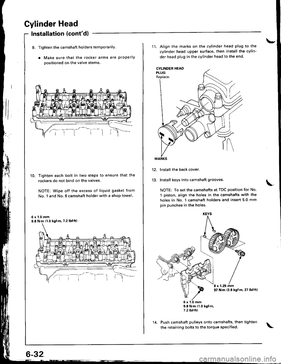
9, Tighten the camshaft holders temporarily.
a Make sure that the rocker arms are properly
positioned on the valve stems
10. Tighten each bolt in two steps to ensure that the
rockers do not bind on the valves.
NOTE: wipe off the excess of liquid gasket from
No. 1 and No. 6 camshaft holder with a shop towel
6x1.0mm9,8 N.m 11.0 kgf m, 7.2 lbt'ftl
\-
11. Align the marks on the cylinder head plug to the
cylinder head upper surface, then install the cylin-
der head plug in the cylinder head to the end.
CYLINDEB HEADPLUGReplace.
13.
lnstall the back cover.
Install keys into camshaft grooves.
NOTE: To set the camshafts at TDC position for No.
1 piston, align the holes in the camshafts with the
holes in No. 1 camshsft holders snd insert 5.0 mm
pin punches in the holes.
8 x 1.25 mmt7 N.|rl {3.8 kst.m,27 lbf.ftl
6x1.0mm9.8 N.m {1.0 kgt m.7.2 tbr.ft)
Push camshaft pulleys onto camshafts, then tighten
the retaining bolts to the torque specified.
KEYS
14.
Page 157 of 1681
NOTE:
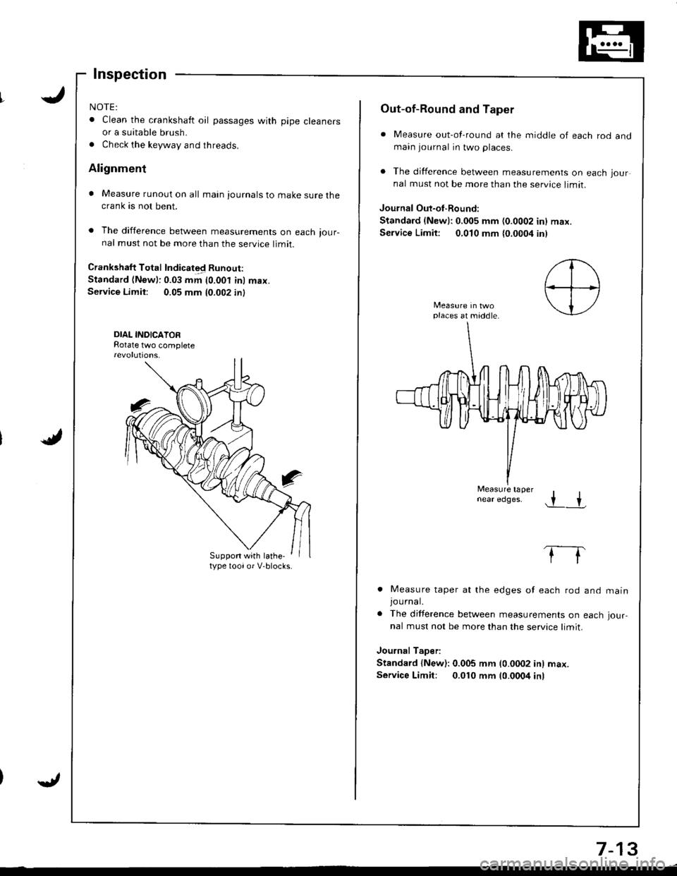
. Clean the crankshaft oil passages with pipe cleanersor a suitable brush.
. Check the keyway and threads.
Alignment
. Measure runout on all main journals to make sure thecrank as not bent.
. The difference between measurements on each ,our-nal must not be more than the service limit.
Crankshaft Total Indicated Runout:
Standard (New): 0.03 mm (0.001 inl max.Service Limit: 0.05 mm 10.002 in)
DIAL INDICATORRotate two complete
Suppon with lathe-type toolor V-blocks.
Out-of-Round and Taper
. Measure out-of-round at the middle of each rod andmain journal in two places.
. The difference between measurements on each jour
nal must not be more than the service limit.
Journal Out-oI-Round:
Standard {Newl:0,005 mm (0.0002 inl max.
Service Limit: 0,010 mm {0.0004 inl
places at middle.
Measure tapernear edges..r +
. Measure taper at the edges of each rod
JOUrnal.. The difference between measurements on
nal must not be more than the service limit.
Journal Taper:
Standard {New): 0.005 mm (0.0002 in) max.
Service Limit: 0.010 mm 10.0004 inr
and matn
each Jour-
7-13
Page 592 of 1681
Adiustment
CAUTION:
a All SRS wile harnesses are covered with yellow insu-
lation. Belore you disconnect any part ol an SRS wire
harness, disconnect the akbag connectors'
a Whenever the ignition switch is ON (ll), or has been
tumed OFF tol less than three minutes, be caletul not
to bump the SRS unit; the airbags could accidentally
deploy and cause damage or injuries'
a For additionalprecautions, referto the SRS sub-section
SBS MAIN HARNESS(Covered with yellow inslrlationl
$!@ rtl"t . "ure lifts are placed plope y lsee sec-
tion 1 l.
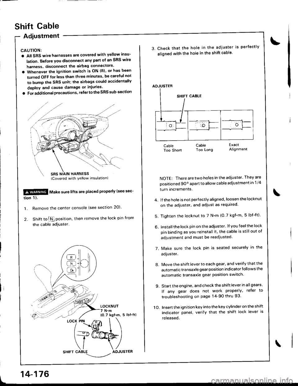
'1. Remove the center console lsee section 20)'
2. Snitt to $ position, then remove the lock pin lrom
the cable adjuster'
LOCKNUT7 N.m10.7 kgf.m, 5 lbf.fl)
t
]H
@
@
@
{l
LOCK PIN
14-176
shift cable
3. Check that the hole in the adjuster is perfectly
sligned with the hole in the shift cable'
CableToo Short
NOTE: There are two holes in the adjuster. They are
positioned 9Oo apart to allow cable adiustment in 1/4
turn Incremenrs.
4. lJ the hole is not per{ectly aligned, loosen the locknut
on the adjuster, and adiust as required.
5. Tighten the locknut to 7 N'm (0.7 kgf'm, 5lbf'ftl
6. Installthe lock pin on the adiuster. lI you feelthe lock
pin binding as Vou reinstall it, the cable is still out ot
adjustment and must be readjusted.
7. [/ake sure the lock pin is seated securely in the
aoJusrer.
8. Move the shift lever to each gear, and verify that the
automatic transaxle gear position indicator follows the
automatic transaxle gear position swatch.
9. Start the engine, and check the shift lever in allgears'
lf any gear does not work properly, refer to
troubleshooting on page 14-90 thru 93.
10. Insert the ignition key into the key cylinder on the shift
indicator panel, verify that the shift lock lever is
released.
CableToo Long
ExactAlignment
\
ADJUSTER
Page 1058 of 1681
J
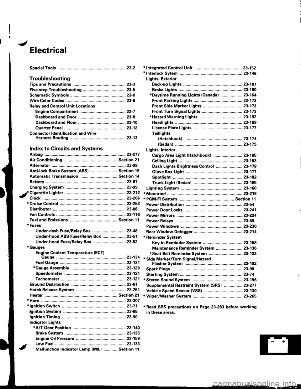
Electrical
Speciaf Toofs ..........................23-2
Troubleshooting
Tips 8nd Precautions .......................,..,.,.,.,.,......,..., 23-3
Five-step Troubleshooting ............,......,.,.,...,..,....., 23-5
Schsmatic Svmbols ...............23-6
Wire Color Code3 .. ................. 23-6
Relay and Control Unit Locations
Engine Compartment ......,.,.................,.,.,.,.,.,,,, 23-7
Dashboard and Door .........,...........,.....,.,....,.,.... 23-8
Dashboard and Floor ......................................... 23-10
Ouarter Pan€f .,,.,...,.,..,...,,,23-12
Connector ldontification and WireHarness Routing ......,.,......23-'13
Index to Circuits and Systems
Airbag
* Integrated Control Unit .....,.,.,.....23-152* Interlock Sytem .,...,.,...........,. 23.146
Lights, Exterior
Eack-up LighB ..................23.187
Brake Ligh$ ......................23-190*Daytime Running Lights (Canada) ................... 23"164
Front Parking Lights .......................................... 23-173
Front Side Marker Lights .................................. 23-173
Front Turn Signal Lights ..................-.......,...,.,. 23-173* Hazard Warning Lights ....................,........,....... 23-192
Headlights.....23-169
23-253 powerDistribution..................... 23-5/r
Air Conditioning.....,....... Soction 21
Alternator ..........,................... 23.99
iCigarette Lighter .........23-212
*Cruise Control
Distributor
'.'.,.'.'.,.'...,,,,.,''.'.,.',.'''.' 23.277
.............................. 23.88
................... 23-90lgnition Timing ......
Indicator Lights
Key-in Reminder System
Maintenance Reminder System*Seat Belt R€mindor System .,...........................* Side Marker/Turn Signal/HazardFlashcr Svstem .................23-192
Spark Plugs ............................23-98
Starting System .....................23-74* Stereo Sound System ...,......,..........,...,......,.,.,.,..,., 23-196
Supplemental Restraint System (SRS) ................ 23-277
Vshicle Speed Sensor (VSS) ................................. 23.130r Wiper/Washer System .........................................., 23-265
*Read SRS precautions on Psge 23-283 before working
in those areas,
23-154
23.136
23"133
Page 1062 of 1681
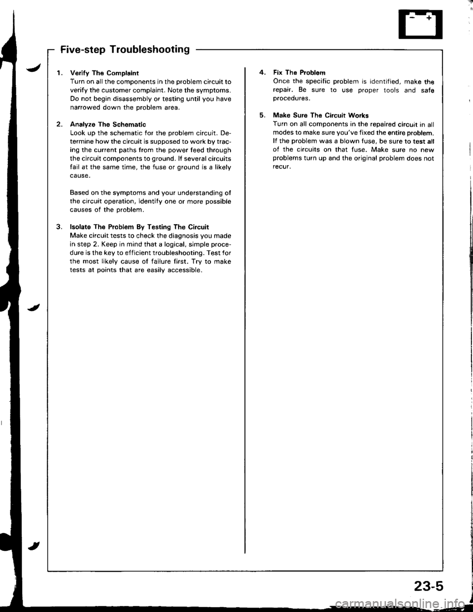
I . Verify The Complaint
Turn on allthe components in the problem circuit to
verify the customer complaint. Note the symptoms.
Do not begin disassembly or testing until you have
narrowed down the problem area.
2- Analyze The Schomatic
Look up the schematic for the problem circuit. De-
termine how the circuit is supposed to work by trac-
ing the current paths from the power feed through
the circuit components to ground. lf several circuits
fail at the same time, the fuse or ground is a likely
Based on the symptoms and your understanding ot
the circuit operation, identity one or more possible
causes of the problem.
3. lsolata The Problem By Testing The Circuit
Make circuit tests to check the diagnosis you made
in step 2. Keep in mind that a logical, simple proce-
dure is the key to efficient troubleshooting. Test for
the most likely cause of failure lirst. Try to make
tests at points that are easilV accessible.
4. Fix The Problem
Once the specific problem is identified, make therepair. Be sure to use proper tools and safep.ocedures.
5. Make Sure The Circuit Workg
Turn on all components in the repaired circuit in allmodes to make sure you've fixed the entire problem.
lf the problem was a blown fuse, be sure to test all
of the circuits on that fuse. Make sure no newproblems turn up and the original problem does not
recuf.
Page 1085 of 1681
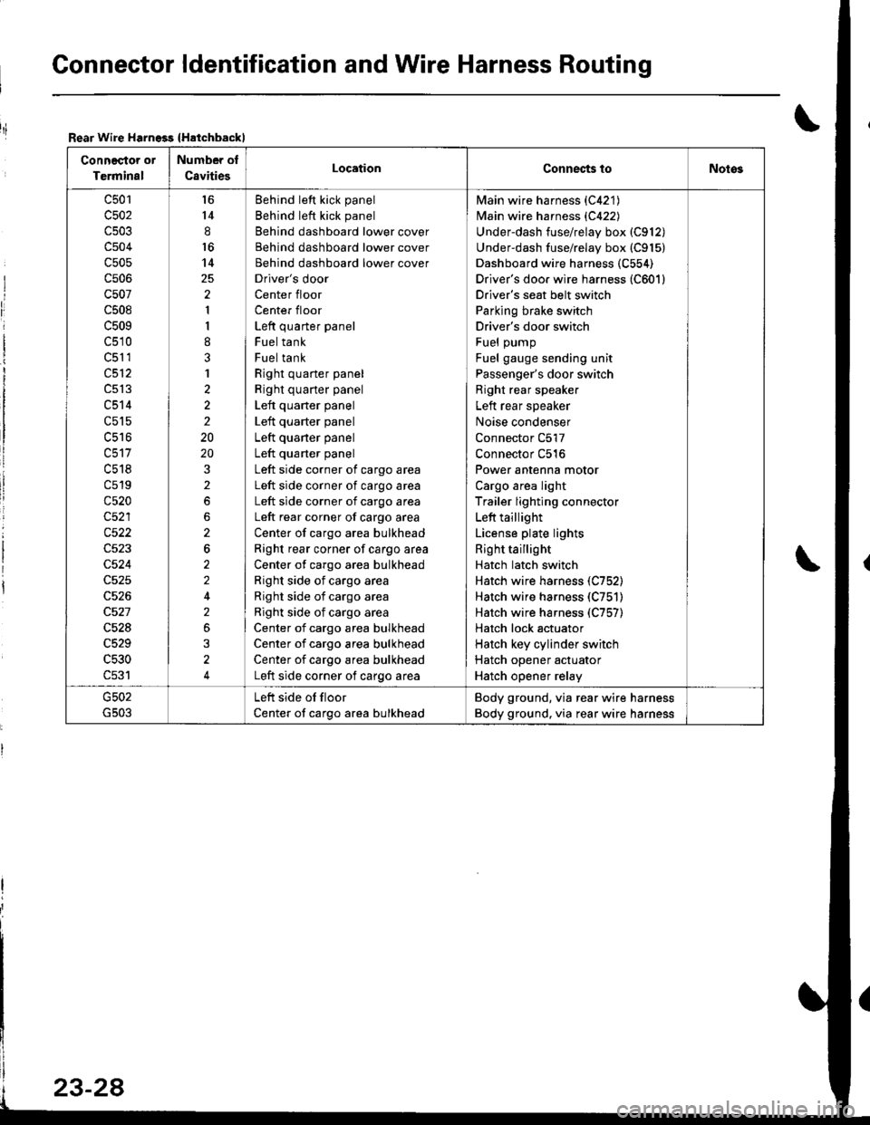
Gonnector ldentification and Wire Harness Routing
Rear Wire Harngss {Hatchbackl
Connector or
Terminal
Number of
C8vitiesLocationConnec{s toNotos
c501
c502
c504
c505
cs06
c507
c508
c509
c510
c51 1
c512
c513
c514
c515
uc to
c518
c519
c520
c522
c524
c528
c529
c530
c531
l6
14
8
16
14
2
1
I
8
3
1
2
2
2
20
20
2
2
6
2
2
2
3
4
Behind left kick panel
Behind left kick panel
Behind dashboard lower cover
Behind dashboard lower cover
Behind dashboard lower cover
Driver's door
Center floor
Center floor
Left quarter panel
Fuel tank
Fuel tank
Right quarter panel
Right quarter panel
Left quarter panel
Left quarter panel
Left quaner panel
Left quarter panel
Left side corner of cargo area
Left side corner of cargo area
Left side corner of cargo area
Left rear corner of cargo area
Center of cargo area bulkhead
Right rear corner of cargo area
Center of cargo area bulkhead
Right side of cargo area
Right side of cargo area
Right side of cargo area
Center of cargo area bulkhead
Center of cargo area bulkhead
Center of cargo area bulkhead
Left side corner of cargo area
Main wire harness {C421)
Main wire harness {C422)
Underdash fuse/relay box (C912)
Underdash fuse/relay box (C915)
Dashboard wire harness (C554)
Driver's doo. wire harness (C601)
Driver's seat belt switch
Parking brake switch
Driver's door switch
Fuel pump
Fuel gauge sending unit
Passenger's door switch
Right rear speaker
Left rear speaker
Noise condenser
Connector C517
Connector C516
Power antenna motor
Cargo area light
Trailer lighting connector
Left taillight
License plate lights
Right taillight
Hatch latch switch
Hatch wire harness (C752)
Hatch wire harness (C751)
Hatch wire harness (C757)
Hatch lock actuator
Hatch key cylinder switch
Hatch opener actuator
Hatch opener relay
Left side of floor
Center of cargo area bulkhead
Body ground, via rear wire harness
Body ground. via rear wire harness
riI
Page 1091 of 1681
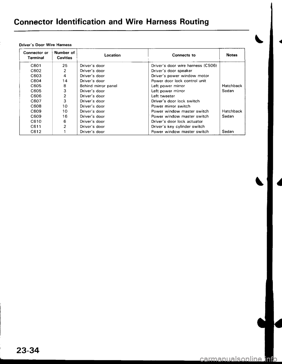
Connector ldentification and Wire Harness Routing
Driver's Door Wire Harness
Connector or
Terminal
Number of
CavitiesLocationConnects toNotgs
c601
c602
c603
c604
c605
c605
c606
c607
c608
c609
c609
c610
c61 1
c612
25
2
4
14
8
3
2
3
10
10
to
6
2,]
Driver's door
Driver's door
Driver's door
Driver's door
Behind mirror panel
Driver's door
Driver's door
Driver's door
Driver's door
Driver's door
Driver's door
Driver's door
Driver's door
Driver's door
Driver's door wire harness (C506i
Driver's door speaker
Driver's power window motor
Power door lock control unit
Left power mirror
Left power mirror
Left tweeter
Driver's door lock switch
Power mirror switch
Power window master switch
Power window master switch
Driver's door lock actuator
Driver's key cylinder switch
Power window master switch
Hatchback
Sedan
Hatchback
Sedan
Sedan
Page 1093 of 1681
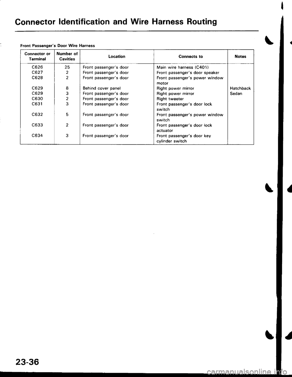
Connector ldentification and Wire Harness Routing
\Front Passengel's Door wire Harness
Connoctot ot
Terminal
Number oI
CavitiesLocationConnects toNotes
c627
c62I
c6 29
c629
c630
c631
c632
c633
c634
25
2
2
8
2
3
5
2
3
Front passenger's door
Front passenger's door
Front passenger's door
Behind cover panel
Front passenger's door
Front passenger's door
Front passenger's door
Front passenger's door
Front passenger's door
Front passenger's door
Main wire harness (C401)
Front passenger's door speaker
Front passenger's power window
motor
Right power mirror
Right power mirror
Right tweeter
Front passenger's door lock
switch
Front passenger's power window
swrrcn
Front passenger's door lock
actuator
Front passenger's door key
cylinder switch
Hatchback
Sedan
Page 1106 of 1681
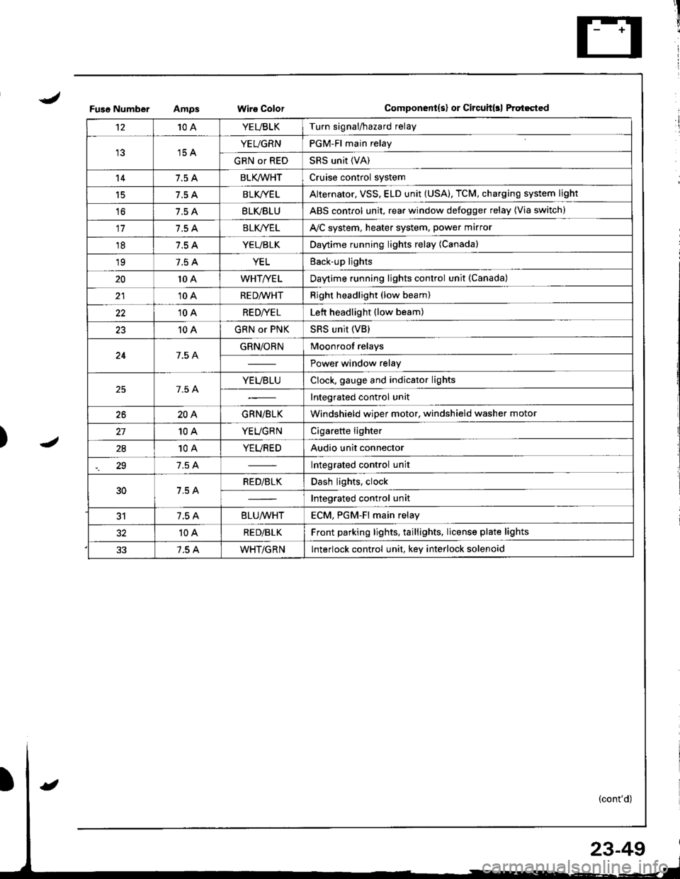
T
I
1
J)
Fuso NumberWire ColorComponent{s} or Circuit(rl ftqt6cted
't210AYEUBLKTurn signal/hazard relay
15 AYEUGRNPGM-Fl main relay
GRN or REDSRS unit (VA)
147.5 ABLK/WHTCruise control system
15BLK/YE LAlternator, VSS, ELD unit (USA), TCM, charging system light
't67.5 ABLVBLUABS control unit, rear window defogger relay (Via switch)
117.5 ABLK//ELAVC system, heater system, power marror
187.5 AYEUBLKDaytime running lights relay (Canada)
197.5 AYELEack-up lights
2010 AWHT/YELDaytime running lights control unit (Canada)
2110 ARED/WHTRight headlight (low beam)
2210 ARE D|YE LLett headlight (low beam)
2310 AGRN or PNKSRS unit (VB)
247.5 AGRN/ORNMoonroof relays
Power window relay
7.5 AYEUBLUClock, gauge and indicator lights
Integrated control unit
2620AGRN/BLKWindshield wiper motor, windshield washer motor
10AYEUGRNCigarette lighter
2810AYEUREDAudio unit connector
29Integrated control unit
30RED/BLKDash lights, clock
Integrated control unit
317.5 A8LU/WHTECM. PGM-Fl main relav
10ARE D/BLKFront parking lights, taillights, license plate lights
7.5 AWHT/GRNInterlock control unit, key interlock solenoid
23-49