transmission HONDA INTEGRA 1998 4.G Repair Manual
[x] Cancel search | Manufacturer: HONDA, Model Year: 1998, Model line: INTEGRA, Model: HONDA INTEGRA 1998 4.GPages: 1681, PDF Size: 54.22 MB
Page 516 of 1681
Pressure Testing
a While testing, be careJulot the rotating front wheels.
a Make sule litts, iacks, and safety stands are placed
properly (see section 1).
CAUTION: Befoie testing, be sure the transmission fluid
is filled to the proper level.
'1. Raise the vehicle {see section 'll.
2. Warm up the engine (the radiator fan comes on),
then stop the engine and connect a tachometer.
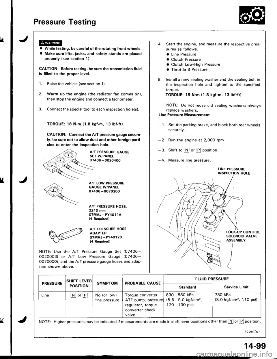
3. Connect the special tool to each inspection hole(s).
TOROUE: 18 N.m l1-8 kgt.m, 13lbf.ftl
CAUTION: Connect the A/T pressure gauge secure-
ly, be sure not to allow dust and olher foreign pani-
cles to enter the inspection hole.
A/T PRESSURE GAUGESET W/PANEL07406 -0020400
A/T LOW PRESSUREGAUGE W/PANEI.07406-OO70300
A/T PRESSURE HOSE,2210 mmOTMAJ _PY4O1 1A{4 Required}
A/T PRESSURE HOSEADAPTER07MAJ -PY40120
l4 Requiredl
NOTE: Use the A/T Pressure Gauge Set (07406-
OO2O0O3) or A/T Low Pressure Gauge (07406-
OOTOOOO), and the A/T pressure gauge hoses and adap-
ters shown above.
4. Start the engine, and measure the respective pres
sures as follows.
a Line Pressure
a Clutch Pressure
a Clutch Low/High Pressure
a Throttle B Pressure
5. Install a new sealing washer and the sealing bolt in
the inspection hole and tighten to the specified
torque.
TOROUE:18 N.m (1.8 kgf.m, 13lbf.ft)
NOTE: Do not reuse old sealing washers; alwaysreplace washers.
Line Pressure Measurement
-1. Set the parking brake, and block both rear wheels
securely.
-2. Run the engine at 2,000 rpm
3. Shift to S or @ position.
4. lMeasure line pressure.
LINE PRESSUREINSPECTION HOLE
LOCK-UP CONTROLSOLENOID VALVEASSEMBLY
PRESSURESHIFT LEVER
POST ONSYMPTOMPROBABLE CAUSEFLUID PRESSURE
StandardService Limit
LineNo,BNo (or low)
Irne pressure
Torque converter,
ATF pump, pressure
regulator, torque
converter check
830 88o kPa
(8.5 9.O kgf/cm'�,
1 20 130 psi)
78O kPa(8.O kgf/cm'�, 1 10 psi)
NOTE: Higher pressures may be indicated if measurements are made in shitt lever positions other than S or f, position.
{cont'd )
14-99
Page 521 of 1681
Transmission
Removal
. Make sure lifts, iacks and salety stands are placed
properly, and hoist brackets are attached to lhe cor-
rect position on the engine (see section 11.
. Apply parking brake and block real wheels, so vehi-
cle will nol roll off stands and fall on you while work-
ing under it.
CAUTION: Use fender covers to avoid damaging paint-
ed surtaces.
1 . Disconnect the battery negative (- ) and positive { + )
cables from the battery.
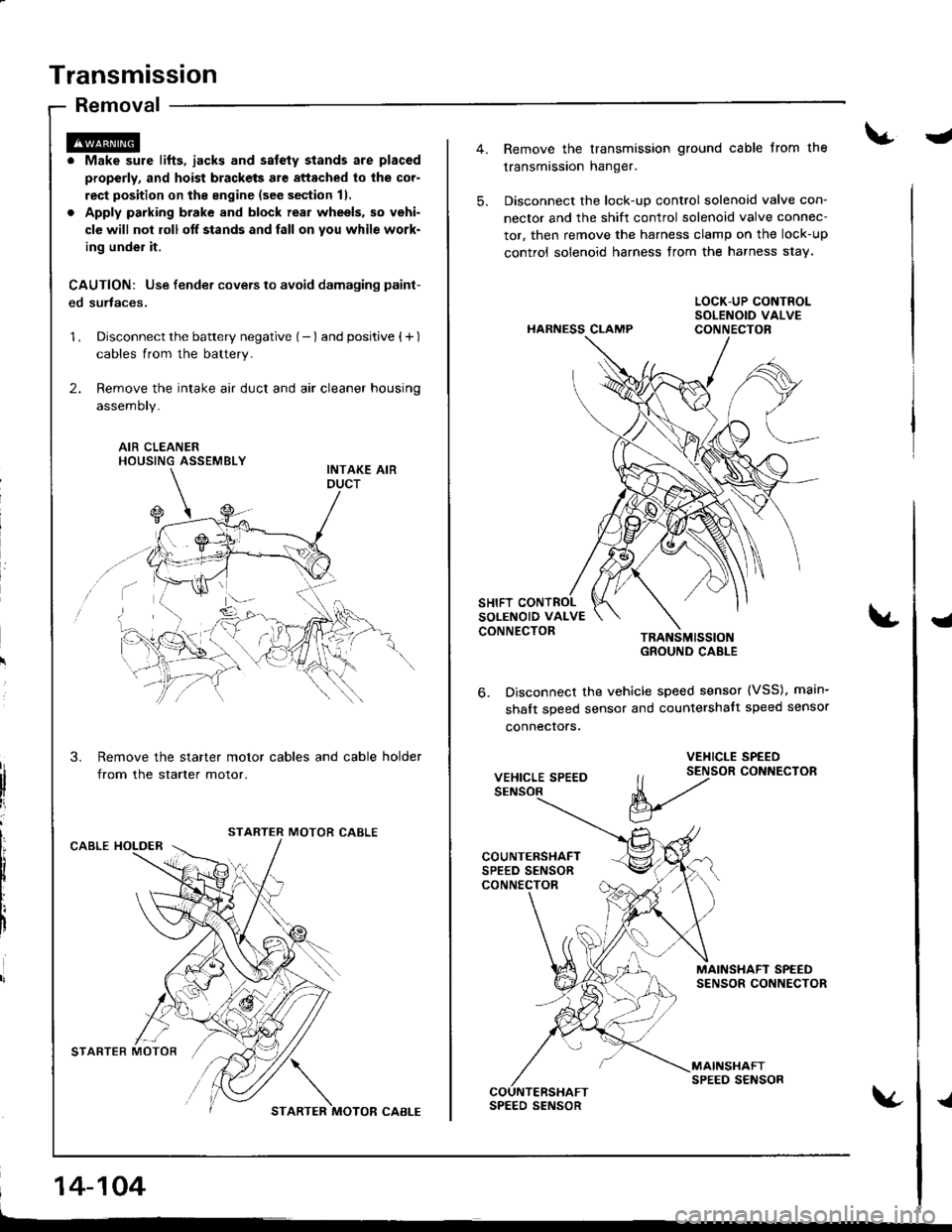
2. Remove the intake air duct and air cleaner housing
assemoty.
AIR CLEANERHOUSING ASSEMBLY
Remove the starter motor cables and cable holder
from the starter motor.
MOTOR CABLECABLE HOLDER
STARTER MOTOR'/,/ \
STARTER MOTOR CABI-E
14-104
-
5.
Remove the transmission ground cable from the
transmission hanger.
Disconnect the lock-up control solenoid valve con-
nector and the shift control solenoid valve connec-
tor, then remove the harness clamp on the lock-up
control solenoid harness from the harness s1ay.
HARNESS CLAMP
TRANSMISSIOIGROUND CABLE
Disconnect the vehicle speed sensor (VSS), main-
shalt speed sensor and countershalt speed sensor
connecrors.
{
6.
VEHICLE SPEED
VEHICLE SPEED
ll t2tor coNNEcroR
V
MAINSHAFT SPEEDSENSOR CONNECTOR
MAINSHAFTSPEED SENSORCOUNTERSHAFTSPEED SENSOR{
Page 522 of 1681
8.
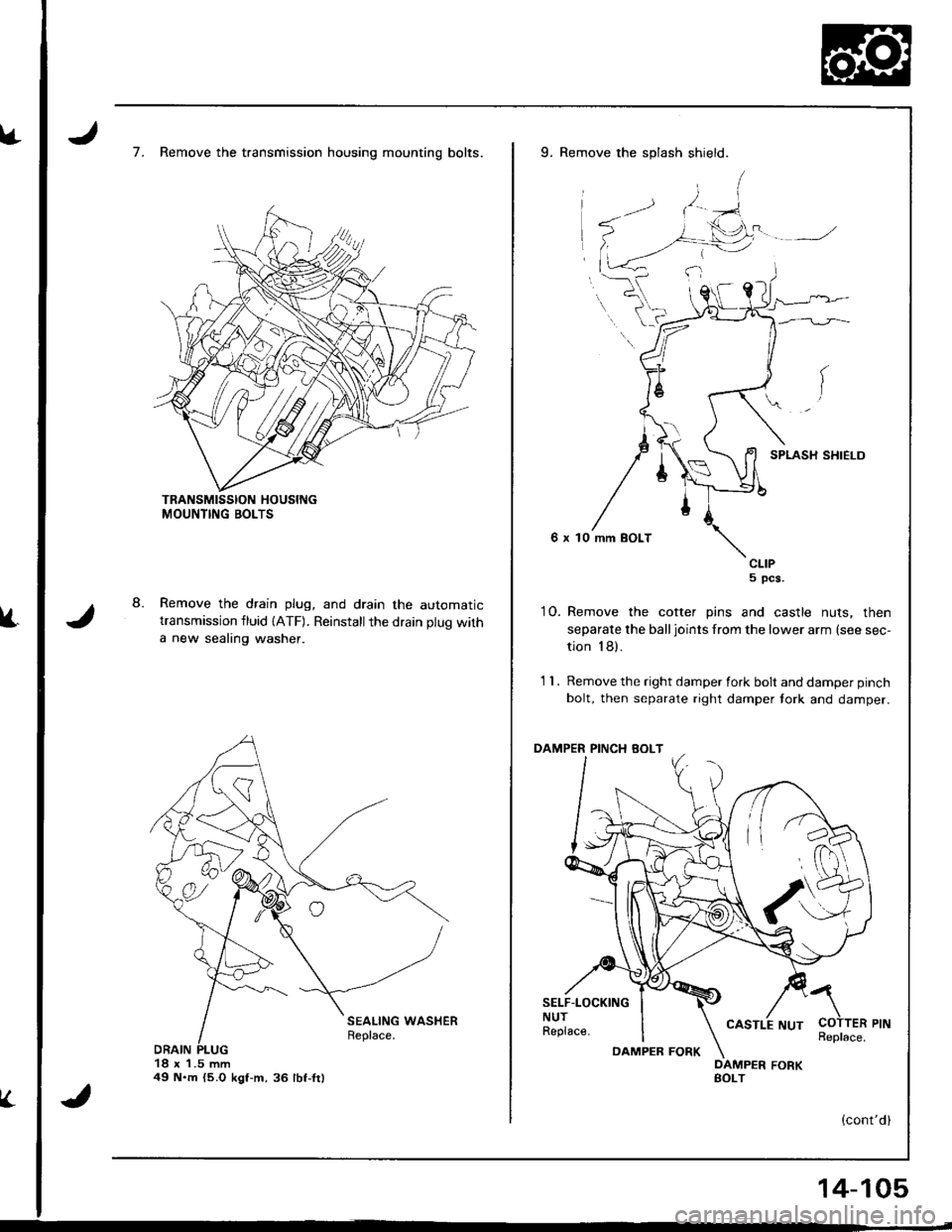
7. Remove the transmission housing mounting bolts.
Remove the drain plug, and drain the automatictransmission fluid {ATF). Reinstallthe drain plug with
a new sealing washer.
18 x 1.5 mm49 N.m {5.O kgt-m,36 lbf-fr)
V.
9. Remove the splash shield.
SPLASH SHIELD
6 x 10 mm BOLT
CLIP5 pcs.
10. Remove the cotter pins and castle nuts, then
separate the balljoints from the lower arm (see sec-
tion 18).
1 1 . Remove the right damper fork bolt and damper pinch
bolt, then separate right damper tork and damper.
PINCH BOLT
SELF.LOCKINGNUTReplace.
a
COTTER PINReplace.DAMPEB FORK
14-105
Page 523 of 1681
Transmission
Removal (cont'd)
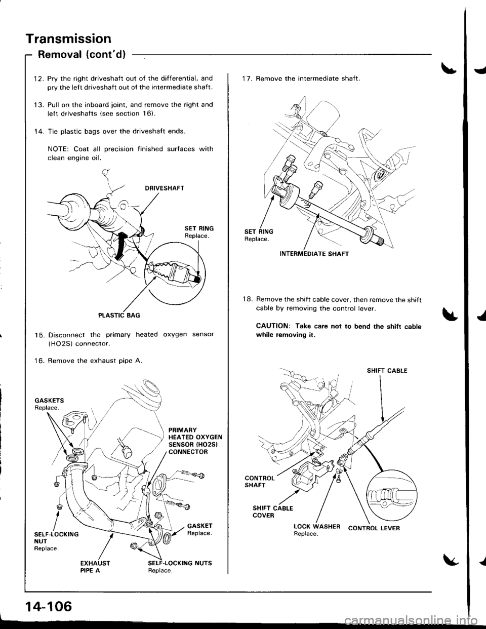
'12. Pry the right driveshaft out of the differential, and
pry the lelt driveshaft out ol the intermediate shaft.
13. Pull on the inboard joint, and remove the right and
lelt driveshatts (see section l6).
14. Tie plastic bags over the driveshalt ends.
NOTE: Coat all precision finished surlaces with
clean engine oil.
Disconnect the primary heated oxygen sensor
(HO2S) connector.
Remove the exhaust pipe A.
| 5.
to.
PRIMARYHEATEO OXYGENSENSOR {HO25lCONNECTOR
SELF-LOCKINGNUTReplace.
14-106
J
J
.l
18.
'17. Remove the intermediate shaft.
Remove the shitt cable cover, then remove the shilt
cable by removing the control lever.
CAUTION: Take care not to bend the shifr cablewhile removing it.
CONTROL LEVER
INTERMEDIATE SHAFT
SHIFT CABLE
Page 524 of 1681
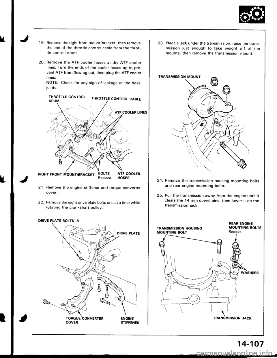
u19.Remove the right front mount/bracket, then remove
the end of the throltle control cable from the throt-
tle control drum.
Remove the ATF cooler hoses at the ATF cooler
lines. Turn the ends of the cooler hoses up to pre-
vent ATF from flowing out, then plug the ATF cooler
lines.
NOTE: Check for any sign ol leakage at the hosejornrs.
THROTTLE CONTROL CABLE
20.
f
RIGHT FRONT MOUNT/BRACKET
21. Remove the engine stiftener and torque converter
cover,
22. Remove the eight drive plate bolts one at a time whilerotating the crankshaft pulley.
EOLTS ATF COOLERReplace. HOSES
ENGINESTIFFENERCOVERTRA
14-107
23. Place a jack under the transmission. raise the trans-mission just enough to take weight off of the
mounts, then remove the transmtssion mount.
TRANSMISSION MOUNT
24. Remove the transmission housing mounting bolts
and rear engine mounting bolts.
25. Pull the transmission away trom the engine until itclears the 14 mm dowel pins, then lower it on thetransmission jack.
REAR ENGINEMOUNTING BOLTSReplace.
WASHERS
MISSION JACK\NS
Page 525 of 1681
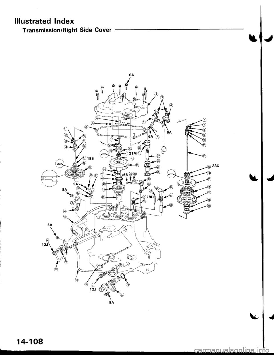
lllustrated lndex
Transmission/Right Side Cover
6A
12J
3
lt
14-108
J
Page 527 of 1681
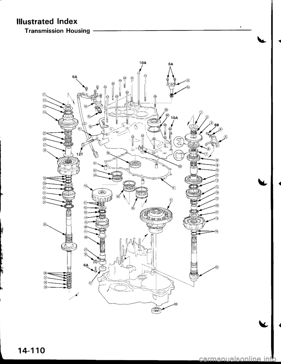
lllustrated Index
Transmission Housing
" ui','..':!(.:=''...
14-110
Page 528 of 1681
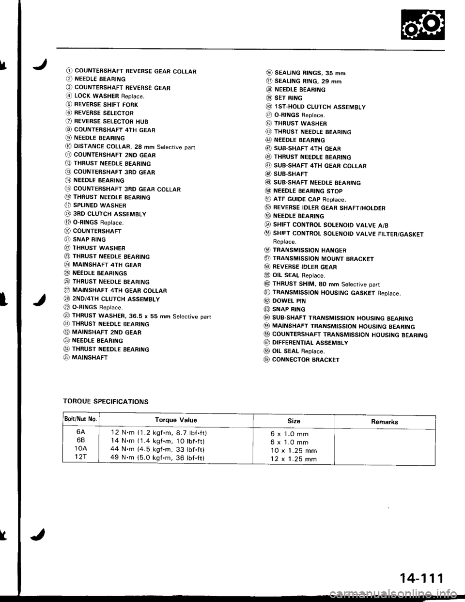
fO) COUNTERSHAFT REVERSE GEAR COLLAR(, NEEDLE BEARING
@ couNTERSHAFT REVEBsE GEAR(4 LOCK waSHER Replace.
G) REVERSE sHtFr FoRK
G) REVERSE SELECTOR
O REVERSE SELEcToR HUB
@ coUNTERSHAFT 4TH GEAR
O NEEDLE BEARING
tE DISTANCE COLLAR, 28 mm Setective part(} COUNTERSHAFT 2ND GEAR
[, THBUST NEEDLE BEARING
@ coUNTERSHAFT 3RD GEAR
[E NEEDI.E BEARING(' COUNTERSHAFT 3RD GEAR COLLAR
@ THRUST NEEDLE BEARING(, SPLINED WASHER
@ 3RD cLUTcH ASSEMBLY
t0 O-RINGS Replace.
@ couNTERSHAFT(?]) SNAP RING
@ THRUST WASHER
@ THRUST NEEDLE BEARING
Q} MAINSHAFT 4TH GEAR
@ NEEDLE BEARINGS
@ THRUST NEEDLE BEARING
@ MAINSHAFT 4TH GEAR coLLAR
€O 2ND/4TH cLUTcH ASSEMBLY
@ O-RINGS Reptace.
@ THRUST WASHER.36.S x 55 mm Setective part
C]) THRUST NEEoLE BEARING
@ MAINSHAFT 2ND GEAR
@ NEEDLE BEARING
0t THRUST NEEDLE BEARTNG
@ MAINSHAFT
@ SEALTNG RtNGs, 35 mm
€D SEAL|NG R|NG. 29 mm
@ NEEDLE B€ARING
@ sET RING
@ lsT.HoLD cLUTCH ASSEMBLY
@ o-RtNGs Reptace.
(, THRUST WASHER
@ THRUST NEEDLE BEARING
@ NEEDLE BEARING
@ SUB-SHAFT 4TH GEAR(O THRUST NEEDLE BEARING
@ sUB-SHAFT 4TH GEAR coLLAR
@ SUB-SHAFT
@ SUB-SHAFT NEEDLE EEARING
@ NEEDLE BEARTNG sToP
@ ATF GUTDE cAp Reptace.
@ REVERSE IDLER GEAR sHAFT/HoLDER
@ NEEDLE BEARING
(i) sHrFT coNTRoL soLENotD vALvE A/B
@ sHrFT coNTRoL soLENotD vALVE FTLTER/GASKETReplace.
@ TRANSMISSIoN HANGER
.5, TRANSMISSIoN MoUNT BRACKET
@) REVERSE TDLER GEAR
@ otL SEAL Replace.
@ THRUST SHIM, SO mm Setective part
@ TRANSMTSSTON HOUSTNG GASKET Reptace.
@ DowEL PtN
@ SNAP RING
@ SUB-SHAFT TRANSMlsstoN HoustNG BEARTNG
@ MA|NSHAFT TRANsMtssroN HoustNG BEARTNG
@ CoUNTERSHAFT TRANSMIssloN HoUsING BEARING
@ DIFFERENTIAL ASSEMBLY
@ oll- SEAL Replace.
E9 CONNECTOR BRACKET
TOROUE SPECIFICATIONS
I
Bolt/Nur No.Torque ValueSizeRemarks
6A
6B
10A
12r
'12 N.m {1.2 kgf.m, 8.7 tbf.ft)14 N.m (1.4 kgl.m, 1O tbf.ft)44 N.m {4.5 kgf 'm, 33 tbf .ft}
49 N.m (5.O kgf.m, 36 lbf.tt)
6 x 1.O mm
6 x 1.0 mm
10 x 1.25 mm
12x1.25mm
14-111
Page 531 of 1681
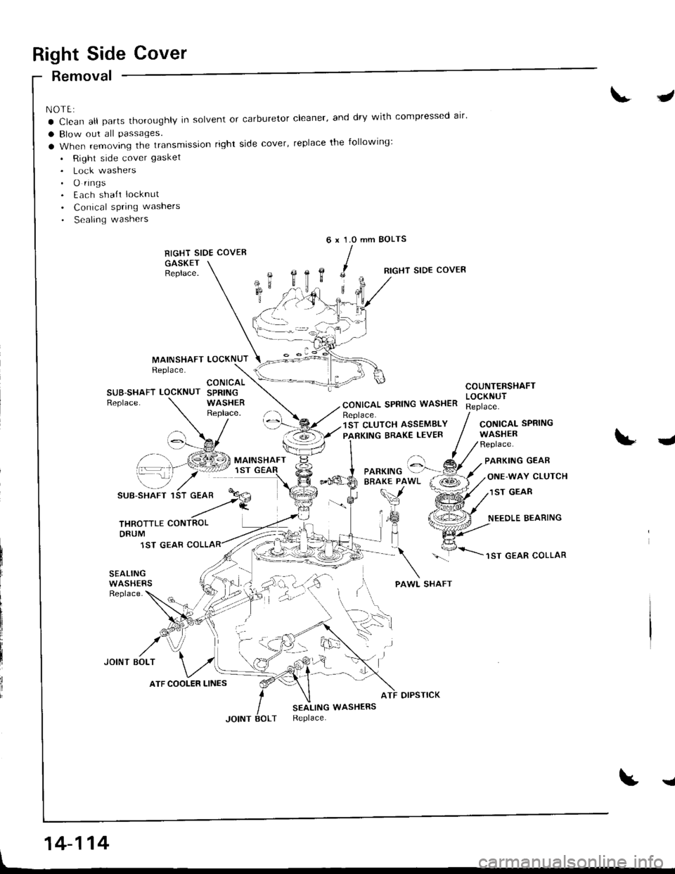
Right Side Cover
Removal
NOTE:
a Clean all parts thoroughly in solvent or carburetor cleaner' and dry with compressed alr'
a Blow out all Passages.
a When removing the transmission right side cover, replace the following:
. Right side cover gasket
. Lock washers. O rings. Each sha{t locknut
. Conical spring washers
. Sealing washers
RIGHT SIDE COVER
GASKETBeplace.
J
mm BOLTS6x1.0
,c
B,
MAINSHAFTReplace.LOCKNUT
RIGHT SIDE COVER
CONICAL SPRING WASHER
COUNTERSHAFTLOCKNUTSUB-SHAFT LOCKNUTReplace.
CONICALSPRINGWASHERReplace.Replace.1ST CLUTCH ASSEMBLY
PARKING BRAKE LEVERCONICALWASHERReplace.
SPRING
J
\-_7
SUB-SHAFT 1
PARKING GEAR
ONE-WAY CLUTCH
1ST GEAR
NEEOLE BEARING
1ST GEAR COLLAR
SEALINGWASHERSReplace.
JOINT BOLT
otPsTtcK
SEALING WASHERSReplace.
t
'::-Pf.a
THROTTLE CONTROLDRUM
1ST GEAB
ATF COOLER LINES
'. .)
14-114
I
Page 532 of 1681
I
t
I
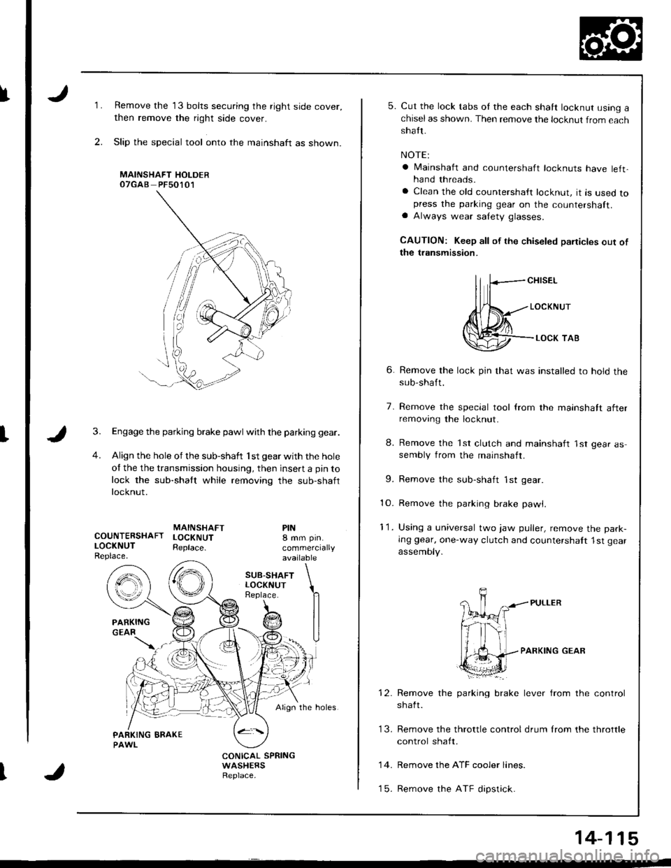
1.
2.
Remove the 13 bolts securing the right side cover,
then remove the right side cover.
Slip the special tool onto the mainshaft as shown.
MAINSHAFT HOLDEROTGAB PFsO1O1
Engage the parking brake pawl with the parking gear.
Align the hole of the sub-shaft 'lst gear with the hole
of the the transmission housing, then insert a pin to
lock the sub-shaft while removing the sub-shaft
locknut.
MAINSHAFTCOUNTERSHAFT LOCKNUTLOCKNUT Reptace.Replace.
PIN8 mm pin.
commerciallyavailable
SUB.SHAFTLOCKNUTReplace.
Align the holes.
CONICAL SPRINGWASHERSReplace.
5. Cut the lock tabs oI the each shaft locknut using achiselas shown. Then remove the locknut from eachshatt.
NOTE:
a lvlainshaft and countershaft locknuts have left,hand threads.
a Clean the old countershaft locknut, it is used topress the parking gear on the countershaft.a Always wear salety glasses.
CAUTION: Keep all of the chiseled paiticles out ofthe transmission.
ll fcH,sEL
Jl{*---,o"*",r
@--.**,o,
6. Remove the lock pin that was installed to hold thesub-shaft.
7. Remove the special tool from the mainshatt afterremoving the locknut.
8. Remove the 'lst clutch and mainshaft 'lst gear assembly from the mainshaft.
9. Remove the sub-shaft 1st gear
10. Remove the parking brake pawl,
11. Using a universal two jaw puller, remove the park-
Ing gear, one-way clutch and countershalt 1st gear
assemoty.
PARKING GEAR
brake lever from the controlRemove the parking
shaft.
Remove the ATF cooler lines.
Remove the ATF dipstick.
13. Remove the throttle control drum lrom the throttle
control shaft.
14.
t5.
14-115