Ground location HONDA INTEGRA 1998 4.G Workshop Manual
[x] Cancel search | Manufacturer: HONDA, Model Year: 1998, Model line: INTEGRA, Model: HONDA INTEGRA 1998 4.GPages: 1681, PDF Size: 54.22 MB
Page 465 of 1681
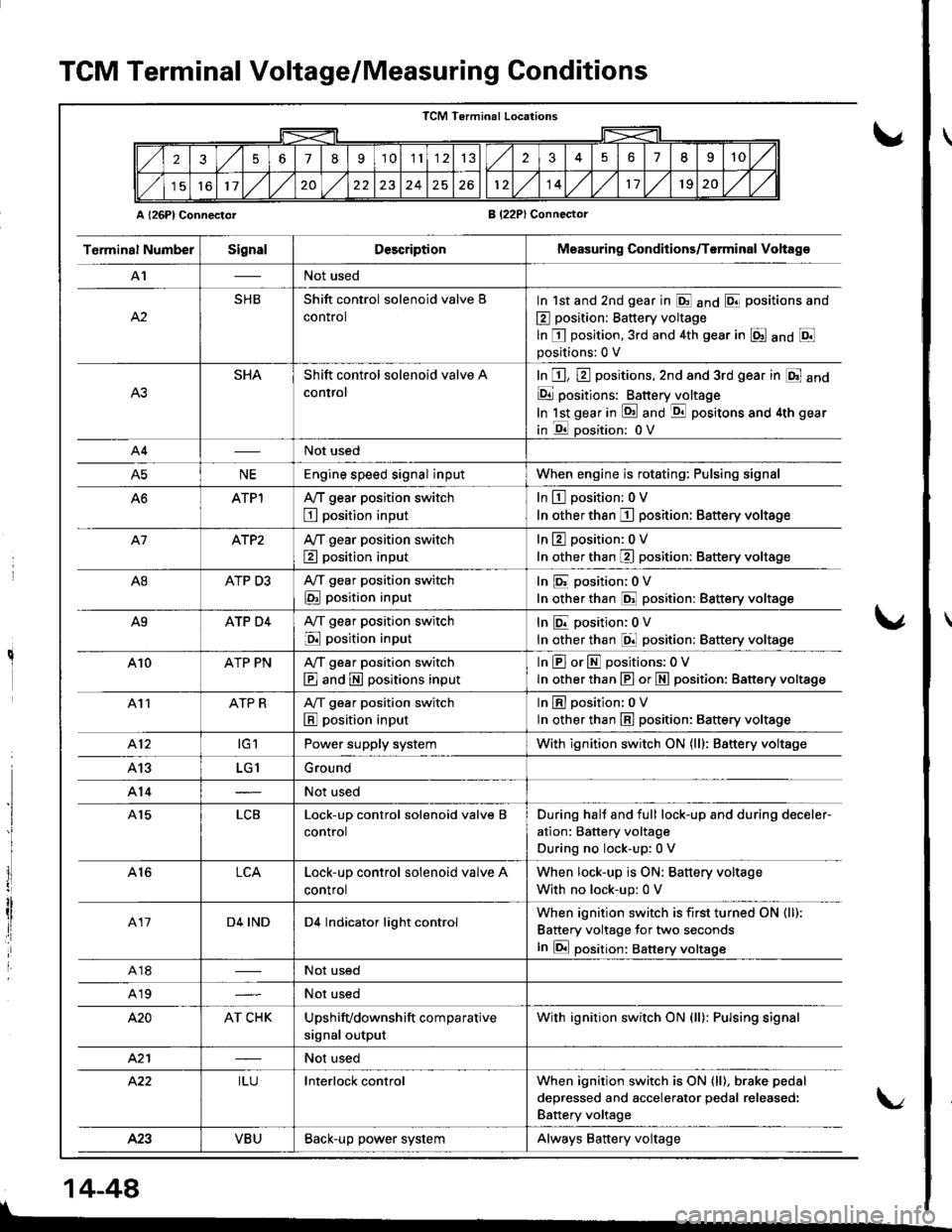
TCM Terminal Voltage/Measuring Conditions
A l26Pl ConnectorB (22PlConnector
TCM Terminal Locations
256789'1011132351II10
11,/l/2024261214,/l/1120,/1,/
T6rminal NumberSignalDescriptionMeasuring Conditions/T€rminal Voltag€
A'INot used
A2
SHBShift control solenoid valve B
control
In 1st and 2nd gear in E anO E positions and
E position: Battery voltage
ln E position,3rd and 4th gear in E anO Epositions:0 V
SHAShift control solenoid valve A
control
In E, E positions,2nd and 3rd gear in E and
E positions: Batteryjloltage
In lst gear in !d and -qtl positons and 4th gear
in E oosition: 0V
A4Not used
A5NEEngine speed signal inputWhen engine is rotating: Pulsing signal
ATPlA,/T gear position switch
E position input
In L!-l position: 0 V
In other than I position: Battery voltage
A7ATP2Ay'T gear position switch
E position input
In 13 position:0 V
In other than E position: Battery voltage
A8ATP D3A,/T gear position switch
E position input
In E position:0V
In other than @ position: Battery voltage
A9ATP D4A,/T gear position switch
E position input
InEposition;0V
In other than El position: Battery voltage
410ATP PNA,/T gear position switch
E and E positions input
InEorEpositions:OV
In other than E or N position: Battery vottage
411ATP RA/T gear position switch
E position input
lnEposition: oV
ln other than E position: 8attery voltage
412tGlPower supply systemWith ignition switch ON (lll: Battery voltage
413LG1Ground
A14Not used
A15LCBLock-up control solenoid valve B
control
During hall and full lock-up and during deceler-
ation: Battery voltage
During no lock-up:0 V
A16LCALock-up control solenoid valve A
control
When lock-up is ON; Battery voltage
With no lock-up: 0 V
417D4 INDD4 Indicator light controlWhen ignition switch is first turned ON (ll):
Battery voltage for two seconds
In E position: Battery voltsge
A18Not used
A19Not used
420AT CHKUpshifvdownshift comparative
signal output
With ignition switch ON (ll): Pulsing signal
421Not used
422ILUInterlock controlWhen ignition switch is ON (ll), brake pedal
deoressed and accelerator oedal released:
Battery voltage
423VBUBack-up power systemAlways Battery voltage
I
lI
I
14-44
\/
Page 717 of 1681
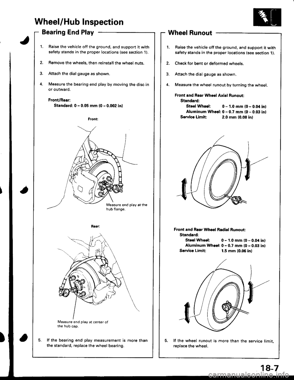
Wheel/Hub Inspection
Bearing End Play
Raise the vehicle off the ground, and support it with
safety stands in the proper locations (see saction 1).
Remove the wheels, then reinstallthe whe6l nuts.
Attach the dial gauge as shown.
Measure the bearing end play by moving the disc in
or outward.
Front/Rear:
Standa.d: 0 - 0.05 mm (0 - 0.qr2 in)
a
Measure end play at center ofthe hub cap.
lf the bearing end play measurement is
the standard, replace the wheel bearing.
Wheel Runout
Raise the vehicle off the ground, and support it withsatety stands in the proper locations (see section 1).
Check for bent or deformed wheels.
Attach the dial gauge as shown.
Measure the wheel runout by turning the wheel.
Front and Roar Whool Axial Runout:
Standard:
Stcsl Whoel: 0 - 1.0 mm (0 - 0.04 inl
Aluminum Whcel: 0 - 0.7 mm (0 - 0.03 inl
Sorvlc. Limit:2.0 mm (0.08 inl
Front End Roar Whod Rldisl Runouti
Standard:
Ste.l Whool: 0 - 1.0 mm (0 - 0.04 inlAluminum Wh.el: 0 - 0.7 mm (0 - 0.03 inl
Sorvico Limit:1.5 mm (0.06 inl
lf the wh€el runout is more than the service limit,
reDlace the wheel.
more than
18-7
Page 731 of 1681
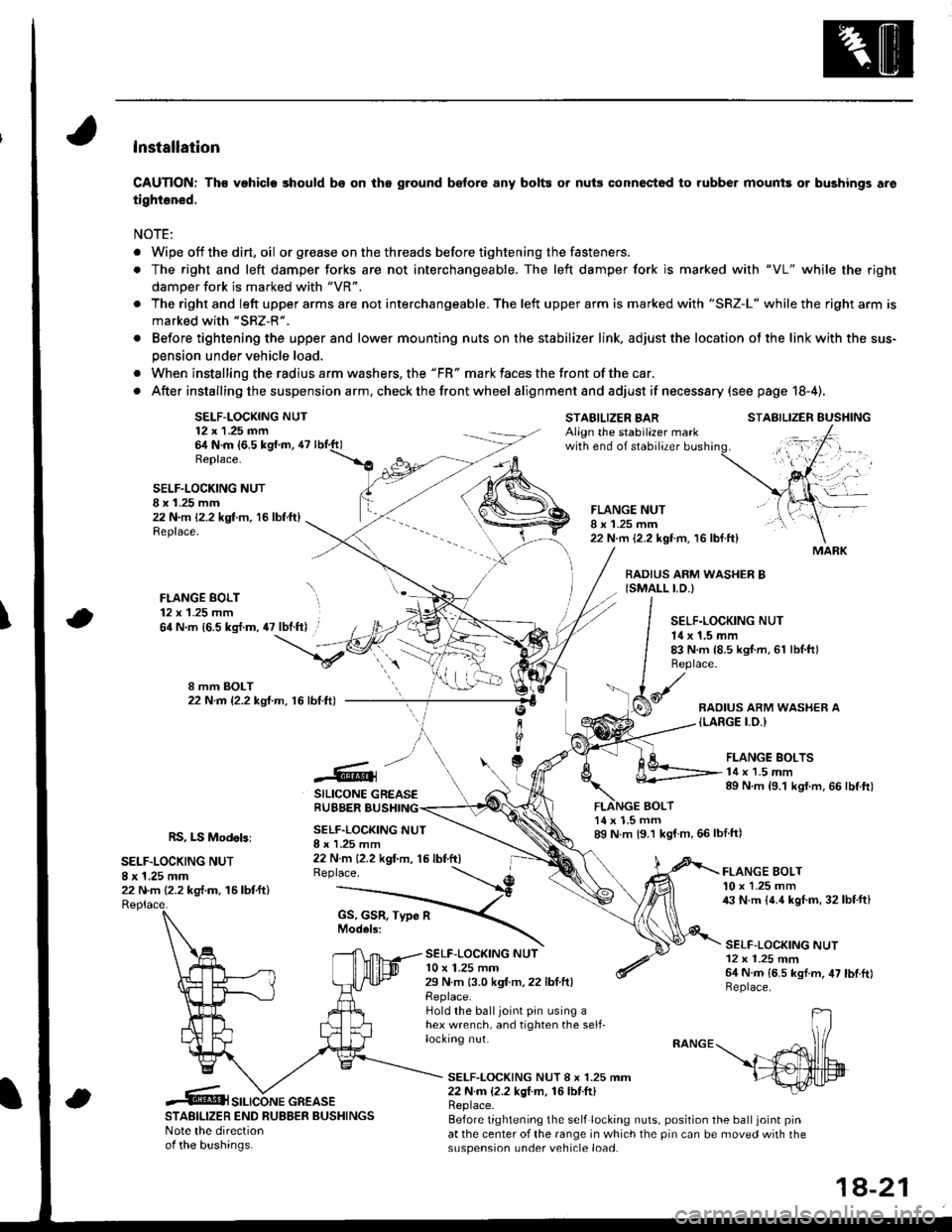
lnstallation
CAUTION: Th€ vehiclo should bs on the ground b€fore any bolts or nuis connectod to rubber mounis or bushings aro
tightened.
NOTE:
. Wipe off thedirt,oil or gr€ase on the threads before tightening the fasteners.
. The right and left damper forks are not interchangeable. The left damper fork is ma.ked with "VL" while the righr
damoer fork is marked with "VR".
. The right and left upper arms are not interchangeable. The left upper arm is marked with "SRZ-L" while the right arm is
marked with "SRZ-R".
. Before tightening the upper and lower mounting nuts on the stabilizer link, adjust the location ot the link with the sus-
pension under vehicle load.
. When installing the radius arm washers, the "FR" mark faces the front ofthe car.
. After installing the suspension a rm, check the front wheel alignmentand adjust if necesssry (see page 18-4).
SELF-LOCKING NUT12 x 1.25 nn64 N.m {6,5 kg{.m, 47Replace.
STABILIZER BARAlign the stabilazer markwith end of stabilizer
BOLT
STABILIZER EUSHING
SELF.LOCKING NUTI x 1.25 mm22 N.m 12.2 kgt m, 16 lbf.ft)Replace.
FLANGE BOLT12 x 1.25 mm
FLANGE NUTI x 1.25 mm22 N.m {2.2 kgt m. 16 lbf.ft}
BADIUS ARM WASHER B{SMALL I.D.)
\64 N.m {6.5 kg{.m, 47 lbt.ft) .SELF.LOCKING NUT14 x 1.5 mm83 N.m {8.5 kgI.m, 61 lbl.ftlReplace.
RAOIUS ARM WASHER A{LARGE I.O.I
.@]
SILICONE GREASERUBBER BUSHING
FLANGE BOLTS14 x 1.5 mm89 N.m {9.1 kgf.m, 66 lbtft)
RS, LS Modebi
SELF.LOCKING NUT8 x 1.25 mm22 N.m (2.2 kg,f.m. 16lbtftl
SELF.LOCKING NUTI x I .25 mm22 N m {2.2 kgt'm, 15 lbf.ft)Replace.
14 x 1.5 mm89 N m {9.1 kgf m,66lblft)
SELF-LOC(ING NUTl0 x 1.25 mm29 N.m 13.0 kgf.m,22 lbtftlReplace.Hold the balljoint pin using ahex wrench, and tighten the self-locking nut.
FLANGE BOLT10 x 1.25 mm43 N.m {4.4 kgl.m, 32lbf.ft}
SELF-LOCKING NUT12 x 1.25 mm64 N.m {6.5 kgf.m, 47 lbtftlReplace.
SELF-LOCKING NUT 8 x 1.25 mm22 N.m {2.2 kgI m, 16lbf.ft)
STABILIZER END RUBBER BUSHINGSNote the directionof the bushinas.
Replace.Before tightening the self locking nuts, position the ball joint pinat the center of the range in which the pin can be moved with thesuspension under vehicle load.
MARK
SILICONE GREASE
1A-21
Page 775 of 1681
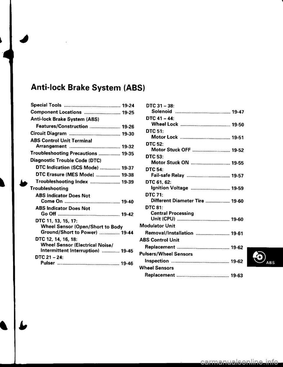
Anti-lock Brake System {ABS}
Speciaf Tools ............... 19-24
Component Locations,...........,..,........... 19-25
Anti-lock Brake System (ABSI
Features/Construction ....................... 19-2G
Circuit Diagram ........... 19-30
ABS Control Unit Terminal
Arrangement ........... 19-32
Troubleshooting Precautions ................ 1g-35
Diagnostic Trouble Code (DTC)
DTC Indication (SCS Mode) ............... t9-37
DTC Erasure {MES Mode) .................. 19-38
b Troubleshooting Index ...................... 19-39- Troubleshooting
ABS Indicator Does Not
Come On .............. 19-40
ABS Indicator Does Not
Go Off .............. ..... 19-42
DTC 11, 13, 15. 17:
Wheel Sensor (Open/Short to Body
Ground/Short to Power) ............... l9-44
DTC 12. 14, 16, 18:
Wheel Sensor (Electrical Noise/
Intermittent Interruption) ..........,.. 19-45
DTC21 -24:
Pulser ...,.......... ..... 19-46
DTC 31 - 38:
Solenoid .............. 19-47
DTC 41 - 44:
Wheel Lock .......... 19-50
DTC 51:
Motor Lock .......... 19-51
DTC 52:
Motor Stuck OFF ...................,........ 19-52
DTC 53:
Motor Stuck ON ............................. 19-55
DTC 54:
Fail-safe Relay ................................ t9-57
DTC 61.62:
lgnition Voltage ............................. 19-59
DTC 71:
Different Diameter Tire .................. 1 9-60
DTC 81:
Gentral Processing
Unit {CPU} ............ 19-60
Modulator Unit
Bemoval/lnstallation ......................... 19-61
ABS Control Unit
Replacement ............ 19-62
Pulsers/Wheel Sensors
Inspection ................ 19-62
Wheel Sensors
Replacement .,.......... 19-63
Page 1070 of 1681
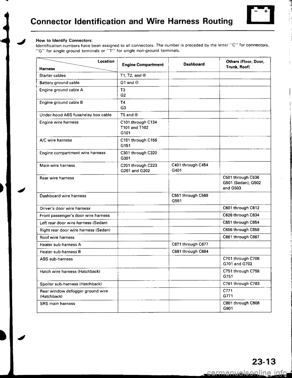
Connector ldentification and Wire Harness Routing
JHow to ldenti{v Connectors:
ldentification numbers have been assigned to all connectors. The number is preceded by the letter "C" for connectors,"G" for single ground terminals ot "f" lor single non-ground terminals.
/
Location
HarnossEngine CompartmentDashboardOthers (Floor, Door,
Trunk. Rooll
Starter cablesT1, T2, and @
Battery ground cableG1 and O
Engine ground cable A
G2
Engine ground cable BT4
G3
Under-hood ABS fuse/relav box cableT5 and @
Engine wire harnessC101 through C134
T101 and T102
G101
A,/C wire harnessC151 through C156
G151
Engine compartment wire harnessC301 through C320
G301
Main wire harnessC201 through C223
G20'l and G202
C40l through C454
G401
Rear wire harnessC501 through C536
G501 (Sedan), G502
and G503
Dashboard wire harnessC551 through C569
G551
Driver's door wire harnessC601 through C612
Front passenger's door wire harnessC626 through C634
Left rear door wire harness (Sedan)C65l through C654
Right rear door wire harness (SedanlC656 throughc659
Roof wire harnessC661 through C667
Heater sub-harness AC671 through C677
Heater sub-harness BC68l through C684
ABS sub-harnessC701 through C706
G701 and G702
Hatch wire harness (Hatchback)C751 through C758
Spoiler sub-harness {Hatchback)C761 through C763
Rear window defogger ground wire
(Hatchback)
c11 l
G77'l
SRS main harnessC801 through C808
G801
23-13
Page 1071 of 1681
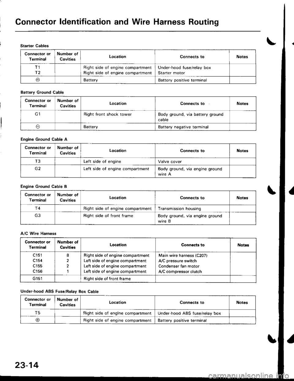
Connector ldentification and Wire Harness Routing
Starter Cables
Connectol ot
Terminal
Numbel of
CavitiesLocationConnects toNotes
Tl
r2
Right side of engine compartment
Right side oI engine compartment
Under-hood Iuse/relay box
Starter motor
oBatteryBattery positive terminal
Battely Ground Cable
Connector ol
Terminal
Numbel of
CavitiesLocationConnects toNotes
Right lront shock towerBody ground, via battery ground
caore
oBatteryBattery negative terminal
Engine Ground Cable A
Connector ol
Terminal
Number ol
CavitiesLocationConnects toNotes
T3Left side of engineValve cover
c2Left side oI engine compartmentBody ground. via engine ground
Engine Ground Cable B
Connector ol
Terminal
Numbel of
CavitiesLocationConnects toNot€s
r4Right side of engine compartmentTransmission housing
Right side of front frameBody ground, via engine ground
wire B
A/C Wire Harness
Connector or
Terminal
Number of
CavitiesLocationConnects toNotos
c 151
cl54
c156
8
2,l
Righr side of engine compartment
Left side of engine companment
Left side of engine compartment
Left side of engine compartment
Main wire harness (C207)
A,/C pressure switch
Condenser fan motor
ly'C compressor clutch
Right side of front frame
Under-hood ABS Fuse/Relav Box Cable
Connector or
Telminal
Number of
CavitiesLocationConnects toNotes
T5Right side o'f engine compartmentUnderhood ABS fuse/relay box
@Right side oI engine compaftmentBattery positive terminal
23-14
Page 1073 of 1681
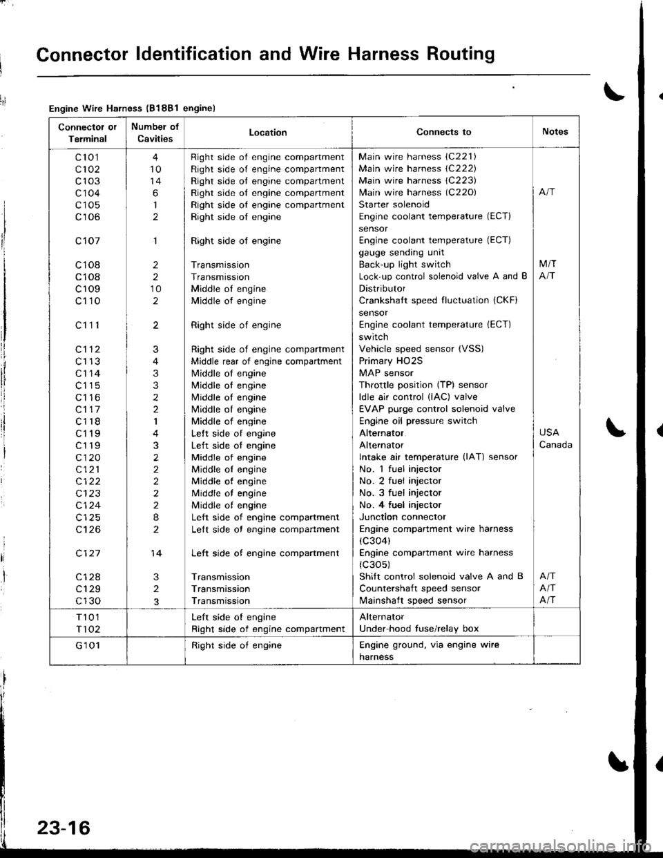
Connector ldentification and Wire Harness Routing
Connectot or
Terminal
Numbel of
CavitiesLocationConnects toNotes
c'to 1
c102
c103
c'1 04
c105
c106
c 107
c108
c108
c109
c110
c112
c113
c'r 14
c115
c116
c117
c118
ct'l9
c119
c120
c121
c122
c124
c't 26
c127
c128
c129
c130
c111
4
10
14
6
I
1
2
2
10
2
3
2
J
4
3
3
2
2
I
3
2
2
2
2
2
I
2
14
Right side of engine compartment
Right side of engine compartment
Right side ot engine compartment
Right side of engine compartment
Right side oI engine compartment
Right side of engine
Right side of engine
Transmission
Transmission
Middle ot engine
Middle ot engine
Right side of engine
Right side of engine compartment
Middle rear of engine compartment
N4iddle of engine
N4iddle ol engine
Middle oI engine
Nliddle ot engine
Middle of engine
Lelt side of engine
Left side of engine
Middle of engine
Middle oI engine
Middle of engine
Middle of engine
Middle ot engine
Left side of engine compartment
Lelt side ot engine compartment
Left side of engine compartment
Transmission
Transmission
Transmission
Main wire harness (C221)
Main wire harness (C222)
Main wire harness 1C223)
lvlain wire harness (C220)
Starter solenoid
Engine coolant temperature (ECT)
sensor
Engine coolant temperature (ECT)
gauge sending unit
Back-up light switch
Lock-up control solenoid valve A and B
Distributor
Crankshatt speed fluctuation (CKF)
sensor
Engine coolant temperature (ECT)
switch
Vehicle speed sensor (VSS)
Primary HO2S
MAP sensor
Throttle position (TP) sensor
ldle air control (lAC) valve
EVAP purge control solenoid valve
Engine oil pressure switch
Alternator
Alternator
lntake air temperature (lAT) sensor
No. 1 fuel injector
No. 2 fuel injector
No. 3 fuel injector
No. 4 fu€l injector
Junction connector
Engine compartment wire harness
(c304)
Engine compartment wire harness
(c30s)
Shift control solenoid valve A and B
Countershaft speed sensor
lvlainshaft speed sensor
M/T
NT
USA
Canada
Afi
Afi
T101
T102
Left side oI engine
Right side of engine compartment
Alternator
Under hood fuse/relay box
G'1 01Right side oI engineEngine ground. via engine wire
harness
Engine Wire Harness (B188l enginel
23-16
Page 1075 of 1681
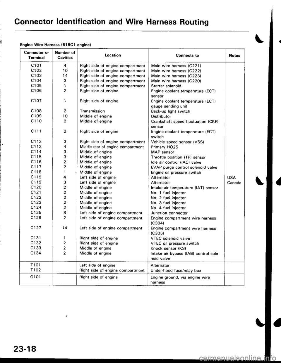
Connector ldentification and Wire Harness Routing
Engine Wire Harness (B18Cl enginel
Connectol ol
Terminal
Number of
CavitiesLocationConnects toNotes
c 101
c102
c103
c104
c105
c106
c101
c108
cr09
c110
c'r 11
cl12
c1't3
c114
c115
c116
cl17
c118
c119
c119
c120
cI2'l
cl24
c126
c127
cl31
c132
c133
c134
10
14
3
1
2
1
2
10
2
'I
3
2
2
2
I
1
2
2
?
3
2
14
Right side of engine compartment
Right side of engine compartment
Right side of engine compartment
Right side ol engine compartment
Right side of engine compartment
Righr side oI engine
Right side of engine
Transmission
Middle of engine
Middle of engine
Right side of engine
Right side of engine compartment
Middle rear of engine compartment
Middle of engine
Middle of engine
Middle of engine
Middle of engine
i/iddle of engine
Left side ot engine
Lelt side ot engine
Middle ot engine
Middle of engine
Middle of engine
Middle of engine
Middle of engine
Left side of engine companment
Left side of engine compartment
Lelt side of engine compartment
Right side of engine
Right side of engine
Middle of engine
Middle of engine
lvlain wire harness (C221 )
Main wire harness {C222)
Main wire harness (C223)
Main wire harness (C220)
Starter solenoid
Engine coolant temperature (ECT)
sensor
Engine coolant temperature (ECT)
gauge sending unit
Back-up light switch
Distributor
Crankshalt speed fluctuation (CKFI
sensor
Engine coolant temperature {ECT)
switch
Vehicle speed sensor (VSS)
Primary HO2S
MAP sensor
Throttle position {TP) sensor
ldle air control (lAC) valve
EVAP purge control solenoid valve
Engine oil pressure switch
Alternator
Alternator
Intake air temperature llAT) sensor
No. 1 fuel injector
No. 2 fuel injector
No. 3 tuel injector
No. 4 tuel injector
Junctron connector
Engine compartment wire harness(c304)
Engine companment wire harness(c30s)
VTEC solenoid valve
VTEC oil pressure switch
Knock sensor (KS)
Intake air bypass {lAB) control sole-
noid valve
USA
Canada
T101
r 102
Left side ot engine
Right side of engine compartment
Alternator
Under-hood fuse/relay box
G 101Right side of engineEngine ground, via engine wire
naaness
23-18
Page 1077 of 1681
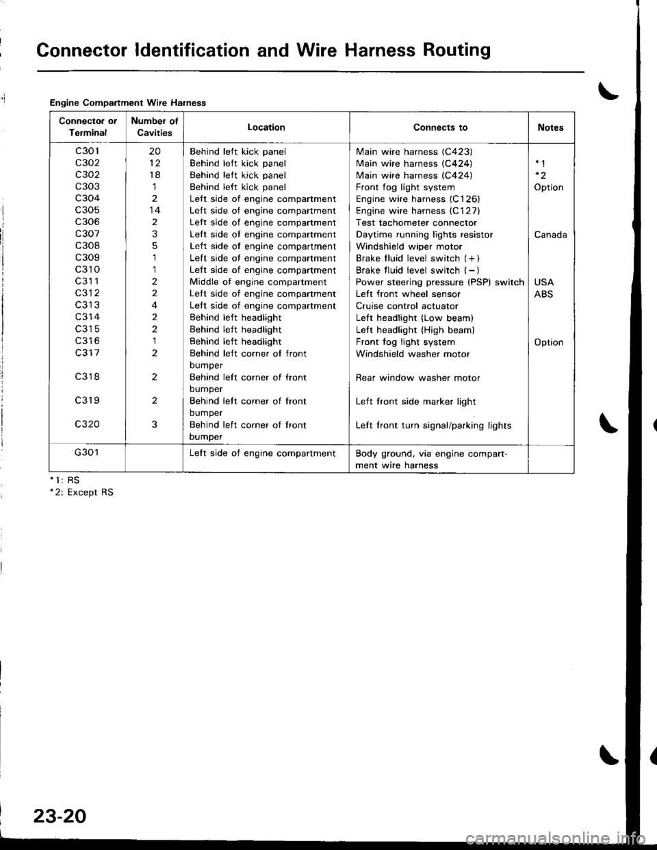
Connector ldentification and Wire Harness Routing
Engine Compartment Wire Halness
nll
Connectoa ot
Terminal
Number of
CavitiesLocationConnects toNotes
c301
c302
c 302
c303
c304
c306
c307
c308
c309
c310
c3l 1
c312
c314
c316
c317
c318
c319
c320
20
't8
1
14
2
3
5
1
1
2
2
4
2
2
1
2
2
2
3
Behind left kick panel
Behind left kick panel
Behind left kick panel
Behind left kick panel
Lett side of engine compartment
Lett side of engine companment
Lett side of engine compartment
Left side of engine compartment
Left side of engine compartment
Left side of engine compartment
Left side of engine compartment
Middle of engine compartment
Lett side of engine companment
Left side of engine compartment
Behind left headlight
Behind left headlight
Behind left headlight
Behind left corner of front
DUmper
Behind left corner ol front
bumper
Behind lett corner of front
bumper
Behind left co.ner of lront
bumper
Main wire harness (C423)
Main wire harness {C424)
N4ain wire harness (C424)
Front fog light system
Engine wire harness (C126)
Engine wire harness (C'127)
Test tachometer connector
Daytime running lights resistor
Windshield wiper motor
Brake f luid level switch (+ )
Brake f luid level switch ( - )
Power steering pressure (PSP) switch
Lett front wheel sensor
Cruise control actuator
LeIt headlight (Low beam)
Lett headlight {High beam)
Front fog light system
Windshield washer motor
Rear window washer motor
Left front side marker light
Left front turn signal/parking lights
Option
Canada
USA
ABS
Option
G301Lelt side of engine compartmentBody ground, via engine compart-
ment wire harness
23-20
Page 1079 of 1681
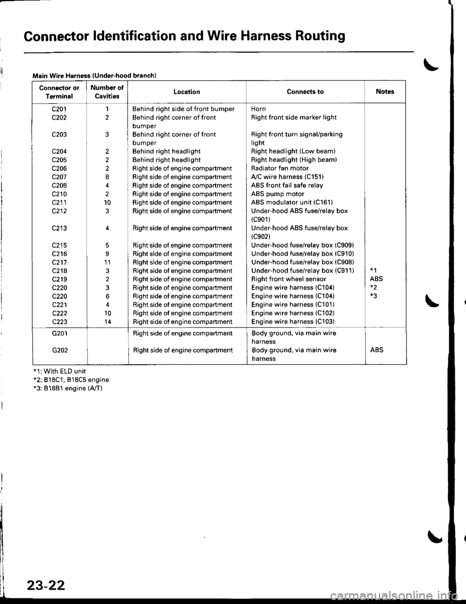
Connector ldentification and Wire Harness Routing
Main Wire Harness (Under-hood branchl
Conneqtor or
Terminal
Number ol
CavitiesLocationConnests toNotes
c201
c202
c203
c204
c205
c206
c207
c208
c210
c211
c213
c215
c216
c211
c218
c2r 9
c220
c220
c221
c222
c223
1
2
2
2
2
8
2
10
5
9'11
3
2
3
6
10
14
Behind right side of front bumper
Behind right corner of front
bumper
Behind right corner of front
DUmper
Behind right headlight
Behind right headlight
Right side of engine compartment
Right side of engine compartment
Right side of engine compartment
Right side of engine compartment
Right side of engine compartment
Right side of engine compartment
Right side ot engine compartment
Right side of engine compartment
Right side of engine compartment
Right side of engine compartment
Right side of engine compartment
Right side of engine compartment
Right side of engine compartment
Right side oI engine companment
Right side ot engine compartment
Right side ot engine compartment
Right side of engine compartment
norn
Right front side marker light
Right front turn signaUparking
lig ht
Right headlight (Low beam)
Right headlight (High beam)
Radiator lan motor
A"/C wire harness (C151)
ABS front fail safe relay
ABS pump motor
ABS modulator unit (C151)
Under-hood ABS fuse/relay box(c901)
Under-hood ABS fuse/relay box
{c902}
Under-hood fuse/relay box (C909)
Under-hood fuse/relay box (C910)
Underhood fuse/relay box (C908)
Under-hood fuse/relay box (C911)
Right front wheel sensor
Engine wire harness {C104)
Engine wire harness (C104)
Engine wire harness (C101)
Engine wire harness {C102)
Engine wire harness (C103)
*1
ABS
G201
G202
Right side of engine compartment
Right side of engine compartment
Body ground. via main wire
narness
Body ground, via main wire
harness
ABS
+1:With ELD unit*2: B18C't, 818C5 engine*3: 81881 engine (A,/T)
23-22