Stabilizer HONDA INTEGRA 1998 4.G Workshop Manual
[x] Cancel search | Manufacturer: HONDA, Model Year: 1998, Model line: INTEGRA, Model: HONDA INTEGRA 1998 4.GPages: 1681, PDF Size: 54.22 MB
Page 713 of 1681
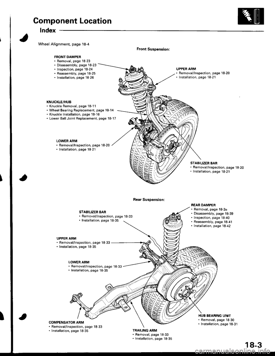
Component Location
lndex
Wheel Alignment, page 18-4
FRONT DAMPER. Removal, page 18 23' Disassembly, page 18-23. Inspection, page 18-24. Reassembly, page 18-25. lnstallation. page 18 26
KNUCKLE/HUB. Knuckle Removal, page 18-11'Wheel Bearing Replacement, page 18-14' Knuckle lnst6llation, page 18-16. Lower BallJoint Replacement, page 18-17
LOWER ARM. Removal/lnspection, page 18-20. lnstallation, page l8 21
Front SusDonsion:
Rear Susoension:
UPPER ARMRemoval/lnspection, page 18-20Installation, page 18-21
STABILIZER BARRemoval/lnspectaon, page 18-33Installation, page 18-35
STABILIZER BARRemoval/lnspection, page 18-20Installation, page 18,21
REAR DAMPER. Removal, page 18-3o. Disassembly, page 18-39' Inspection, page 18-40. Reassembly, page l8-41. Installation, page 18,42
UPPER ARM. Removal/lnspection, page l8 33. Installation, page 18-35
LOWER ARM. Removal/lnspection, page 18,33. lnstallation, page 18-35
ICOMPENSATOR ARM. Removal/lnspection, page 18 33. Installation, page 18-35
HUB BEARING UNIT. Bemoval, page 18'30. Installation, page 18,31
TRAILING ARM. Removal, page 18-33. lnstallation, page 18-35
18-3
Page 730 of 1681
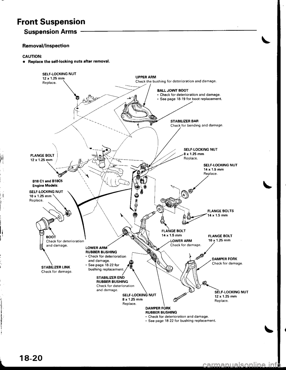
Front Suspension
Removal/lnspection
CAUTION:
. Replacs ihe self-locking nuts after r6moval'
SELF-LOCKING NUT12 x 'l.25 mmReplace.
UPPER ARMCheck the bushing for deterioration and damage.
Suspension Arms
818 Cl and B18C5
Engin6 Mod.ls:
SELF.LOCKING NUT10 x 1.25 mmReplace.
BALL JOINT BOOT. Check for deterioration and damage.' See page 18 19 for boot replacement.
STABILIZER BARCheck for bending and damage.
SELF-LOCKING NUTx 1-25 mmReolace,
14 x 1.5 mm
SELF.LOCKING NUT14 x 1.5 mmReplace.
FLANGE BOLTS14 x l.5 mm
FLANGE BOLT10 x 1.25 mmCheck for deteriorationano oamage,LOWER ARMCheck for damage.LOWER ARMRUBBER BUSHING. Check for deteriorationano oamage.. See page 18-22 tor
OAMPER FORKCheck for damage
bushing replacement.
and damage.
STABILIZER ENDRUBBER BUSHINGCheck f or deterioration
-LOCKING NUT12 x 1.25 mmReplace.
OAMPER FORKRUBBER BUSHING. Check for deterioration and damage.. See page 18 22 for bushing replacement.
STABILIZER LINK
1A-20
Page 731 of 1681
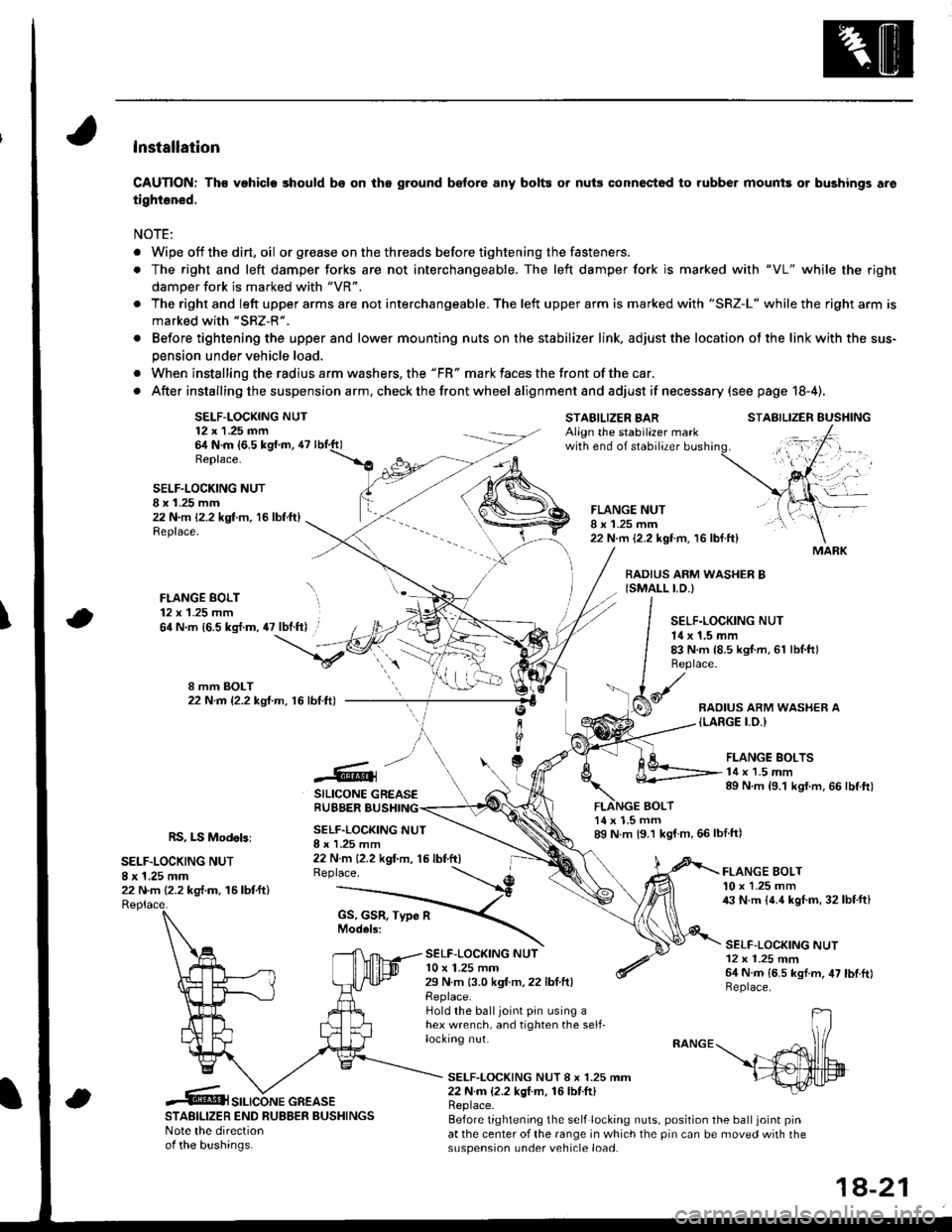
lnstallation
CAUTION: Th€ vehiclo should bs on the ground b€fore any bolts or nuis connectod to rubber mounis or bushings aro
tightened.
NOTE:
. Wipe off thedirt,oil or gr€ase on the threads before tightening the fasteners.
. The right and left damper forks are not interchangeable. The left damper fork is ma.ked with "VL" while the righr
damoer fork is marked with "VR".
. The right and left upper arms are not interchangeable. The left upper arm is marked with "SRZ-L" while the right arm is
marked with "SRZ-R".
. Before tightening the upper and lower mounting nuts on the stabilizer link, adjust the location ot the link with the sus-
pension under vehicle load.
. When installing the radius arm washers, the "FR" mark faces the front ofthe car.
. After installing the suspension a rm, check the front wheel alignmentand adjust if necesssry (see page 18-4).
SELF-LOCKING NUT12 x 1.25 nn64 N.m {6,5 kg{.m, 47Replace.
STABILIZER BARAlign the stabilazer markwith end of stabilizer
BOLT
STABILIZER EUSHING
SELF.LOCKING NUTI x 1.25 mm22 N.m 12.2 kgt m, 16 lbf.ft)Replace.
FLANGE BOLT12 x 1.25 mm
FLANGE NUTI x 1.25 mm22 N.m {2.2 kgt m. 16 lbf.ft}
BADIUS ARM WASHER B{SMALL I.D.)
\64 N.m {6.5 kg{.m, 47 lbt.ft) .SELF.LOCKING NUT14 x 1.5 mm83 N.m {8.5 kgI.m, 61 lbl.ftlReplace.
RAOIUS ARM WASHER A{LARGE I.O.I
.@]
SILICONE GREASERUBBER BUSHING
FLANGE BOLTS14 x 1.5 mm89 N.m {9.1 kgf.m, 66 lbtft)
RS, LS Modebi
SELF.LOCKING NUT8 x 1.25 mm22 N.m (2.2 kg,f.m. 16lbtftl
SELF.LOCKING NUTI x I .25 mm22 N m {2.2 kgt'm, 15 lbf.ft)Replace.
14 x 1.5 mm89 N m {9.1 kgf m,66lblft)
SELF-LOC(ING NUTl0 x 1.25 mm29 N.m 13.0 kgf.m,22 lbtftlReplace.Hold the balljoint pin using ahex wrench, and tighten the self-locking nut.
FLANGE BOLT10 x 1.25 mm43 N.m {4.4 kgl.m, 32lbf.ft}
SELF-LOCKING NUT12 x 1.25 mm64 N.m {6.5 kgf.m, 47 lbtftlReplace.
SELF-LOCKING NUT 8 x 1.25 mm22 N.m {2.2 kgI m, 16lbf.ft)
STABILIZER END RUBBER BUSHINGSNote the directionof the bushinas.
Replace.Before tightening the self locking nuts, position the ball joint pinat the center of the range in which the pin can be moved with thesuspension under vehicle load.
MARK
SILICONE GREASE
1A-21
Page 742 of 1681
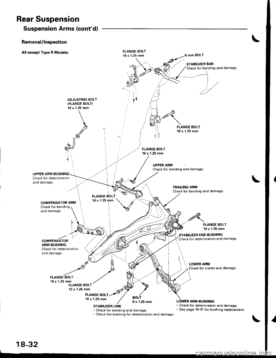
Rear Suspension
Suspension Arms (cont'dl
Removal/lnspection
All except Type R Models:mm BOLT
STABILIZER BARCheck for bending and damage.
AOJUSTING BOLT(FLANGE BOLT)'10 x 1.25 mm
FLANGE BOLT10 x 1.25 mm
UPPER ARMCheck for bending and damage.
UPPER ARM BUSHINGCheck for deteriorationand damage.
COMPENSATOR ARMCheck for bendingand damage,
FLANGE BOLT'10 x 1.25 mm
STABILIZER END BUSHING
Check for deterioration and damage.COMPENSATORARM BUSHINGCheck for deteriorationand damage-
FLANGE EOLTl0 x 1.25 mmBOL8 x 1.25 mmSTABILIZER LINK. Check for bending and damage.. Check the bushing for deterioration and damage.
ARM BUSHING
18-32
. Check for deterioration and damage.. See page 18-37Ior bushing replacement.
Page 743 of 1681
)
)
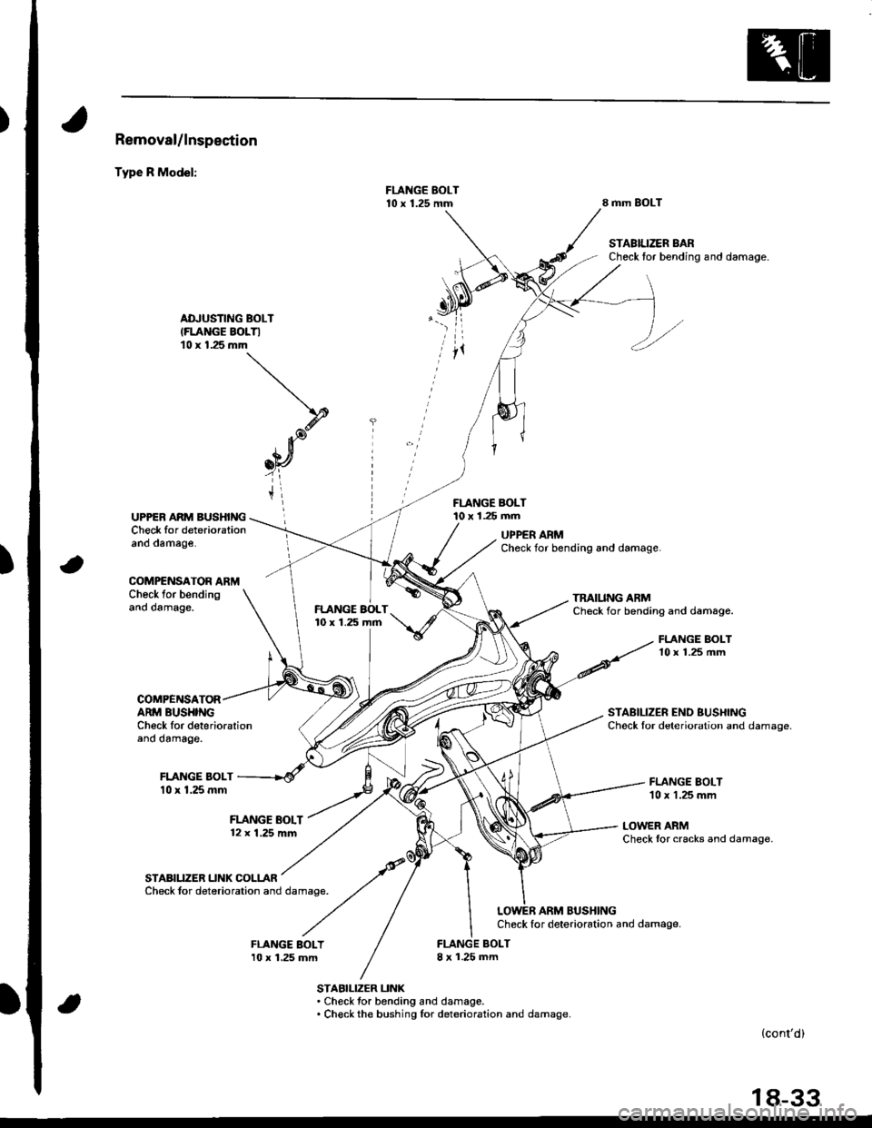
Removal/lnspection
Type R Model:
8 mm SOLT
STABIUZER BARCheck tor bending and damage.
ADJUSTING BOLT(FLANGE BOLTI10 x 1.25 mm
FLANGE BOLT10 x 1.25 mmUPPER ARM BUSHINGCheck for deteriorationano oamage.UPPER ARMCheck for bending and damage.
COMPENSATOR ARMCheck for bendingano oamage,TMIUNG ARMCheck for bending and damage.
COMPENSATORARM BUSHINGCh6ck Ior deteriorationano oamage.
FLANGE BOLT10 x 1.25 mm
STABILIZER END BUSHINGChock lor deterioration and damage.
FLANGE BOLT10 x 1.25 mm
LOWER ARMCheck tor cracks and damage.
STABIUZER UNK COLLARCheck for deterioration and damage.
LOWEB ARM BUSHINGCheck for deterioration and damage.
BOLTI x 1.25 mm
STABILIZER UNK. Check tor bending and damage.. Check the bushing lor deterioration and damage.
(cont'd)
18-33
10 x 1.25 mm
Page 744 of 1681
Rear Suspension
Suspension Arms (cont'dl
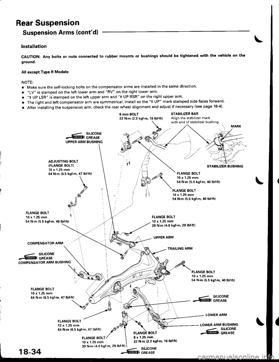
Installation
CAUTION: Any bolB or nuts connected to rubber mounts or bushings should be tightened with the vehicl. on th6
ground.
All except Type R Models:
NOTEi
. Make sure the self-locking bolts on the compensator arms are installed in the same direction.
. "LV" is stamped on the left lower arm and "RV" on the right lower arm.
. "i UP LSR" is stamped on the lett upper arm and "f UP RSR" on the right upper arm.
. The rightand left compensator arm are symmetrical. Install sothe "l UP" mark stamped side faces forward.
. After installing the suspension arm, check the rear wheel alignmentand adjust if necessary (see page 18-4).
I mm BOLT22 N.m {2.2 kgtm, 16lbtft}STABILIZER BARAlign the stabilizer markwith end of stabilizer bushing.
FLANGE BOLT10 x 1.25 mm54 N.m {5.5 kgf.m.40lbtft}
FLANGE BOLTl0 x 1.25 mm39 N m {{.0 kgt.m,29 lbtftl
UPPER ARM
TRAILING ARM
FLANGE EOLT'10 x 1.25 mm54 N.m {5.5 kgf.m, 40lbf.ft}
COMPENSATOR ARM
.-/ SILICONE.5tr@l GREASECOMPENSATOR ARM BUSHING
FLANGE BOI-T10 x 1.25 mm54 N.m (5.5 kgf.m, {O lbf.ft)
FLANGE BOLT10 x 1.25 mm64 N.m 16.5 kgl.m.47 lbf.ft)--- SILICONE.S!@l GREASE
LOWER ARM
LOWER ARM BUSI{ING
-- SILIGONE.S@l GREASE
FLANGE BOLT12 x 1.25 mm64 N.m {6.5 kgf m, 47 lbt.ftl -P'a
,amce gotr/
10 x 1.25 mm
BOLT8 x 1.25 mm22 N.m (2.2 kgt'm, 16 lbf'ftl
39 N.m (4.0 kgf m.29lbtft)stLtcoNEGREASE
UPPER ARM BUSHING
.-.- SILICONES@l GREASE
ADJUSTING BOLT
{FLANGE BOLT)10 x 1.25 mm64 N.m (6.5 kgf.m, 47 lbtft)
k
.g
iP
6[r,
i',
STABILIZER BUSHING
FLANGE BOLT10 x 1.25 mm54 N.m 15.5 kgt.m, 40 lbf.ftl
18-34--Rq
Page 745 of 1681
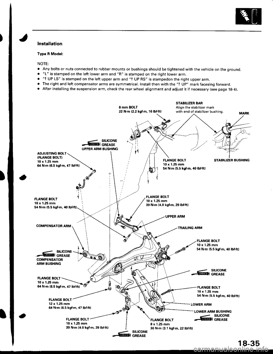
)Installation
Typ€ R Model:
NOTE;
. Any bolts or nuts connected to rubber mounts or bushings should be tightened with the vehicle on the ground.. "L" is stamped on the left lower arm and "R" is stamped on the right lower arm.. "l UP LS" is stamped on the left upper arm and "l UP RS" is stampedon the right upper arm.. The right and left compensator arms are symmetrical. Install then with the "1 Up" mark facesing forward. After installing the suspension arm, checkthe rearwheel alignmentand adjustitif necessary(see page 18-4).
8 mm BOLT22 N.m (2.2 kgl m, 16 lbt.ftl
STABILIZER BARAlign the stabilizer markwith end of stabilizer bushing.
-ArUPPEB ARM
rz tot+,t \
\.d'. Ja),n[
_oY
t\
a
stLtcoNEGREASEBUSHINGADJUSTING BOLTIFLANGE BOLT}l0 x 1.25 mm6,4 N.m {6.5 kgt m,
FLANGE BOLT'10 x 1.25 mm5,[ N.m 15.5 kg[.m. 40 lbt.ftl
STABILIZER BUSHING
FLANGE BOLT10 x 1.25 mm
FLANGE BOLT10 x 1.25 mrn39 N.m (,r.0 kgf.m.29 lbtftl5/a N.m 15.5 kgl.m, a0
COMPENSATOR AFM
UPPER ARM
TRAILING ARM
FLANGE BOLT10 x 1.25 mm54 N.m 15.5 kgf.m, .{) lbf.ftl..- SILICONE.4@i cREAsECOMPENSATORARM BUSHING
FLANGE BOLI10 r 1.25 mm6,4 N.m (6.5 kgl.m, 47 lbf.Itl
FLANGE BOLT12 x 1.25 mm6a N.m 16.5 kgl.m, a7 lbf.ftl
, ror"orr /
l0 x 1.25 mm39 N.m 14.0 kgf.m, 29 lbt.ftl
FLANGE BOLT8 x 1.25 mm30 N.m 13.1 kgt m, 22 lbf.ftl
..- SILICONE.@ll GREASE
FLANGE BOLT10 x 1.25 mm54 N.m {5.5 kgt m, 40 lbtftl
LOWER ARM
LOWER ARM EUSHING
a
--- SILICONE@l GREASE
-- slLlcoNE&l GREASE
18-35
Page 846 of 1681
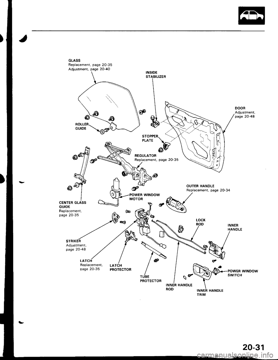
INSIDESTABILIZER
REGULATORReplacement, page 20-35
@
CENTER GLASSGUIDEBeplacement,page 20'35
INNERHANO
h^1-\7
vLATCHPROTECTOR
Replacement,page 2o-35
\
Sr
20-31
Page 850 of 1681
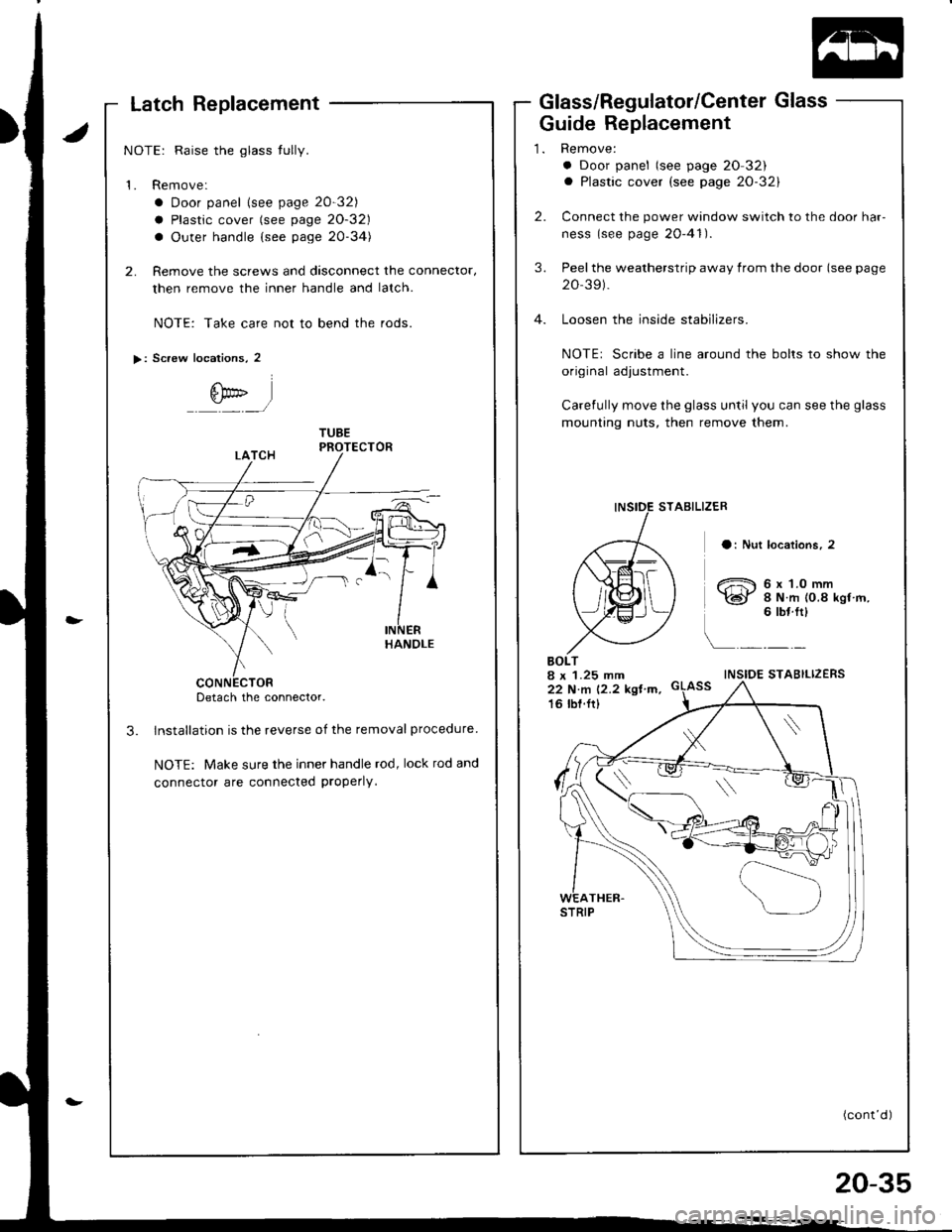
Latch Replacement
NOTE: Raise the glass tully.
1. Remove:
a Door panel lsee page 20-32)
a Plastic cover (see page 20-32)
a Outer handle {see page 20-34)
2. Remove the screws and dasconnect the connector,
then remove the inner handle and lalch.
NOTE: Take care not to bend the rods.
Detach the connector.
Installation is the reverse of the removal procedure
NOTE: Make sure the inner handle rod, lock rod and
connector are connected properly.
Scaew locations, 2
€tr' l-,/
Glass/Regulatol/Center Glass
Guide Replacement
BOLT8 x 1.25 mm22 N.n 12.2 kgl'm.16 lbt.ft)
a Door panel (see page 20 32)a Plastic cover (see page 20-32)
Connect the power window switch to the door har-
ness (see page 20-41).
Peel the weatherstrip away from the door (see page
Loosen the inside stabilizers.
NOTEr Scribe a line around the bolts to show the
original adjustment.
Carefully move the glass until you can see the glass
mounting nuts, then remove them.
STAEILIZER
a: Nut locations, 2
t,h6xl.omm)@[ a ru.m ro.8 ksr'm.
i
6 tbritl
\
INSIDE STABILIZERS
(cont'd )
20-35
Page 855 of 1681
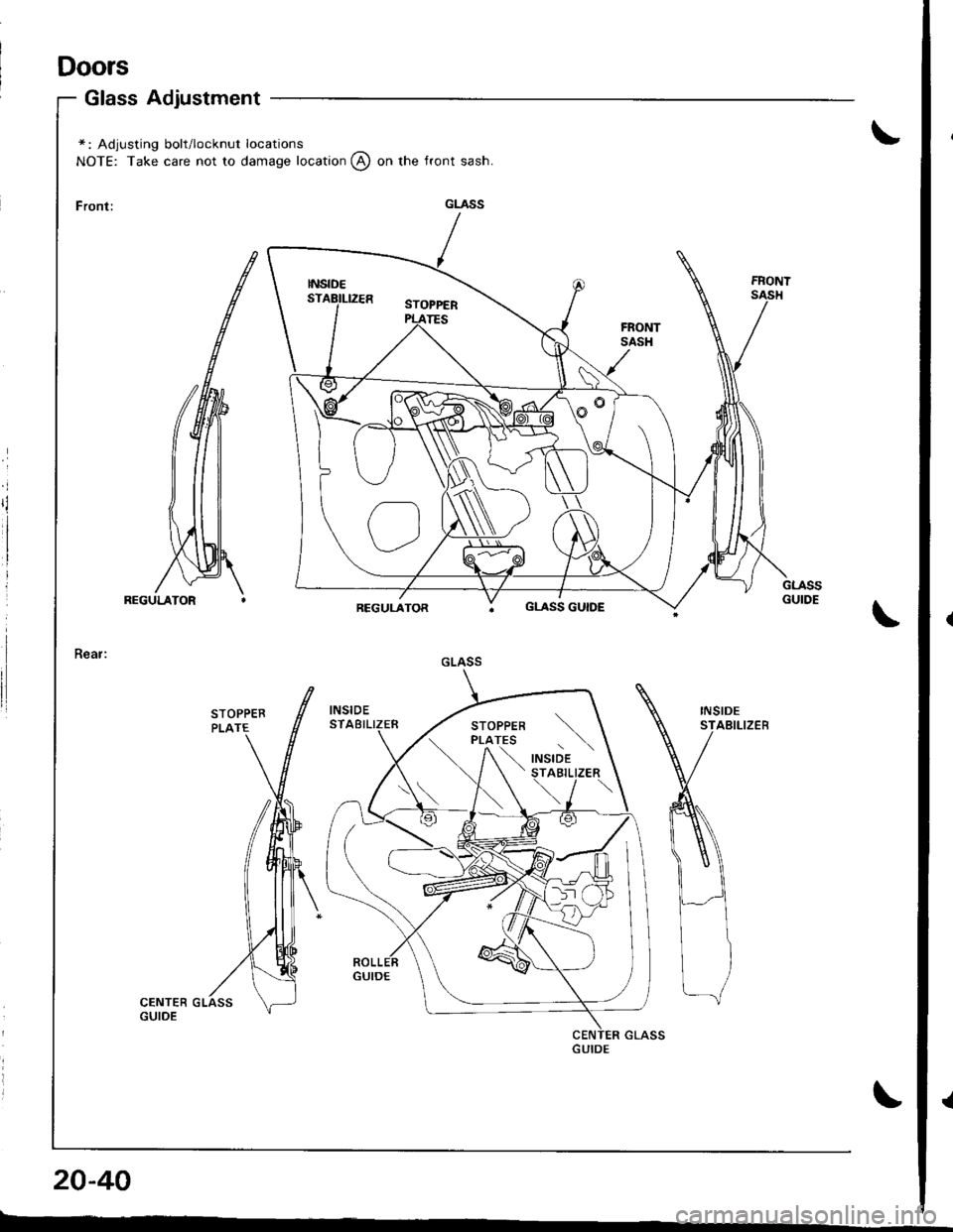
Doors
Glass Adjustment
\*: Adjusting bolt/locknut locations
NOTE: Take care not to damage location @ on the front sash.
\
INSIDESTABILIZEB
\
20-40
r---
GLASS
GLASS GUIDE
GLASS
\
,"a,o'a t \STABILIZER
\../ \