Stabilizer HONDA INTEGRA 1998 4.G User Guide
[x] Cancel search | Manufacturer: HONDA, Model Year: 1998, Model line: INTEGRA, Model: HONDA INTEGRA 1998 4.GPages: 1681, PDF Size: 54.22 MB
Page 859 of 1681

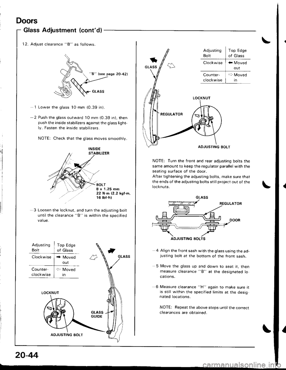
12. Adjust clearance "8" as follows.
)^
d "8" {see pase 20-42}
(6
:\D \crnss
1 Lower the glass 1O mm (0.39 in).
2 Push the glass outward lO mm (0.39 in), thenpush the inside stabilizers against the glass light-
ly. Fasten the inside stabilizers.
NOTE: Check that the glass moves smoothly.
i
ilINSID€STAEILIZER
BOLT8 x 1.25 mm22 N.m 12.2 kgl.m,16 tbt ftl
3 Loosen the lo"knrt, "nd turn the adjusting bolt
until the clearance "B" is within the specilied
value.
Adiusting
Bolt
Clockwise
Top Edge
of Glass
Counter-
cloc kwise
LOCKNUT
ADJUSTING BOLT
20-44
Doors
Glass Adjustment (cont'd)
out
\
LOCKNUT
REGULATOR
ADJUSTING BOLT
NOTE: Turn the front and rear adjusting bolts the
same amount to keep the regulator parallel with the
seating sur{ace ot the door.
After tightening the adjusting bolts, make sure that
the ends of the adjusting bolts still project out of the
locknuts.
4 Align the front sash with the glass using the ad-justing bolt at the bottom of the lront sash.
5 Move the glass up and down to seat it, thenmeasure clearance "B" at the designated locations.
6 Measure clearance "H" again to make sure itis still within the specified limirs at the desig,nated locations.
NOTE: Repeat the above steps until the correct
clearances are obtained.
Top Edge
of Glass
GLASS
ADJUSTING BOLTS
I
Page 861 of 1681

Doors
Glass Adjustment (cont'dl
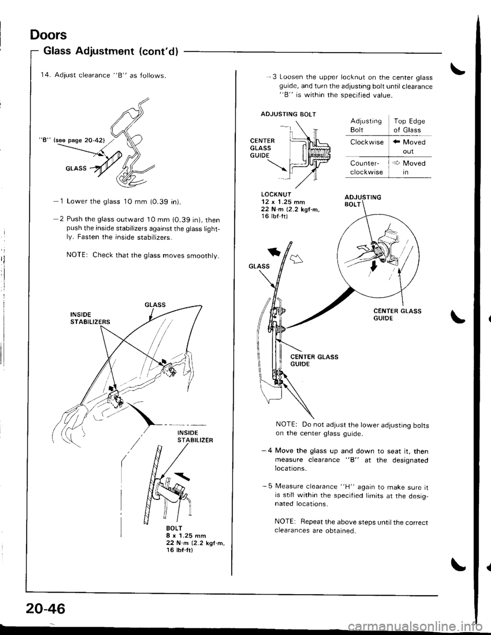
'14. Adiust clearance "B" as Jollows.
"8" lsee page 20-421
- 1 Lower the glass 1O mm (0.39 in).
2 Push the glass outward 10 mm 10.39 in), thenpush the inside stabilizers against the glass light-ly. Fasten the inside stabrIzers.
NOTEr Check that rhe glass moves smoothly.
BOLT8 x 1.25 mm22 N.m (2.2 kgf.m,'t6 tbt.fr)
20-46
-
-.\
CENTER [L\LGLAss lilffiGUTDE I li$lliun
\fiJrtrlAl-,/"
.-3 Loosen the upper locknut on the center glassguide, and turn the adjusting bolt until clearance"B" is within the specified value.
ADJUSTING BOLT
LOCKNUT
22 N.m 12.2 kgt tn,16 lb{.ttl
*
GLASS
NOTE: Do not adjust the lower adjusting boltson the center glass guide.
-4 Move the glass up and down to seat jt, then
measure clearance "B" at the designatedlocations.
- 5 Measure clearance "H" again to make sure itis still within the specified limits ar the desig,nated locations.
NOTE: Repeat the above steps until the correctclearances are obtained.
Top Edge
of Glass
Page 1658 of 1681

ITEMMETRICIENGLISHINOTES
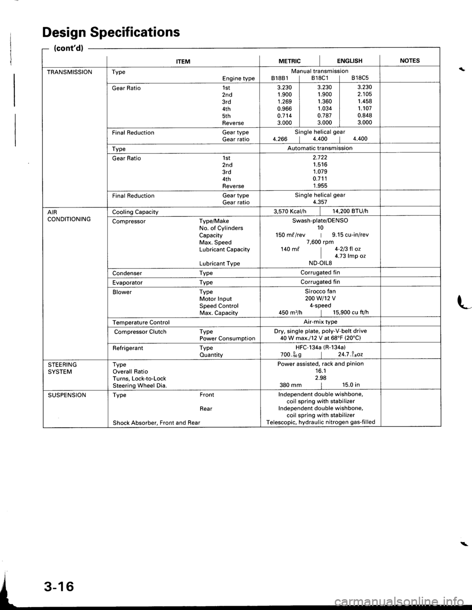
TRANSMISSIONTypeEngine typeManual transmissionB18B1lB18C1lB18C5
Gear Ratio1st2nd3rd4th5thReverse
3.230't.900
1.2690.9660.7143.000
3.2301.9001.3601.0340.7873.000
3.2302.1051.4581.1070.8483.000
Final Reduction Gear typeGear ratioSingle helical gear4.266 14.400 14.400
TypeAutomatic transmission
Gear Ratio 1st2nd3rd4thReverse
2.722't.516
1.0790.7111.955
Final Reduction GeartypeGear ratioSingle helical gear4.357
AIRCONDITIONINGCooling Capacity3.570 Kcar/h | 14,200 BTU/h
Compressor Type/MakeNo. of CylindersCapacityMax. SpeedLubricant Capacity
Lubricant Type
Swash-plate/DENSO10150 m//rev | 9.15 cu-in/rev7,600 rpm140 m/ | 4-213 fl oz
I c.z3 |rp o.ND.OILS
Condenser TypeCorrugated fin
Evaporator TypeCorrugated fin
Blower TypeMotor InputSpeed ControlMax. Capacity
Sirocco fan200w1't2v4-speed450 m3/h | 15,900 cu fVh
Temperature ControlAir-mix type
Compressor Clutch TypePower ConsumptionDry. single plate, poly-V-belt drive40W max.l12 V at 68'F (20'C)
Refrigerant TypeQuantityHFC-134a (R-134a)
700_309 | 24.7_?.aoz
STEERINGSYSTEMTypeOverall RatioTurns, Lock-to-LockSteering Wheel Dia.
Power assisted, rack and pinion16.12.98380 mm | 15.0 in
SUSPENSIONType Front
Rear
Shock Absorber, Front and Rear
Independent double wishbone,coil spring with stabilizerIndependent double wishbone,coil spring with stabilizerTelescopic, hydraulic nitrogen gas-filled
Design Specifications
(cont'd)
L
\