change wheel HONDA INTEGRA 1998 4.G Workshop Manual
[x] Cancel search | Manufacturer: HONDA, Model Year: 1998, Model line: INTEGRA, Model: HONDA INTEGRA 1998 4.GPages: 1681, PDF Size: 54.22 MB
Page 147 of 1681
I
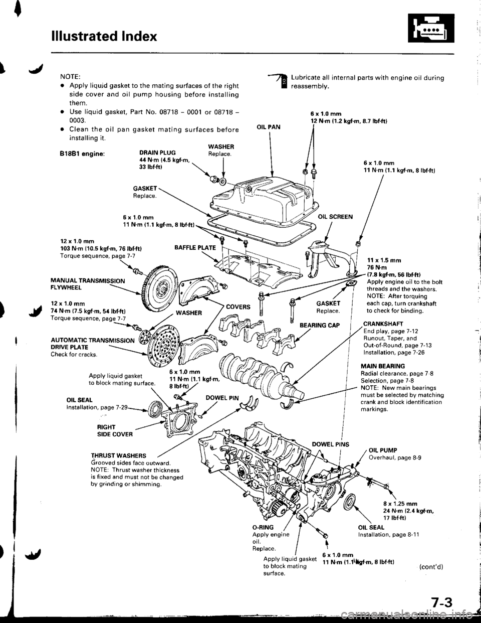
lllustrated Index
INOTE:
. Apply liqujd gasket to the mating surfaces ot the right
side cover and oil pump housing before installing
them.
. Use liquid gasket,
0003.
. Clea n the oil pan
installing it.
B18Bl engine:
Part No. 087'18 - 0001 or 08718 -
gasket mating surfaces before
Lubricate all internal parts with engine oil during
reassemDly.
6x1.0mm12 N.m {1.2 kg{.m,8.7 lbt.ft}
6x1.0mm11 N.m 11.1 kg'f.m,8 lbt.ftl
OIL SCREEN
DEAIN PLUG4il N.m 14.5 kgt m,33 tbtft)
BAFFLE PLATE
6x1.0mm1'l N.m (1.1 kgt.m,8 rbr.ftl
OIL PAN
O.FING
CAP
DOWEL PINS
WASHERReplace.
GASKETReplace.
6x1.0mm11 N.m (1.1 kgl.m, 8 lbl.ft)
12 x 1.0 mm103 Nm 110.5ks{.m,76lbf.ft}
MANUAL TRANSMISSIONFLYWHEEL
12 x 1.0 mm74 N.m 17.5 kgf.m,54lbf.tr)Torque sequence, page 7-7
AUTOMATIC TRANSMISSION
WASHERcovERsGASKETReplace.
11 x 1.5 mm76 N.m17.8 kgt m, 56 lbtft)Apply engine oilto the boltthreads and the washers.NOTE: After torquingeach cap, turn crankshaftto check for binding.
ORIVE PLATECheck for cracks.
Apply liquid gasketto block mating surface.
CRANKSHAFTEnd play, page 7-12Runout, Taper, andOut-of'Round, page 7-13Installation, page 7-26
MAIN AEARINGRadialclearance, page 7 8Selection, page 7'8NOTE: New main bearingsmust be selected by matchingcrank and block identificationmarkrngs.
I
i
OIL SEALlnstallation, page 7
RIGHTSIDE COVER
THRUST WASHERSGrooved sides face outward.NOTE: Thrust washer thicknessis fixed and must not be changedby grinding or shamming.
8 x 1.25 mm21 N..n l2.1kga'r,�,17 tbf.ft)
OIL SEALInstallation, page 8-1 1Apply engineorl.Replace.
Apply liquid gasket
to block matingsurface,
6x1.0mm11 N.m t1.lilh{.m,I lbf.ft}(cont'd)
Page 245 of 1681
I
t
h,,l,!
il
Troubleshooting
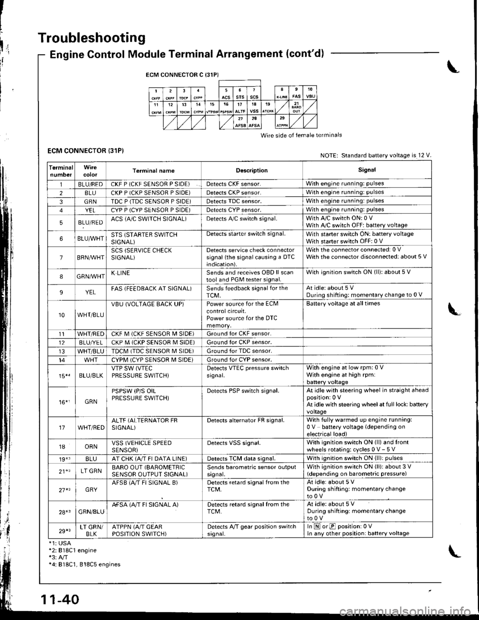
ECM CONNECTOR {31P)
Engine Control Module Terminal Arrangement (cont'd)
ECM CONNECTOR C {31P)
235srsscs1112t31515t71A19
2A
Wire side of lemale terminals
NOTE: Standard battery voltage is 12 V.
TerminalnumbercolorTerminal namoD6scriptionSignal
1BLU/REDCKF P (CKF SENSOR P SIDE)Detects CKF sensor.With engine running: pulses
28LUCKP P (CKP SENSOR P SIDE)Detects CKP sensor.With engine running: pulses
3GRNTDC P {TDC SENSOR P SIDE)Detects TDC sensor,With engine running: pulses
YELCYP P (CYP SENSOR P SIDE)Detects CYP sensor,With engine running: pulses
5BLU/REDACS (AJC SWITCH SIGNAL)Detects A,/C switch signal.With A,/C switch ON: 0 VWith A,/C switch OFF: battery voltage
6BLUA/VHTSTS (STARTEB SWITCHSIGNAL)
Detects starter switch signal.With staner switch ON: battery voltageWith starter switch OFF: 0 V
7BRN,AiVHTSCS (SERVICE CHECKSIGNAL)Detects service check connectorsignal (the signalcausing a DTC;ndication).
With the co n nector con nected: 0 VWath the connector disconnected: about 5 V
8GRNAVHTK LINESends and receives OBD ll scantool and PGM tester signal.With ignition switch ON (ll): about 5 V
9YELFAS lFEEDBACK AT SIGNAL)Sends feedback signal for theTCM,At idle: about 5 VDuring shifting: momenlary change to 0 V
10WHT/BLU
VBU (VOLTAGE BACK UP)Power source for the ECMcontrolcircuit,Power source for the DTC
Battery voltage at all times
t1WHT/REDCKF M (CKF SENSOR I\4 SIDE)Ground for CKF sensor.
12BLUI/E LCKP M (CKP SENSOR M SIDE)Ground for CKP sensor.
WHT/BLUTDCM (TDC SENSOR M SIDE)Ground tor TDC sensor.
14CYPM (CYP SENSOR M SIDE)Ground for CYP sensor.
15*.BLU/BLKVTP SW (VTEC
PRESSUFE SWITCH)Detects VTEC pressure switchsr9nal.
With engine at low rpm:0 VWith engine at high rpmlbattery voltaqe
161,GRN
PSPSW (P/S OILPRESSURE SWITCH)Derecls PSP switch signal.At idle with steering wheel in straight aheadpositioni 0 VAt idle with steering wheelat full lock: batteryvoltage
17WHT/REDALTF (ALTERNATOR FRSIGNAL)Detects alternator FR signal.With fully warmed up engine running:0 V battery voltage (depending onelectrical load)
18ORNVSS (VEHICLE SPEEDSENSORiDetects VSS signal.With ignition switch ON (ll) and lrontwheels rotating: cycles 0 V- 5 V
19*3BLUAT CHK (A/T FI DATA LINE)Detects TCM data signal.With ignition switch ON (ll)i pulses
21*LT GRNBARO OUT (SAROMETRIC
SENSOR OUTPUT S!GNAL)Sends barometric sensor outputsrgnal,With ignition switch ON (ll): about 3 V(depending on barometric pressure)
27 x3GRYAFSB (A"/T FI SIGNAL B)Detects retard signal from theTCM,At idle: about 5 VDuring shifting: momentary changeto0V
28+1GRN/8LUA+SA (A/T FI SIGNAL A)Detects retard signal from theTCM.At idle: about 5 VDuring shifting: momentarV changeto0V
29+3LT GRN/BLKATPPN (A/T GEARPOSITION SWITCH)Detects A,/T gear position switchsrgnal-In E orE positionr 0VIn anv other position: battery voltage
*1: USA*2:818C1 engine*3: A/T*4: 818C1, 818C5 engines
Page 420 of 1681
Description
\J
t{
{
14-3
The automatic transmission is a combination of a 3-element torque converter and triple-shalt electronically controlled
automatic transmission which provides 4 speeds forward and 1 speed reverse. The entire unit is positioned in line with
the engrne.
Torque Converter, Gears, and Clutches
The torque converter consists of a pump, turbine, and stator, assembled in sigle unit. The torque converter is connected to
the engine crankshaft so they turn torether as a unit as the engine turns. Around the outside of the torque convener is a
ring gear which meshes with the starter pinion when the engine is being started. The entire torque converter assembly
serves as a flywheel while transmitting power to the transmission mainshaft.
The transmission has three parallel shafts; the mainshaft. the countershaft, and the sub shaft. The mainshaft is in-line with
the engine crankshaft.
The mainshaft includes the 1st, and 2ndl4th clutches,and gear for 3rd, 2nd, 4th, reverse, and 1st. (3rd gear is integral with
the mainshaft, while reverse gear is integral with the 4th gear.)
The countershaft includes the 3rd clutch and gears for 3rd,2nd, 4th, reverse, 1st, and parking. Reverse and 4th gears can
be loched to the countershaft at its center,providing 4th gear or reverse, depending on which way the selector is moved.
The sub-shaft includes the 1st-hold clutch and gears fo 1st and 4th.
The gears on the mainshaft are in constant mesh with those on the countersahft and sub-shaft.When certain combinations
of gears in the transmission are engaged by clutches. power in transmitted from the mainshaft to the countershaft via the
sub-shaft to orovude oil, lo'1. E, E. and E.
Electronic Control
The electronic control svstem consists of the Transmission Control Module (TCM), sensors, and four solenoid valves.
Shilting and lock-up are electronically controlled for comfortable driving under all conditions.
The TCM is located below the dashboard, behind the lelt side kick panel on the driver's side.
Hydraulic Control
The valve bodies include the main valve body, the secondary valve body, the regulator valve body, the serbvo body, and
the lock-up valve body, through the respective separator plates, They are bolted to the torque converter housing,
The main valve body contains the manual valve, the 1-2 shift valve, the 2-3 shitt valve, the Clutch Pressure Control
lCPC) valve, the 4th exhaust valve, the reliel valve, and the ATF pump gears.
The secondary valve body contains the 4-3 kick-down valve, the 3-2 kick-down valve, the 2-3 orifice control valve, the
3-4 shift valve, the orilice control valve, the modulator valve, and the servo control valve.
The regulator valve body contains the pressure regulator valve, the lock-up control valve, the torque converter check
valve, and the cooler check valve.
The servo body contains the servo valve, which is integrated with shift fork shaft, the throttle valve B, and the accumula-
tors.
The lock-up valve body contains the lock-up shift valve and the lock-up timing B valve, and is bolted to the regulator valve
ooqy.
Fluid from the regulator passes through the manual valve to the various control valves.
Shift Control Mechanism
Input to the TCM from various sensors located throughout the car determines which shift control solenoid valve should
be activated. Activating a shitt control solenoid valve changes modulator pressure, causing a shift valve to move. This
pressurizes a line to one ol the clutches, engaging that clutch and its corresponding gear.
Lock-uD Mechanism
In @ position, in 2nd, 3rd and 4th, and @ position in 3rd, pressurized fluid can be drained lrom the back oI the tor-
que converter through a fluid passage, causing the lock-up piston to be held against the torque converter cover. As this
takes place, the mainshaft rotates at the same speed as the engine crankshaft. Together with hydraulic control, the TCM
optimizes the timing of the lock-up mechanism.
The lock-up valves controlthe range of lock-up according to lock-up control solenoid valves A and B, and throttle valve B.
When lock-up control solenoid valves A and B activate, modulator pressure changes. Lock-up control solenoid valves
A and B are mounted on the torque converter housing, and are controlled by the TCM.
(cont'd)
Page 658 of 1681
INPUT SHAFT
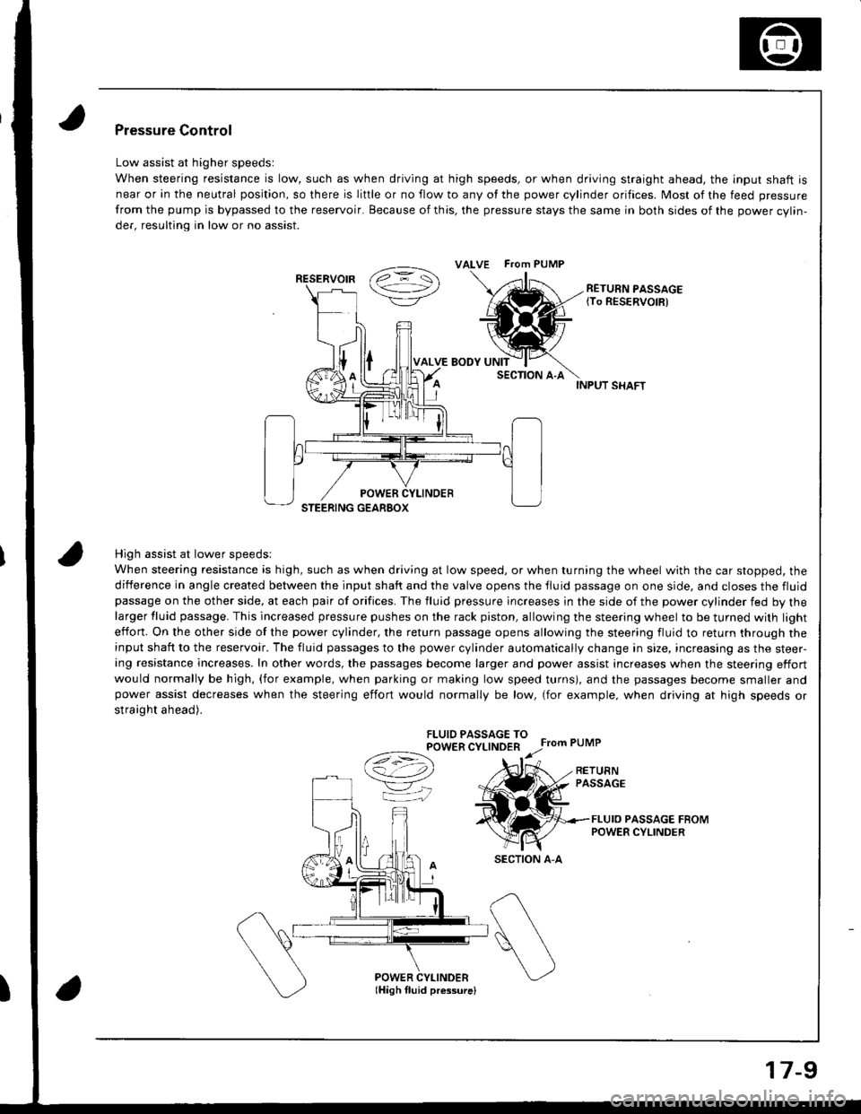
High assist at lower speedsl
When steering resistance is high, such as when driving at low speed, or when turning the wheel with the car stopped, the
diiference in angle created between the input shaft and the valve opens the tluid passage on one side, and closes the fluidpassage on the other side, at each pair of orifices. The fluid pressure lncreases in the side of the power cylinder fed by thelarger fluid passage. This increased pressure pushes on the rack piston, allowing the steering wheel to be turned with light
effon. On the other side of the power cylinder, the return passage opens allowing the steering fluid to return through theinput shaft to the reservoir. The fluid passages to the power cylinder automatically change in size, increasing as the steer-ing resistance increases. In other words, the passages become larger and power assist increases when the steering effort
would normally be high, (for example, when parking or making low speed turns), and the passages become smaller andpower assist decreases when the steering effort would normally be low, (for example, when driving at high speeds or
straight ahead).
FLUIO PASSAGE TOPOWER CYLINDER
Ce) r.r;
VK
Pressure Control
Low assist at higher speedsl
When steering resistance is low, such as when driving at high speeds, or when driving straight ahead. the lnput shaft is
near or in the neutral position, so there is liftle or no flow to any of the power cylinder orifices. Most of the feed pressure
from the pump is bypassed to the reservoir. Because of this, the pressure stays the same in both sides of the power cvlin-
der, resulting in low or no assist.
RETURN PASSAGE{To RESERVOIR)
POWER CYLINDERlHigh fluid pressurelI
ALVE FTom PUMP
RESERVOIR
SECTION A-A
17-9
Page 731 of 1681
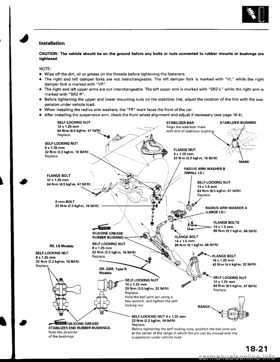
lnstallation
CAUTION: Th€ vehiclo should bs on the ground b€fore any bolts or nuis connectod to rubber mounis or bushings aro
tightened.
NOTE:
. Wipe off thedirt,oil or gr€ase on the threads before tightening the fasteners.
. The right and left damper forks are not interchangeable. The left damper fork is ma.ked with "VL" while the righr
damoer fork is marked with "VR".
. The right and left upper arms are not interchangeable. The left upper arm is marked with "SRZ-L" while the right arm is
marked with "SRZ-R".
. Before tightening the upper and lower mounting nuts on the stabilizer link, adjust the location ot the link with the sus-
pension under vehicle load.
. When installing the radius arm washers, the "FR" mark faces the front ofthe car.
. After installing the suspension a rm, check the front wheel alignmentand adjust if necesssry (see page 18-4).
SELF-LOCKING NUT12 x 1.25 nn64 N.m {6,5 kg{.m, 47Replace.
STABILIZER BARAlign the stabilazer markwith end of stabilizer
BOLT
STABILIZER EUSHING
SELF.LOCKING NUTI x 1.25 mm22 N.m 12.2 kgt m, 16 lbf.ft)Replace.
FLANGE BOLT12 x 1.25 mm
FLANGE NUTI x 1.25 mm22 N.m {2.2 kgt m. 16 lbf.ft}
BADIUS ARM WASHER B{SMALL I.D.)
\64 N.m {6.5 kg{.m, 47 lbt.ft) .SELF.LOCKING NUT14 x 1.5 mm83 N.m {8.5 kgI.m, 61 lbl.ftlReplace.
RAOIUS ARM WASHER A{LARGE I.O.I
.@]
SILICONE GREASERUBBER BUSHING
FLANGE BOLTS14 x 1.5 mm89 N.m {9.1 kgf.m, 66 lbtft)
RS, LS Modebi
SELF.LOCKING NUT8 x 1.25 mm22 N.m (2.2 kg,f.m. 16lbtftl
SELF.LOCKING NUTI x I .25 mm22 N m {2.2 kgt'm, 15 lbf.ft)Replace.
14 x 1.5 mm89 N m {9.1 kgf m,66lblft)
SELF-LOC(ING NUTl0 x 1.25 mm29 N.m 13.0 kgf.m,22 lbtftlReplace.Hold the balljoint pin using ahex wrench, and tighten the self-locking nut.
FLANGE BOLT10 x 1.25 mm43 N.m {4.4 kgl.m, 32lbf.ft}
SELF-LOCKING NUT12 x 1.25 mm64 N.m {6.5 kgf.m, 47 lbtftlReplace.
SELF-LOCKING NUT 8 x 1.25 mm22 N.m {2.2 kgI m, 16lbf.ft)
STABILIZER END RUBBER BUSHINGSNote the directionof the bushinas.
Replace.Before tightening the self locking nuts, position the ball joint pinat the center of the range in which the pin can be moved with thesuspension under vehicle load.
MARK
SILICONE GREASE
1A-21
Page 781 of 1681
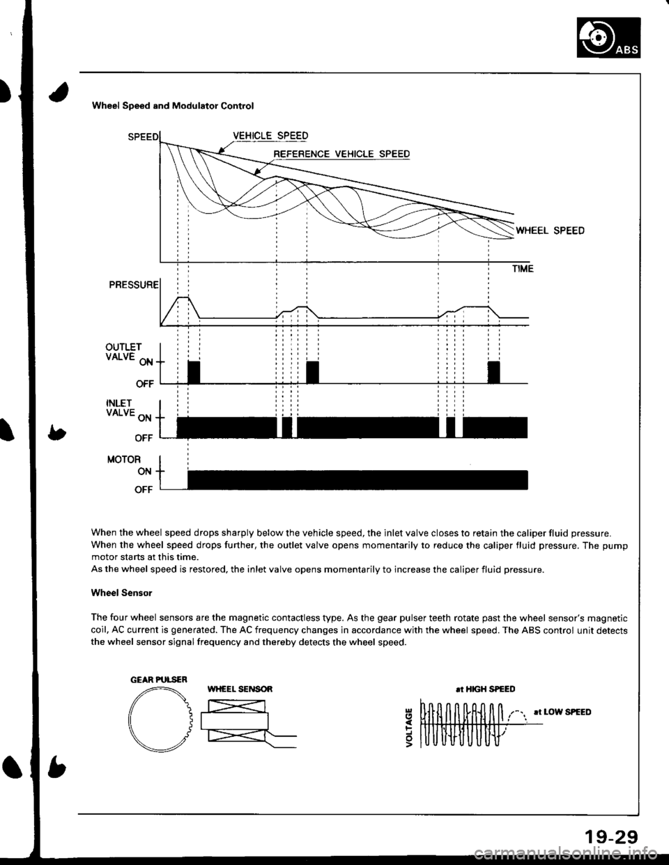
Wheel Speed and Modulator Control
OUTLETVALVE oN
OFF
INLETVALVE ON
OFF
MOTOR
ON
OFF
When the wheel speed drops sharply below the vehicle speed, the inlet valve closes to retain the caliper fluid pressure.
When the wheel speed drops further, the outlet valve opens momentarily to reduce the caliper fluid pressure. The pump
motor starts at this time.
As the wheel speed is restored, the inlet valve opens momentarily to increase the caliper fluid pressure.
Wheel Sensor
The four wheel sensors are the magnetic contactless type. As the gear pulser teeth rotate past the wheel sensor's magnetic
coil, AC current is generated. The AC frequency changes in accordance with the wheel speed. The ABS control unit detects
the wheel sensor signalfrequency and thereby detects the wheel speed.
rr LOW SPEED
5
GEAR PUTSER
19-29
Page 1648 of 1681
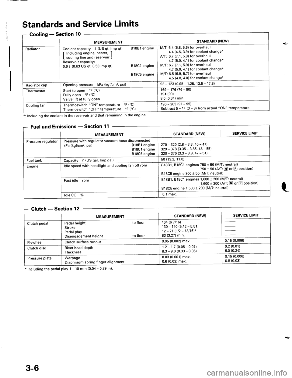
Standards and Service Limits
missions - Section 11
* Including the pedal play 1 - 10 mm (0.04 - 0.39 in).
0Gooling - Sectlon
MEASUREMENTSTANDARD (NEW}
RadiatorCoolant capacity / (US qt, lmp qt) 81881 engine
I Including engine, heater, II cooling line and reservoir IReservoir capacity:0.6 f (0.63 US qt, 0.53 lmp qt) 818C1 engine
818C5 engine
M/T: 6.4 (6.8, 5.6) for overhaul4.4 14.6,3.9) for coolant change*
A,/T: 6.7 (7.1, 5.9) for overhaul4.7 $.0,4.1)for coolant change*
M/T: 6.7 (7.1,5.9) for overhaul4.7 (5.0, 4.1) for coolant change*
M/T: 6.5 (6.9, 5.7) for overhaul4.5 (4.8, 4.0) for coolant change*
Radiator capOpening pressure kPa (kgf/cm'�, Psi)93 - 123 (0.95 - 1.25, 13.5 - 17.8)
ThermostatStart to open 'F ("C)
Fully open "F ("C)
Valve lift at fully open
169 - 176 (76 - 80)194 (90)
8.0 (0.31)min.
Cooling fanThermoswitch "ON" temperature "F ('C)
Thermoswitch "OFF" temperature "F ("C)196 - 203 (91 - 95)Subtract 5 - 14 (3 - 8) from actual "ON" temperature
*: Including the coolant in the reservoir and that remaining in the engine
Fuel and E
MEASUREMENTSTANDARD (NEW}SERVICE LIMIT
Pressure regulatorPressure with regulator vacuum hose disconnected
kPa (kgf/cm'�, psi) 81881 engine818C1 engine818C5 engine
270 - 320 (2.8 - 3.3, 40 - 47].
329 - 378 (3.35 - 3.85, 48 - 55)
320 - 370 (3.3 - 3.8, 47 -541
Fuel tankCapacity / (US gal, lmp gal)50 (13.2, 11.0)
Engineldle speed with headlight and cooling fan off rpm81881, 818C1 engines 750 t 50 (M/T: neutral)750 I 50 (A/T: N or E Position)818C5 engine 800 t 50 (M/T: neutral)
Fast idle rpmB1881, 818C1 engines 1,600 t 200 (M/T: neutral)1,600 t 200 (A/T: E or E Position)818C5 engine 1,500 t 200 (M/T: neutral)
ldle CO %0.1 max.
Clutch - Section 'lZ
MEASUREMENTSTANDARD (NEW}SERVICE LIMIT
Clutch pedalPedal height to floor
StrokePedal playDisengagement height to floor
164 (6 7/16)130 - 140 (5.12 - 5.51)12 -21 (12 - 13/16)*83 (3.27) min.
FlywheelClutch surface runoul0.05 (0.002) max,0.15 (0.006)
Clutch discRivet head depthThickness
1.2 - 1.7 (0.05 - 0.07)8.3 - 9.0 (0.33 - 0.35)0.2 (0.01)
6.0 (0.24)
Pressu re plateWarpageDiaphragm spring finger alignmenl
0.03 (0.001) max.0.6 (0.021 max.
0.15 (0.006)
0.8 (0.03)
3-6