ignition HONDA INTEGRA 1998 4.G Workshop Manual
[x] Cancel search | Manufacturer: HONDA, Model Year: 1998, Model line: INTEGRA, Model: HONDA INTEGRA 1998 4.GPages: 1681, PDF Size: 54.22 MB
Page 58 of 1681
Engine Removal/lnstallation
{cont'dl
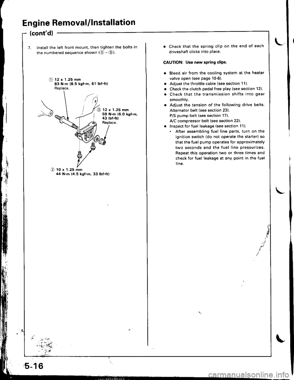
7. Install the left front mount, then tighten the bolts in
the numbered sequence shown (O - @).
O t2 x '1.25 mm83 N.m 18.5 kgt.m,61 lbl.ft)Fleplace.
@ 12 x 1.25 mm59 N.m 16.0 kgf.m,43 lbf.frlReplace.
O 10 x 1.25 mmil4 N.m 14.5 kgt'm,33 lbt.ft)
,5-16
. Check that the spring clip on the end of each
driveshaft clicks into place.
CAUTION: Use new spring clips.
. Bleed air {rom the cooling system at the heater
valve open (see page 10-6).
. Adjust the throttle cable (see section 1 1).
. Check the clutch pedalfree play (see section 12).
. Check that the transmission shifts into gear
smoothlY.
. Adjust the tension of the following drive belts.
Alternator belt {see section 23).
P/S pump belt (see section 171.
A/C comDressor belt (see section 22).
! Inspect for tuel leakage (see section 1ll.. After assembling fuel line parts, turn on the
ignition switch (do not operate the staner) so
that the fuel pump operates for approximately
two seconds and the fuel line pressurizes.
Repeat this operation two or three times and
check for tuel leakage at any point in the {uel
line.
Page 208 of 1681
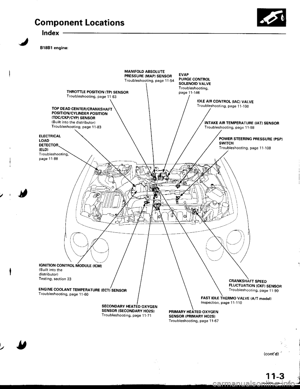
Component Locations
Index
81881 engine:
TOP DEAD CENTER/CRANKSHAFTPOSITION/CYLINDER POSITION{TDC/CKP/CYP' SENSOR(Built into the distributor)Troubleshooting, page I 1-83
ELECTRICALLOAO
Troubleshooting,page 11-88
MANIFOLD AsSOLUTEPRESSURE IMAP} SENSOFTroubleshooting, psge 1 '1,54EVAPPURGE CONTROLSOLENOID VALVETroubleshooting,page 11-146THROTTLE POSITION {TPI SENSORTroubleshooting, page 11 63
IELO}
IDLE AIR CONTROL IIAC) VALVETroubleshooting, page 1 1-1OO
CRANKSHAFT SPEEDFLUCTUATION {CKF} SENSORTroubJeshoonng. page 1t 90
FAST IDLE THERMO VALVE {A/T modet)Inspection, page 1'l 110
INTAKE AIR TEMPERATURE {IA1 SENSORTroubleshooting, page 1 'l -58
POWER STEERING PRESSURE IPSP}swtTcHTroubleshooting, page 1 1,108
IGNITION CONTROL{Built into thedistributorlTesting, section 23
ENGTNE cooLANT TEnapenerune {ectisensoaTroubleshooting, page 1 1 -60
SECONDARY HEATED OXYGENSENSOR (SECONDARY HO2SITroubleshooting, page 1 1-71PRIMARY HEATEO OXYGENSENSOR {PFIMARY HO2SITroubleshooting, page 1 1-67
lz
(cont'd)'
Page 209 of 1681
Component Locations
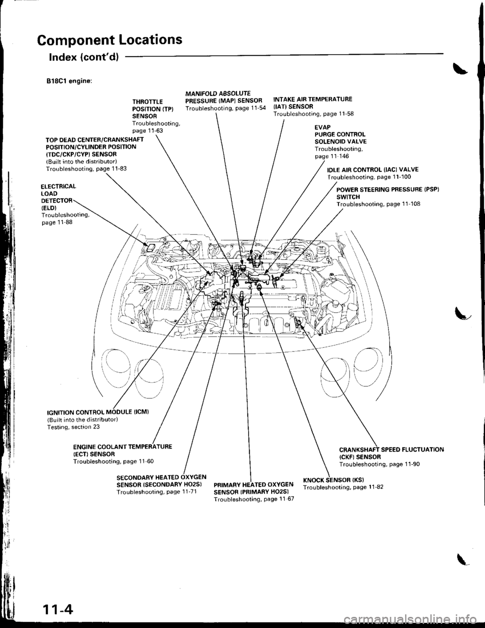
Index (cont'dl
B18C1 engine:
THROTTLEPOSITION (TP}
SENSORTroubleshooting,page 1 'l -63
MANIFOLD AESOLUTEPRESSURE IMAP) SENSORTroubleshooting, page 11_54
INTAKE AIR TEMPERATURE{IATI SENSORTroubleshooting, page 11'58
TOP DEAD CENTER/CRANKSHAFTPOSITION/CYLINOER POSITION
{TDC/CKP/CYP) SENSOR{BUilt into the distributor)Troubleshooting, page 1 1-83
EVAPPURGE CONTROLSOLENOID VALVETroubleshooting,page rr rqo
IDLE AIR CONTROL (IAC) VALVETroubleshooting, page 1 l-100
ELECTRICALLOAD
Troubleshooting,page 11 88
POWER STEERING PRESSURE IPSP}swtTcHTroubleshooting, page 'l1 108
IGNITION CONTROL
;- \
SENSOR {SECONDARY HO2S)
Troubleshooting, Page 1 1_71
(Built into the distributodTesting, section 23
ENGINE COOLANTIECD SENSORTroubleshooting, page 11 60
SECONDARY HEATED
SPEED FLUCTUATION(CKF) SENSORTroubleshooting, page 1 1-90
PRIMARY HEATED OXYGENKNOCK SENSOR IKSITroubleshooling, page 1 1_82SENSOR IPRIMARY HO2S)Troubleshooting, Page 11 67
il\
e)
11-4
Page 237 of 1681
t-
il
Troubleshooting ".
Troubleshooting Proccdures
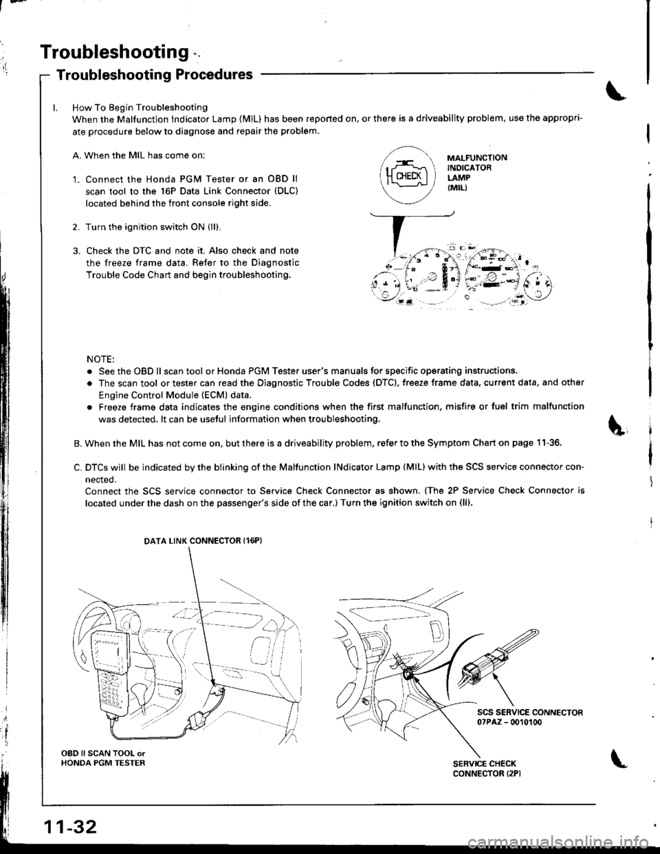
How To Begin Troubleshooting
When the Malfunction lndicator Lamp {MlL) has been reponed on, or there is a driveability problem, use the appropri-
ate procedure below to diagnose and repair the problem.
A. When the MIL has come on:
'1. Connect the Honda PGM Tester or an OBD ll
scan tool to the 16P Data Link Connector (DLC)
located behind the front console right side.
2. Turn the ignition switch ON (ll).
3. Check the DTC and note it. Also check and note
the freeze frame data. Refer to the Diagnostic
Trouble Code Chart and begin troubleshooting.
NOTE:
. SeetheOBDll scantool or Honda PGM Tester user's manuals for specific operating instructions.
. The scan tool or tester can read the Diagnostic Trouble Codes (OTC). freeze frame data, current data, and other
Engine Control Module (ECM) data.
. Freeze frame data indicates the engine conditions when the first malfunction, misfire or luel trim malfunction
was detected. lt can be useful information when troubleshooting.
B. When the MIL has not come on, but there is a driveability problem, refer to the Symptom Chart on page 11-36.
C. DTCS wjll be indicated by the blinking of the Malfunction lNdicator Lamp {MlL) with the SCS service connector con-
nected.
Connect the SCS service connector to Service Check Connector as shown. (The 2P Service Check Connector is
located under the dash on the passenger's side of the car,) Turn the ignition switch on (lll.
scs sERvlcE coNNEcToEo?PAZ - 0010100
MAI-FUNCTIONINDICATORLAMP{MIL)
DATA LINK CONNECTOR Il6PI
OBO ll SCAN TOOL orHONDA PGM TESTER
Page 238 of 1681
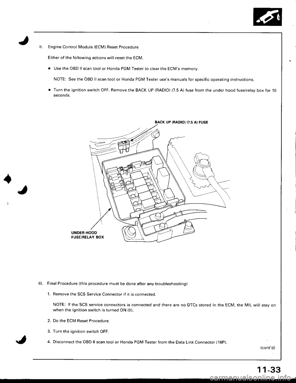
Engine Control Module (ECM) Reset Procedure
Either of the following actions will reset the ECM.
. Use the OBD ll scantool or Honda PGM Tester to clear the ECM'S memory.
NOTE: See the OBD ll scan tool or Honda PGM Tester use's manuals for specific operating instructions.
. Turn the ignition switch OFF. Remove the BACK UP (RADIO) (7.5 AI tuse from the under hood fuse/relay box for 10seconds.
BACK UP (RAOIO) {7.5 AI FUSE
UNDER'HOODFUSE/RELAY BOX
lll. Final Procedure (this procedure must be done after any trou bleshooting )
1. Remove the SCS Service Connector if it is connected.
NOTE: lf the SCS service connectors is connected and there are no DTCS stored in the ECM, the MIL will stav onwhen the ignition switch is turned ON (ll).
2. Do the ECM Reset Procedure.
3. Turn the ignition switch OFF.
4. Disconnect the OBD ll scan tool or Honda PGM Tester from the Data Link Connector (16P|.
{cont'd)
11-33
Page 239 of 1681
l7
Troubleshooting
Troubleshooting Procedures (cont'd)
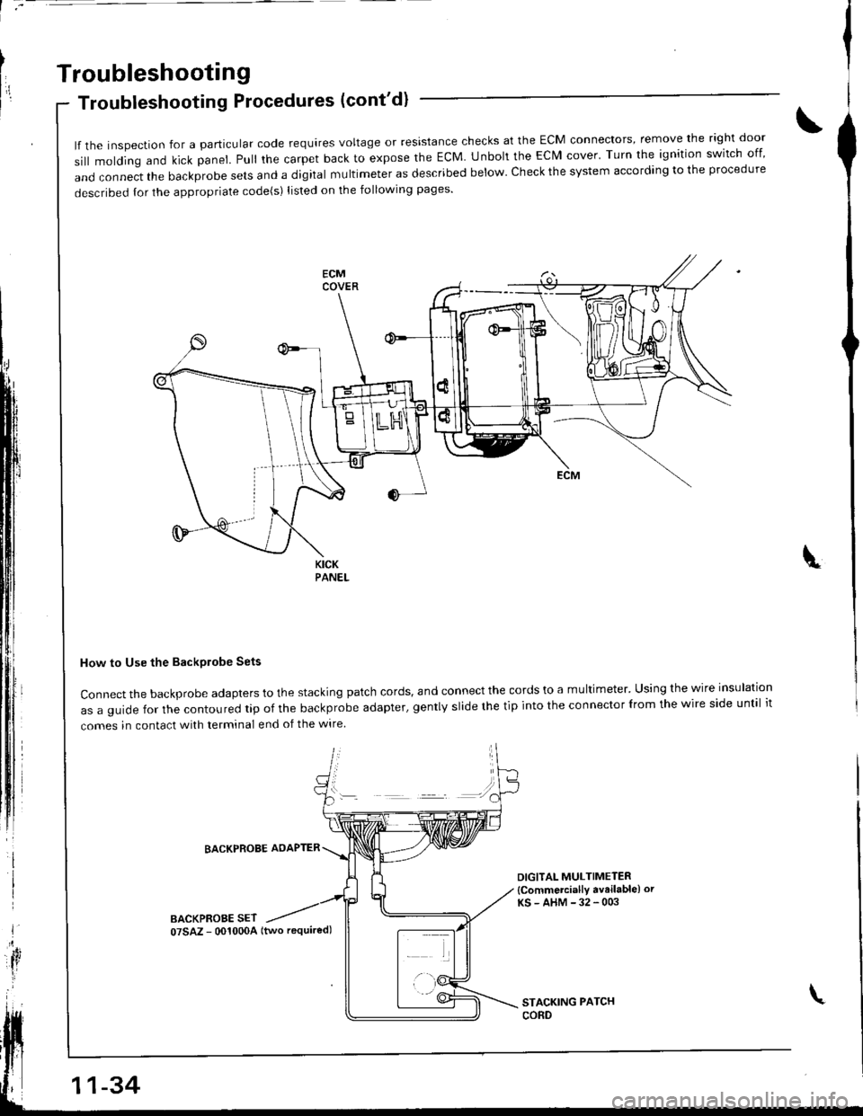
lf the inspection for a particular code requires voltage or resistance checks at the ECM connectors, remove the right door
sill molding and kick panel. pull the carpet back to expose the EcM. Unbolt the EcM cover. Turn the ignition switch off
and connect the backprobe sets and a digital multimeter as described below check the system according to the procedure
described {or the appropriate code(s) listed on the following pages'
How to Use the BackPlobe Sets
Connect the backprobe adapters to the stacking patch cords, and connect the cords to a multimeter' Using the wire insulation
as a guide for the contoured tip of the backprobe adapter, gently slide the tip into the connector lrom the wire side until it
comes in contact with terminal end of the wire
I
BACKPROBE AOAPTER
BACKPROBE SET
DIGITAL MULTIMETER
{Commetcially avrilable) or
KS-AHM-32-003
\
11-34
07SAZ - 001000A (two required)
Page 243 of 1681
Troubleshooting
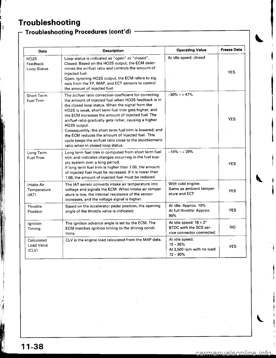
DataDescriotionOperating ValueFreeze Data
HO25
Feedback
Loop Status
Loop status is indicated as "open" or "closed".
Closed: Based on the H02S output, the ECM deter-
mines the airlfuel ratio and controis the amount of
iniected fuel.
Open: lgnoring HO2S output, the ECM refers to sig-
nals from the TP, MAP, and ECT sensors to control
the amount of iniected fuel.
Al idle speed: closed
YES
Short Term
Fuel Trim
The airlfuel ratio correclion coeificient lor correcting
the amount ol iniected fuel when HO2S feedback is in
the closed loop status. When the signal from the
HO2S is weak, short term fuel trim gets highef. and
the ECM increases the amount of injected fuel The
airlfuel ratio gradually gets richer, causing a higher
HO2S output.
Consequentlv, the short term fuel trim is lowered, and
the ECM reduces the amount of injected tuel. This
cycle keeps the airlfuel ratio close to the stoichiomeric
ratio when in closed loop status.
-30o/" - + 41%
YES
Term
Trim
Long
F uel
Long term fuel trim in computed trom short term fuel
trim and indicates changes occurring in the fuel sup-
ply system over a long period.
lf long term fuel trim is higher than 1.00, the amou nt
of injected fuel must be increased. ll it is lower than
1.00, the amount of iniected fuel must be reduced
-14% - + 2Oo/"
YES
lntake Air
Temperature(rAT)
The IAT sensor converts intake air temperature into
voltage and signals the ECM. When intake air temper-
ature is low, the internal resistance of the sensor
increases, and the voltage signal is higher.
With cold engine:
Same as ambient temPer-
ature and ECTYES
Throttle
Position
Based on the accelerator pedal position. the opening
anole of the throttle valve is indicated.
Ar idle: Approx. 107o
At full throttle: Approx.
90%
YES
lgnition
Timing
The ignition advance angle is set by the ECM. The
EClvl matches ignition timing to the driving condi-
tio ns.
At idle speed: 16 t 2'
BTDC with the SCS ser-
vice connector connected.
NO
Calculated
Load Value
(CLV)
CLV is the engine load calculated from the MAP data.At idle speedi
15 - 35%
At 2,500 rpm with no load:
12 - 30./.
YES
-38
Page 244 of 1681
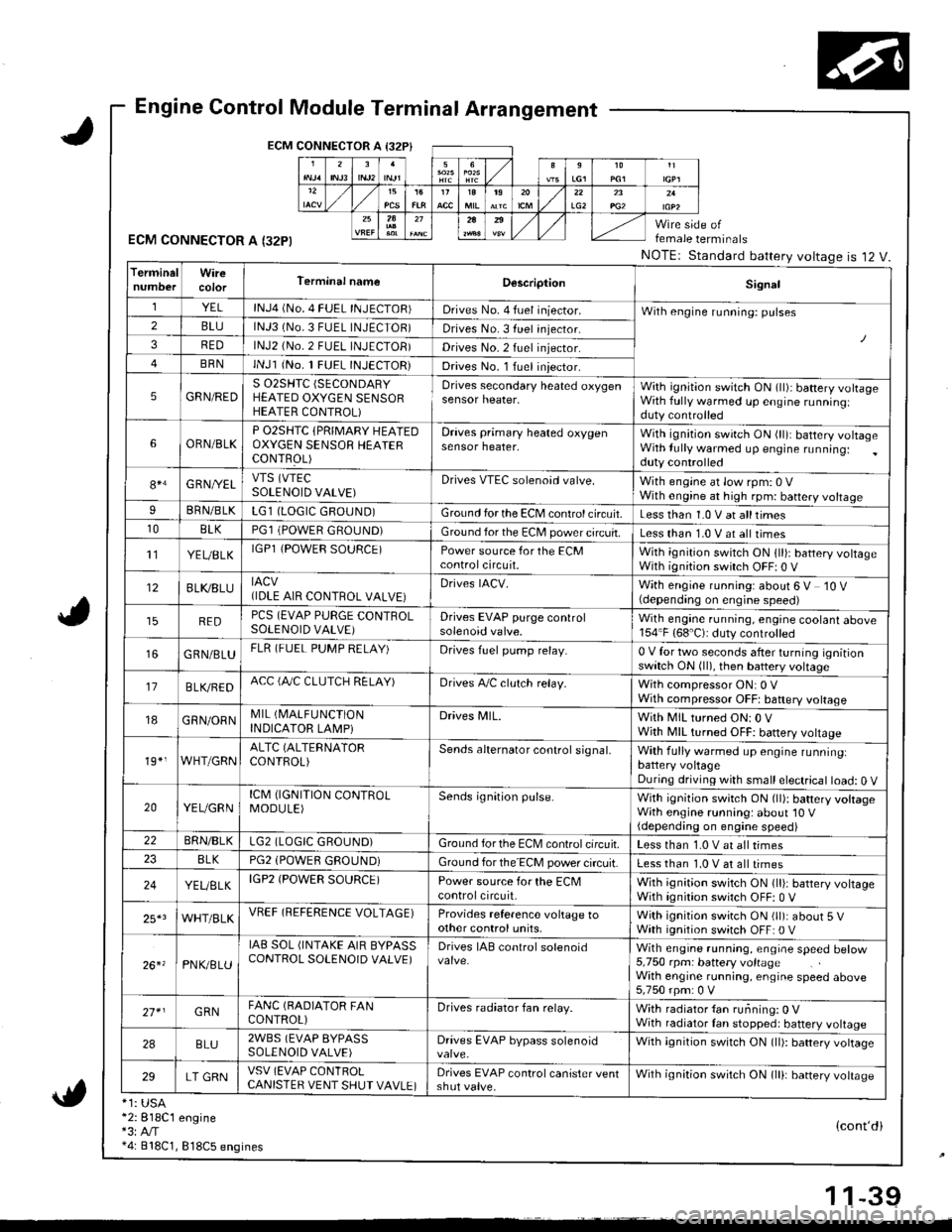
Engine Control Module Terminal Arrangement
ECM CONNECTOR A I32P}
ECM CONNECTOR A I32PI
*1: USA*2:818C1 engine*3:A,/T*4: 818C1, 818C5 engines
female terminals
NOTEr Standard battery voltageis 12 V.
{cont'di
LG22A
TerminalWireTerminal nameDescriptionSignal
YELlNJ4 (No. 4 FUEL INJECTOR)Drives No. 4 fuel iniector.With engine running: pulses2BLUlNJ3 (No.3 FUEL INJECTOR)Drives No. 3 fuel injector.
3REDlNJ2 (No.2 FUEL INJECTOB)Drives No.2 fuel injector.
BRNlNJl (No. 1 FUEL INJECTOR)Drives No. l Iuel iniector.
5GRN/REDS 02SHTC (SECONDARY
HEATED OXYGEN SENSORHEATER CONTROL)
Drives secondary heated oxygensensor heater,With ignition switch ON (ll)i battery volrageWith fully warmed up engine runningiduty controlled
6ORN/BLKP O2SHTC {PRIMARY HEAIEDOXYGEN SENSOB HEAIERCONTFOL)
Draves primary heated oxygensensor heater,With ignition swirch ON (ll): battery voltageWith lully warmed up engine running:duty controlled
84G RNI/ELVTS (VTEC
SOLENOID VALVE)Drives VTEC solenoid valve.With engine at low rpm: 0 VWith engine at high rpm: battery voltageIBRN/BLKLG1 (LOGIC GROUND)Ground for the ECM control circuit.Less than 1.0 V at alltimes10BLKPGl (POWER GROUND)Ground for the EC[, power circuit.Less than 1.0 V at all times't'lYEUBLKIGPl {POWER SOURCE)Power source for the ECMcontrolcircuit.With ignition switch ON 1ll): battery voltageWith ignition switch OFF| 0 V
12BLI(8LUIACV(IDLE AIR CONTROL VALVE}Drives IACV.With engine running: about 6 V 10 V(depending on engine speed)
REDPCS (EVAP PURGE CONTROLSOLENOID VALVE)Drives EVAP purge controlsolenoid valve.Wilh engane running, engine coolant above154"F (68'C): duty controlled
GRN/BLUFLR (FUEL PUMP RELAY)Drives fuel pump relay.0 V for two seconds after turning ignitionswitch ON (ll), then battery voltage
17B LVBEDACC (fuC CLUTCH RELAY)Drives A,/C clulch relay.With compressor ON: 0 VWith compressor OFFt baftery voltage
18GRN/ORNMIL (I\4ALFUNCTION
INDICATOR LAMPiDrives MlL.With MIL turned ON:0 VWjth MIL turned OFF: battery vottage
19*,WHT/GRNALTC (ALTERNATOR
CONTROL)Sends alternator control signal,With fully warmed up engine runninglbattery voltageDuring driving with small electrical load: 0 V
20YEUGRNICM (IGNITION CONTROLMODULE)Sends ignition pulse.With ignition switch ON (ll): battery voltageWith engine running: about'10 V(depending on engine speed)22BRN/BLKLG2 (LOGIC GROUND)Ground forthe ECM controlcifcuit.Less than 1.0 V at all times8LKPG2 (POWEfl GROUND)Ground for the ECM power circuit.Less than 1.0 V at all times
24YEUELKIGP2 (POWER SOURCE)Power source for the ECMcontrolcircuit,With ignition switch ON {lli: battery voltageWith ignition switch OFF: 0 V
25*3WHT/BLKVREF (REFERENCE VOLTAGE)Provides reference voltage toother control units,With ignition swirch ON (ll): about 5 VWath ignition switch OFF: 0 V
26. 'PNK/8LU
IAB SOL (INTAKE AIR BYPASSCONTROL SOLENOID VALVE)Drives IAB conlrol solenoidWith engrne running, engrae speed betow5,750 rpm: battery voltageWith engine running, engine speed above5,750 rpm: 0 V
27* IGRNFANC (BADIATOR FANCONTROL)Drives radiator fan relay.With radiator {an running: 0 VWith radiator Ian stopped: battery voltage
2ABLU2WBS (EVAP BYPASSSOLENOID VALVE)Drives EVAP bypass solenoidWith ignition switch ON (ll): battery vottage
29LT GRNVSV (EVAP CONlROLCANISTER VENT SHUT VAVLE)Drives EVAP control canister ventshut valve.Wilh ignilion switch ON lll): banery votrasc
1 1-39
Page 245 of 1681
I
t
h,,l,!
il
Troubleshooting
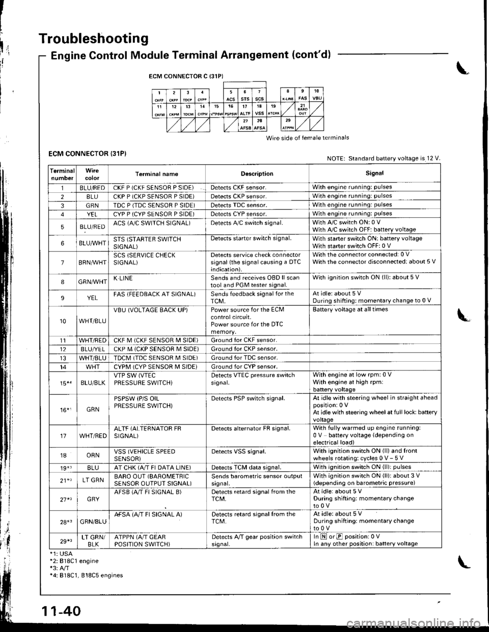
ECM CONNECTOR {31P)
Engine Control Module Terminal Arrangement (cont'd)
ECM CONNECTOR C {31P)
235srsscs1112t31515t71A19
2A
Wire side of lemale terminals
NOTE: Standard battery voltage is 12 V.
TerminalnumbercolorTerminal namoD6scriptionSignal
1BLU/REDCKF P (CKF SENSOR P SIDE)Detects CKF sensor.With engine running: pulses
28LUCKP P (CKP SENSOR P SIDE)Detects CKP sensor.With engine running: pulses
3GRNTDC P {TDC SENSOR P SIDE)Detects TDC sensor,With engine running: pulses
YELCYP P (CYP SENSOR P SIDE)Detects CYP sensor,With engine running: pulses
5BLU/REDACS (AJC SWITCH SIGNAL)Detects A,/C switch signal.With A,/C switch ON: 0 VWith A,/C switch OFF: battery voltage
6BLUA/VHTSTS (STARTEB SWITCHSIGNAL)
Detects starter switch signal.With staner switch ON: battery voltageWith starter switch OFF: 0 V
7BRN,AiVHTSCS (SERVICE CHECKSIGNAL)Detects service check connectorsignal (the signalcausing a DTC;ndication).
With the co n nector con nected: 0 VWath the connector disconnected: about 5 V
8GRNAVHTK LINESends and receives OBD ll scantool and PGM tester signal.With ignition switch ON (ll): about 5 V
9YELFAS lFEEDBACK AT SIGNAL)Sends feedback signal for theTCM,At idle: about 5 VDuring shifting: momenlary change to 0 V
10WHT/BLU
VBU (VOLTAGE BACK UP)Power source for the ECMcontrolcircuit,Power source for the DTC
Battery voltage at all times
t1WHT/REDCKF M (CKF SENSOR I\4 SIDE)Ground for CKF sensor.
12BLUI/E LCKP M (CKP SENSOR M SIDE)Ground for CKP sensor.
WHT/BLUTDCM (TDC SENSOR M SIDE)Ground tor TDC sensor.
14CYPM (CYP SENSOR M SIDE)Ground for CYP sensor.
15*.BLU/BLKVTP SW (VTEC
PRESSUFE SWITCH)Detects VTEC pressure switchsr9nal.
With engine at low rpm:0 VWith engine at high rpmlbattery voltaqe
161,GRN
PSPSW (P/S OILPRESSURE SWITCH)Derecls PSP switch signal.At idle with steering wheel in straight aheadpositioni 0 VAt idle with steering wheelat full lock: batteryvoltage
17WHT/REDALTF (ALTERNATOR FRSIGNAL)Detects alternator FR signal.With fully warmed up engine running:0 V battery voltage (depending onelectrical load)
18ORNVSS (VEHICLE SPEEDSENSORiDetects VSS signal.With ignition switch ON (ll) and lrontwheels rotating: cycles 0 V- 5 V
19*3BLUAT CHK (A/T FI DATA LINE)Detects TCM data signal.With ignition switch ON (ll)i pulses
21*LT GRNBARO OUT (SAROMETRIC
SENSOR OUTPUT S!GNAL)Sends barometric sensor outputsrgnal,With ignition switch ON (ll): about 3 V(depending on barometric pressure)
27 x3GRYAFSB (A"/T FI SIGNAL B)Detects retard signal from theTCM,At idle: about 5 VDuring shifting: momentary changeto0V
28+1GRN/8LUA+SA (A/T FI SIGNAL A)Detects retard signal from theTCM.At idle: about 5 VDuring shifting: momentarV changeto0V
29+3LT GRN/BLKATPPN (A/T GEARPOSITION SWITCH)Detects A,/T gear position switchsrgnal-In E orE positionr 0VIn anv other position: battery voltage
*1: USA*2:818C1 engine*3: A/T*4: 818C1, 818C5 engines
Page 246 of 1681
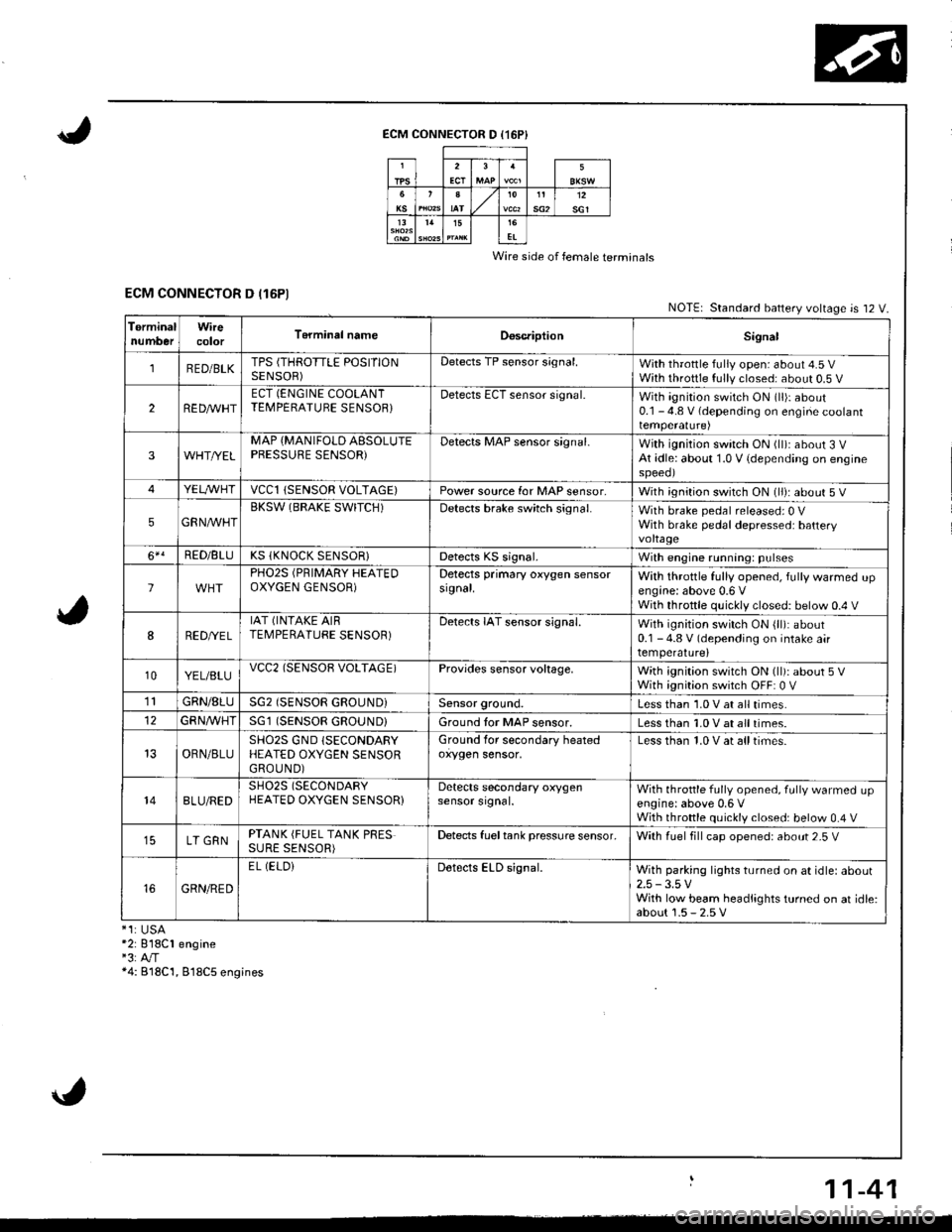
ECM CONNECTOR D (16P}
Wire side of female terminals
ECM CONNECTOR D (16P1NOTE| Standard battery voltage is 12 V.
TerminalnumberWirecolorT6rminal nameDoscriptionSignal
1RED/BLKTPS (THROTTLE POSITIONSENSOR)Detects TP sensor s;gnal.With throttle fully open: about 4.5 VWith throttle fully closed: about 0.5 V
2REDAr'r'HTECT (ENGINE COOLANTTEMPERATUBE SENSOB}Detects ECT sensor signal.With ignition switch ON (ll)r about0.1 - 4.8 V (depending on engine coolanttemperalure)
3WHT//ELMAP {MANIFOLD AESOLUTEPBESSURE SENSOR)Detects MAP sensor signal.With ignition switch ON (ll)iabout 3 VAt idle: about 1.0 V {depending on enginespeeol
4YELA/VHTvccl{SENSOR VOLTAGE)Power source for MAP sensor,With ignition switch ON (ll): about 5 V
5GRNAVHTBKSW (BRAKE SWITCH)Detects brake switch signal.With brake pedal released: 0 VWith brake pedal depressed: batteryvoltage
6*!RED/BLUKS (KNOCK SENSOR}Detects KS signal.With engine running: pulses
lPHO2S (PRIMARY HEATEDOXYGEN GENSOR)Detects primary oxygen sensorsignal.With throttle fully opened, fully warmed upengine: above 0.6 VWith throttle quickly closed: below 0.4 V
8RED/VEL
IAT (INTAKE AIRTEMPERATURE SENSOR)Detects IAT sensor signal.With ignition switch ON {ll): about0.1 - 4.8 V (depending on intake airtemperature)
10YEL/BLUvcc2(SENSOB VOLTAGE)Provides sensor voltage,With ignition switch ON (ll): about 5 VWith ignition switch OFF: 0 V
1lGRN/8LUSG2 (SENSOR GROUND}Sensor ground.Less than 1.0 V at all times.
GFNA/VHT(SENSOR GROUND}Ground tor MAP sensor.Less than 1.0 V at all times.
OBN/BLUSHO2S GND (SECONDARY
HEATED OXYGEN SENSORGROUND)
Ground for secondary heatedoxygen sensor,Less than 1.0 V at alltimes.
148LU/REDSH02S (SECONDARY
HEATED OXYGEN SENSOR}Detects secondary oxygensensor srgnal.With throttle fully opened. fully warmed upengine: above 0,6 VWith throttle quickly closed: below 0.4 V
LT GRNPTANK (FUEL TANK PRESSURE SENSOR)Detects fueltank pressure sensor.With luel fill cap opened: about 2-5 V
GRN/RED
EL (ELOiDetects ELD signal.With parking lights turned on at idle: about2.5 -3.5 VWith low beam headlights turned on at idle:about 1.5 - 2.5 V*1:USA*2: 818C1 engine"3:A"/T*4: B18C'1, 818C5 engines
11-41