parking sensors HONDA INTEGRA 1998 4.G Workshop Manual
[x] Cancel search | Manufacturer: HONDA, Model Year: 1998, Model line: INTEGRA, Model: HONDA INTEGRA 1998 4.GPages: 1681, PDF Size: 54.22 MB
Page 246 of 1681
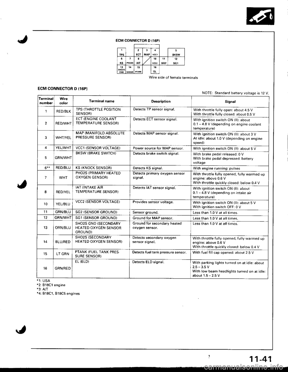
ECM CONNECTOR D (16P}
Wire side of female terminals
ECM CONNECTOR D (16P1NOTE| Standard battery voltage is 12 V.
TerminalnumberWirecolorT6rminal nameDoscriptionSignal
1RED/BLKTPS (THROTTLE POSITIONSENSOR)Detects TP sensor s;gnal.With throttle fully open: about 4.5 VWith throttle fully closed: about 0.5 V
2REDAr'r'HTECT (ENGINE COOLANTTEMPERATUBE SENSOB}Detects ECT sensor signal.With ignition switch ON (ll)r about0.1 - 4.8 V (depending on engine coolanttemperalure)
3WHT//ELMAP {MANIFOLD AESOLUTEPBESSURE SENSOR)Detects MAP sensor signal.With ignition switch ON (ll)iabout 3 VAt idle: about 1.0 V {depending on enginespeeol
4YELA/VHTvccl{SENSOR VOLTAGE)Power source for MAP sensor,With ignition switch ON (ll): about 5 V
5GRNAVHTBKSW (BRAKE SWITCH)Detects brake switch signal.With brake pedal released: 0 VWith brake pedal depressed: batteryvoltage
6*!RED/BLUKS (KNOCK SENSOR}Detects KS signal.With engine running: pulses
lPHO2S (PRIMARY HEATEDOXYGEN GENSOR)Detects primary oxygen sensorsignal.With throttle fully opened, fully warmed upengine: above 0.6 VWith throttle quickly closed: below 0.4 V
8RED/VEL
IAT (INTAKE AIRTEMPERATURE SENSOR)Detects IAT sensor signal.With ignition switch ON {ll): about0.1 - 4.8 V (depending on intake airtemperature)
10YEL/BLUvcc2(SENSOB VOLTAGE)Provides sensor voltage,With ignition switch ON (ll): about 5 VWith ignition switch OFF: 0 V
1lGRN/8LUSG2 (SENSOR GROUND}Sensor ground.Less than 1.0 V at all times.
GFNA/VHT(SENSOR GROUND}Ground tor MAP sensor.Less than 1.0 V at all times.
OBN/BLUSHO2S GND (SECONDARY
HEATED OXYGEN SENSORGROUND)
Ground for secondary heatedoxygen sensor,Less than 1.0 V at alltimes.
148LU/REDSH02S (SECONDARY
HEATED OXYGEN SENSOR}Detects secondary oxygensensor srgnal.With throttle fully opened. fully warmed upengine: above 0,6 VWith throttle quickly closed: below 0.4 V
LT GRNPTANK (FUEL TANK PRESSURE SENSOR)Detects fueltank pressure sensor.With luel fill cap opened: about 2-5 V
GRN/RED
EL (ELOiDetects ELD signal.With parking lights turned on at idle: about2.5 -3.5 VWith low beam headlights turned on at idle:about 1.5 - 2.5 V*1:USA*2: 818C1 engine"3:A"/T*4: B18C'1, 818C5 engines
11-41
Page 418 of 1681
Automatic Transmission
Special Tools ................ '14-2
Descraption .................... 14-3
Clutches ............ ...... 14-6
Power Flow ..,........... 14-8
Electronic Control System ..................... 1 4-1 8
Hydraulic Control ...... 14-23
Hydraulic Flow .........- 14-28
Lock-up System ........ 14-38
Electrical System
Component Location -................................ 1 4-45
Circuit Diagram ............. 14-46
TCM Terminal Voltage/
Measuring Conditions ......,.................... 1 4-48
Troubleshooting Procedures .. . ... ........ ...... ... 14-50
Symptom-to-Component Chart
Electrical System ...... 14-54
Electrical Troubleshooting
Troubleshooting Flowcharts .......... ... ...,.. 14-56
Lock-up Control Solenoid Valve A/B Assembly
Test .................. ...... 14-A7
Replacement ............. 14-a7
Shilt Control Solenoid Valve A/B Assembly
Test .................. ...... '14-88
Replacement .,..,........ 14-88
lvlainshaf t/Countershaft Speed Sensors
Replacement ....-......,. 14-89
Transmission Control Module (TCM)
Replacement ............. 14-89
Hydraulic System
Symptom-to-Component Chart
Hydraulic System ...... 14-90
Road Test ,................... 14-94
Stall Speed
Test .................. ...... 14-97
Fluid Level
Checking/Changing .... 14-98
Pressure Testing ........... 14-99
Transmission
Transmission
Removal ............. ...... 14-10�4
lllustrated lndex
Transmission/Right Side Cover ............... 1 4-1 08
Transmission Housin9 ................,..,....... 1 4-1'1 O
Torque Converter Housing/ValveBody .................. .. 14-112
Right Side Cover
Removal ............. ...... 14-114
Transmission Housing
Removal ............. ...... 14-1 l6
Torque Converter Housing/Valve Body
Removal ............. ...... l4-1 18
Valve Caps
Description ...........-... 14-120
Valve Body
Repair ................ ...... 14-12'l
Valve
Assembly
ATF Pump
Inspeclton
Main Valve Body
Disassembly/lnspection/Reassembly
Regulator Valve Body
Disassembly/lnspection/Reassembly
Lock-up Valve Body
Disassembly/lnspection/Reassembly
Secondary Valve Body
Disassembly/lnspection/Reassembly
Servo Body
....... 14-124
....... 14-126
....... 14-127
....... 14 124
Disassembly/lnspection/Reassembly .......
1st-hold Accumulator/Right Side Cover
Disassembly/lnspection/Reassembly .......
Mainsha{t
14-130
14-132
Disassembly/lnspection/Reassembly ....... 14-133
Inspection ................. 14-134
Countershaft
Disassembly/lnspection/Reassembly,..,.., l4-136
Disassembly/Reassembly ..,...,..,.........,,.. 1 4-1 37
Inspection ......,...,..,... 14-138
One-way Clutch
Disassembly/lnspection/Reassembly ....,.. 14-141
Sub-shaft
Disassembly/lnspection/Reassembly ...,,..'14-142
Disassembly/Reassembly ....................... 1 4- l 43
Sub-shaft Bearings
Replacement ,..,,.,,..,.. 14-144
Clutch
lllustrated Index ................................... I 4-1 45
Disassembly ............. 14-144
Reassembly .............. 14-150
Torque Converter Housing Bearings
Mainshaft Bearing/Oil Seal
Replacement ......... 14-154
Countershaft Bearing Replacement ......... 1 4- 1 55
Transmission Housing Bearings
Mainshaft/Countershaft BearingReplacement ......,.. 14-'156
Sub-shaft Bearing Replacement .,............ 1 4-1 57
Reverse ldler Gear
Installation .........-..... 14-158
Parking Brake Stop
Inspection/Adjustment .......................... 1 4-1 58
Transmission
Reassembly .............. 14-160
Torque Converler/Drive Plate ..............,.,,.,, 1 4-1 67
Transmission
Installation ............... 14-168
Cooler Flushing ......... 14-172
ATF Cooler Hoses
Connection ,..,,,....,,.,, '14-'174
*shift cable
Removal/lnstallation . . .. .... ... .... ... .... .. . ... .. 14-'l75
Adjustment ,..,...,,,,.,, 14-'116*Shilt lever
Disassembly/Reassembly ....................... 1 4-'17 7'Shift Indicator Panel
Adjustment .............. 14-178
\l
)g
Page 420 of 1681
Description
\J
t{
{
14-3
The automatic transmission is a combination of a 3-element torque converter and triple-shalt electronically controlled
automatic transmission which provides 4 speeds forward and 1 speed reverse. The entire unit is positioned in line with
the engrne.
Torque Converter, Gears, and Clutches
The torque converter consists of a pump, turbine, and stator, assembled in sigle unit. The torque converter is connected to
the engine crankshaft so they turn torether as a unit as the engine turns. Around the outside of the torque convener is a
ring gear which meshes with the starter pinion when the engine is being started. The entire torque converter assembly
serves as a flywheel while transmitting power to the transmission mainshaft.
The transmission has three parallel shafts; the mainshaft. the countershaft, and the sub shaft. The mainshaft is in-line with
the engine crankshaft.
The mainshaft includes the 1st, and 2ndl4th clutches,and gear for 3rd, 2nd, 4th, reverse, and 1st. (3rd gear is integral with
the mainshaft, while reverse gear is integral with the 4th gear.)
The countershaft includes the 3rd clutch and gears for 3rd,2nd, 4th, reverse, 1st, and parking. Reverse and 4th gears can
be loched to the countershaft at its center,providing 4th gear or reverse, depending on which way the selector is moved.
The sub-shaft includes the 1st-hold clutch and gears fo 1st and 4th.
The gears on the mainshaft are in constant mesh with those on the countersahft and sub-shaft.When certain combinations
of gears in the transmission are engaged by clutches. power in transmitted from the mainshaft to the countershaft via the
sub-shaft to orovude oil, lo'1. E, E. and E.
Electronic Control
The electronic control svstem consists of the Transmission Control Module (TCM), sensors, and four solenoid valves.
Shilting and lock-up are electronically controlled for comfortable driving under all conditions.
The TCM is located below the dashboard, behind the lelt side kick panel on the driver's side.
Hydraulic Control
The valve bodies include the main valve body, the secondary valve body, the regulator valve body, the serbvo body, and
the lock-up valve body, through the respective separator plates, They are bolted to the torque converter housing,
The main valve body contains the manual valve, the 1-2 shift valve, the 2-3 shitt valve, the Clutch Pressure Control
lCPC) valve, the 4th exhaust valve, the reliel valve, and the ATF pump gears.
The secondary valve body contains the 4-3 kick-down valve, the 3-2 kick-down valve, the 2-3 orifice control valve, the
3-4 shift valve, the orilice control valve, the modulator valve, and the servo control valve.
The regulator valve body contains the pressure regulator valve, the lock-up control valve, the torque converter check
valve, and the cooler check valve.
The servo body contains the servo valve, which is integrated with shift fork shaft, the throttle valve B, and the accumula-
tors.
The lock-up valve body contains the lock-up shift valve and the lock-up timing B valve, and is bolted to the regulator valve
ooqy.
Fluid from the regulator passes through the manual valve to the various control valves.
Shift Control Mechanism
Input to the TCM from various sensors located throughout the car determines which shift control solenoid valve should
be activated. Activating a shitt control solenoid valve changes modulator pressure, causing a shift valve to move. This
pressurizes a line to one ol the clutches, engaging that clutch and its corresponding gear.
Lock-uD Mechanism
In @ position, in 2nd, 3rd and 4th, and @ position in 3rd, pressurized fluid can be drained lrom the back oI the tor-
que converter through a fluid passage, causing the lock-up piston to be held against the torque converter cover. As this
takes place, the mainshaft rotates at the same speed as the engine crankshaft. Together with hydraulic control, the TCM
optimizes the timing of the lock-up mechanism.
The lock-up valves controlthe range of lock-up according to lock-up control solenoid valves A and B, and throttle valve B.
When lock-up control solenoid valves A and B activate, modulator pressure changes. Lock-up control solenoid valves
A and B are mounted on the torque converter housing, and are controlled by the TCM.
(cont'd)
Page 1406 of 1681
Ground-to-Components I ndex
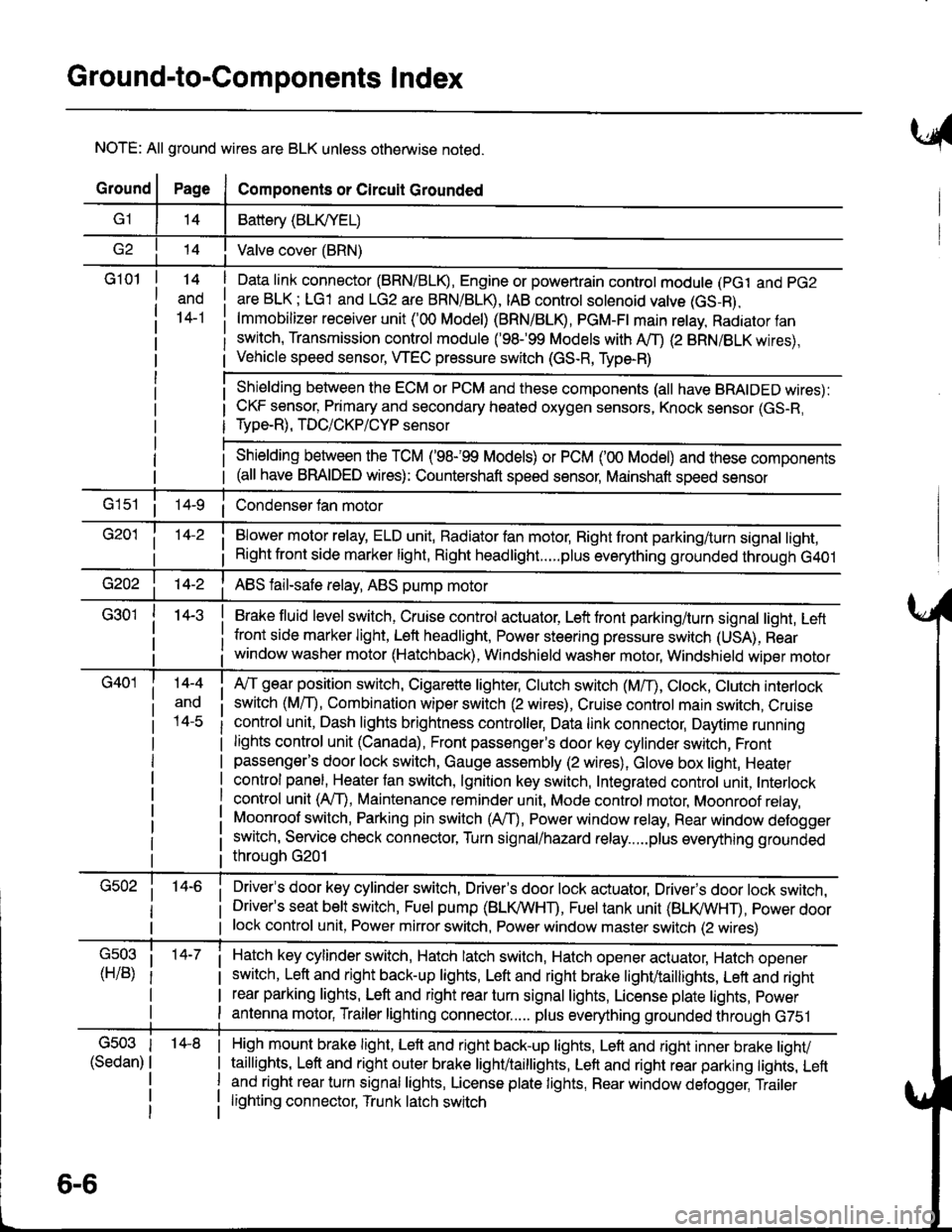
NOTE: All ground wires are BLK unless otherwise noted.
GroundPageComponents or Circuit Grounded
Battery (BLIVYEL)
--t'I Valve cover (BRN)
G101t.+
and
14-1
Daia link connector (BRN/BLK), Engine or powertrain controt module (pct and pG2
are BLK; LG1 and LG2 are BRN/BLR, IAB controt solenoid valve (GS-B),
lmmobilizer receiver unit ('00 Model) (BRN/BLR, PGM-Ft main retay, Radiator fan
switch, Transmission control module ('98.�99 Models with MD (2 BRN/BLK wires),
Vehicle speed sensor, WEC pressure switch (GS-R, Type-R)
Shielding between the ECM or PCM and these components (all have BRAIDED wires):
CKF sensor, Primary and secondary heated oxygen sensors, Knock sensor (GS-R,
Type-R), TDC/CKP/CYP sensor
Shielding between the TCM ('98-'99 Models) or PCM ('00 Model) and these components(all have BRAIDED wires): Countershaft speed sensor, Mainshaft speed sensor
G1s1 ii Condenser fan motor
Brake fluid level switch, Cruise control actuator, Left front parking/turn signal light, Left
front side marker light, Left headlight, Power steering pressure switch (USA), Rear
window washer motor (Hatchback), Windshield washer motor, Windshield wiper motor
14-3
Blower motor relay, ELD unit, Badiator fan motor, Right front parking/turn signal light,
Right front side marker light, Right headlight.....plus everything grounded through G401
ABS fail-safe relay, ABS pump motor
G40114-4
ano
l4-c
A,/T gear position switch, Cigarette lighter, Clutch switch (M,/T), Ctock, Ctutch interlock
switch (MfD, Combination wiper switch (2 wires), Cruise control main switch, Cruise
control unit, Dash lights brightness controller, Data link connector, Daytime running
lights control unit (Canada), Front passenger's door key cylinder switch, Frontpassenger's door lock switch, Gauge assembly (2 wires), Glove box light, Heater
control panel, Heater tan switch, lgnition key switch, Integrated control unit, Interlock
control unit (AfI), Maintenance reminder unit, Mode control motor, Moonroof relay,
Moonroof switch, Parking pin switch (AfD, Power window relay, Rear window defogger
switch, Service check connector, Turn signal/hazard relay.....plus everything grounded
throuoh G201
Driver's door key cylinder switch, Driver's door lock actuator, Drivels door lock switch,Driver's seat belt switch, Fuel pump (BLI(/WHT), Fuel tank unit (BLI(/WHT), power doorlock control unit, Power mirror switch, Power window master switch (2 wires)
Hatch key cylinder switch, Hatch latch switch, Hatch opener actuator, Hatch ooener
switch, Left and right back-up lights, Left and right brake light/taillights, Lett and right
rear parking lights, Left and right rear turn signal lights, License plate lights, power
antenna motor, Trailer lighting connector..... plus everything grounded through G751
6-6
'14-8G503
(Sedan)
High mount brake light, Left and right back-up lights, Lett and right inner brake tighv
taillights, Left and right outer brake light/taittights, Left and right rear parking tights, Leftand right rear turn signal lights, License plate lights, Rear window detogger, Trailer
lighting connector, Trunk latch switch
Page 1554 of 1681
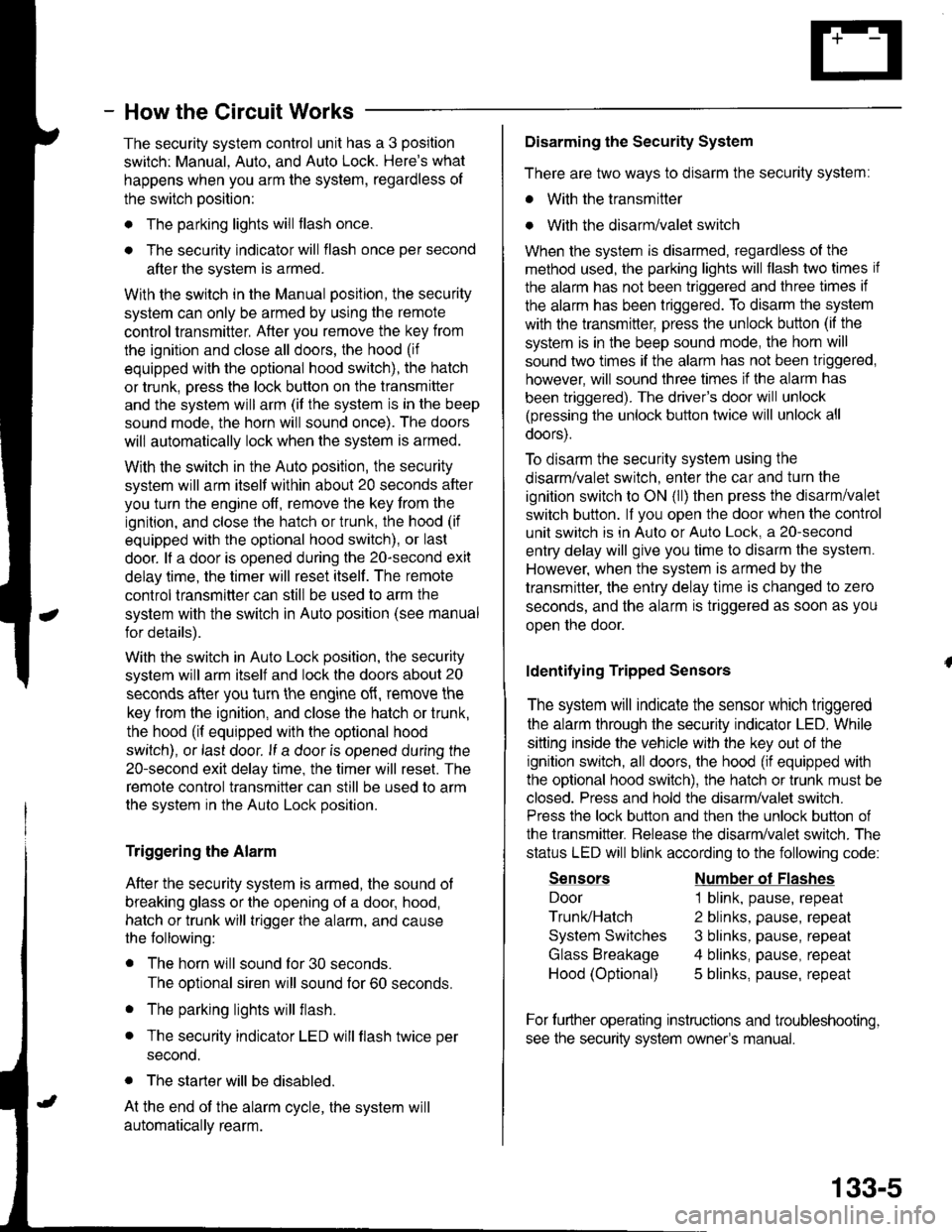
- How the Circuit Works
The security system control unit has a 3 position
switch: Manual. Auto. and Auto Lock. Here's what
happens when you arm the system, regardless ol
the switch position:
o The parking lights will flash once.
. The security indicator will flash once per second
after the system is armed.
With the switch in the Manual position, the security
system can only be armed by using the remote
control transmitter, After you remove the key from
the ignition and close all doors, the hood (if
equipped with the optional hood switch), the hatch
or trunk. Dress the lock button on the transmitter
and the system will arm (if the system is in the beep
sound mode, the horn will sound once). The doors
will automatically lock when the system is armed.
With the switch in the Auto position, the security
system will arm itself within about 20 seconds after
you turn the engine off, remove the key from the
ignition, and close the halch or trunk, the hood (if
equipped with the optional hood switch), or last
door. lf a door is opened during the 2o-second exit
delay time, the timer will reset itself . The remote
control transmitler can still be used to arm the
system with the switch in Auto position (see manual
for details).
With the switch in Auto Lock position, the security
system will arm itself and lock the doors about 20
seconds after you turn the engine of{, remove the
key from the ignition, and close the hatch or trunk,
the hood (if equipped with the optional hood
switch), or last door. lf a door is opened during the
2o-second exit delay time, the timer will reset. The
remote control transmitter can still be used to arm
the system in the Auto Lock position.
Triggering the Alarm
After the security system is armed, the sound ot
breaking glass or the opening of a door, hood,
hatch or trunk will trigger the alarm, and cause
the following:
r The horn will sound for30 seconds.
The optional siren will sound lor 60 seconds.
. The parking lights will flash.
. The security indicator LED will flash twice per
second.
. The starter will be disabled.
At the end of the alarm cycle, the system will
automatically rearm.
Disarming the Security System
There are two ways to disarm the security system:
. With the transmitter
o With the disarm/valet switch
When the system is disarmed, regardless of the
method used, the parking lights will flash two times if
the alarm has not been triggered and three times if
the alarm has been triggered. To disarm the system
with the transmitter, press the unlock button (if the
system is in the beep sound mode, the horn will
sound two times if the alarm has not been triggered,
however, will sound three times if the alarm has
been triggered). The driver's door will unlock
(pressing the unlock button twice will unlock all
doors).
To disarm the security system using the
disarm/valet switch, enter the car and turn the
ignition switch to ON (ll) then press the disarm/valet
switch button. lf you open the door when the control
unit switch is in Auto or Auto Lock, a 2o-second
entry delay will give you time to disarm the system.
However, when the system is armed by the
transmitter, the entry delay time is changed to zero
seconds, and the alarm is triggered as soon as you
oDen the door.
ldentifying Tripped Sensors
The system will indicate the sensor which triggered
the alarm through the security indicator LED. While
sitting inside the vehicle wlth the key out of the
ignition switch, all doors, the hood (if equipped with
the optional hood swilch), the hatch or trunk must be
closed. Press and hold the disarm/valet switch.
Press the lock button and then the unlock button of
the transmitter. Belease the disarm/valet switch. The
status LED will blink according to the following code:
Sensors
Door
Trunk/Hatch
System Switches
Glass Breakage
Hood (Optional)
Number ol Flashes
1 blink, pause, repeat
2 blinks, pause, repeat
3 blinks, pause, repeat
4 blinks, pause, repeat
5 blinks, pause, repeat
For further operating instructions and troubleshooting,
see the security system owner's manual.
133-5