HONDA PRELUDE 1992 Owners Manual
Manufacturer: HONDA, Model Year: 1992, Model line: PRELUDE, Model: HONDA PRELUDE 1992Pages: 225, PDF Size: 2.1 MB
Page 201 of 225
Identification Numbers
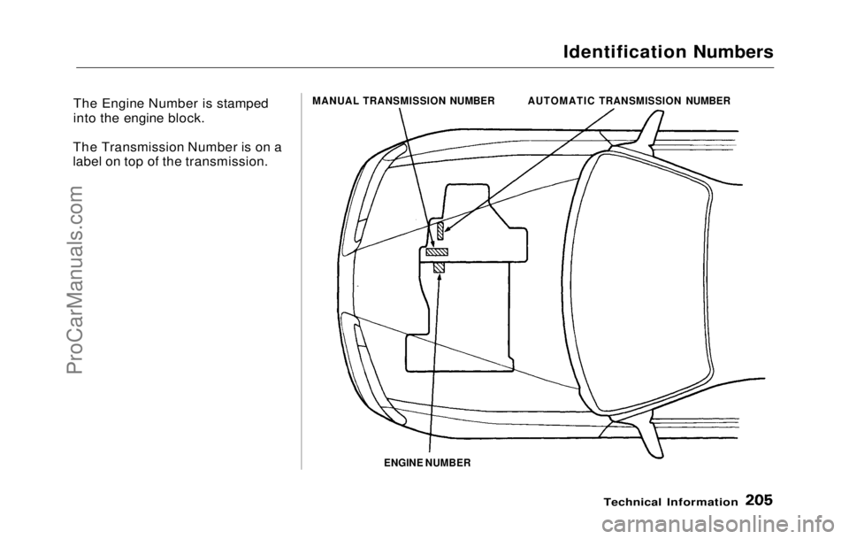
The Engine Number is stamped
into the engine block.
The Transmission Number is on a
label on top of the transmission.
ENGINE NUMBER
Technical Information
MANUAL TRANSMISSION NUMBER
AUTOMATIC TRANSMISSION NUMBERProCarManuals.comMain Menu Table of Contents s t
Page 202 of 225
Specifications
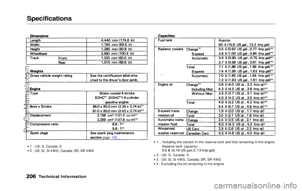
* 1 : US: S, Canada: S
* 2 : US: Si, Si 4WS, Canada: SR, SR 4WS *
1 : Including the coolant in the reserve tank and that remaining in the engine.
Reserve tank capacity:
0.6 (0.16 US gal,0.13 Imp gal)
* 2 : US: S, Canada: S
* 3 : US: Si, Si 4WS, Canada: SR, SR 4WS
* 4 : Excluding the oil remaining in the engine.
Technical Information
page 152ProCarManuals.comMain Menu Table of Contents s t
Page 203 of 225
Specifications
Technical Information
*
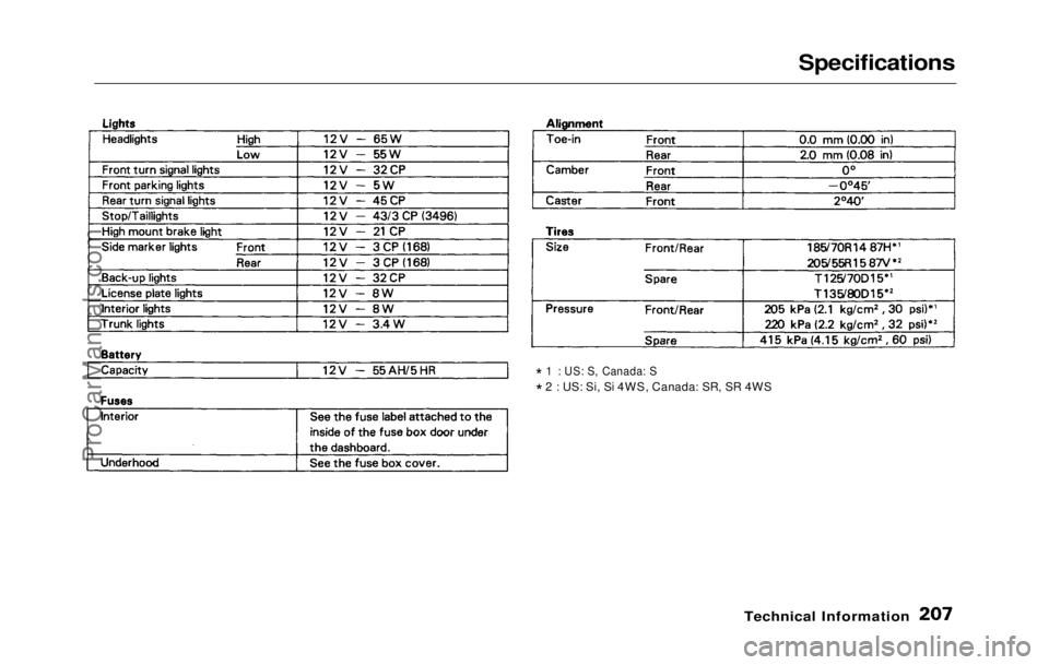
1 : US: S, Canada: S
* 2 : US: Si, Si 4WS, Canada: SR, SR 4WSProCarManuals.comMain Menu Table of Contents s t
Page 204 of 225
Anti-lock Brake System
The Anti-lock Brake System (ABS) is standard equipment on the
Prelude Si, Si 4WS sold in the U.S.
and SR, SR 4WS sold in Canada. It
is not available on any other models.
The ABS works by measuring how
fast the wheels are turning during
braking and comparing their speed.If any wheel is rotating much
slower than the others (on the
verge of locking up and skidding),
the system reduces hydraulicpressure to that wheel's brake
caliper. When that wheel's speed
matches the other wheels, the
system applies normal hydraulic pressure. This can take place
several times per second at each
wheel. You feel the ABS working as rapid pulsations in the brake
pedal.
Each wheel has a wheel speed
sensor assembly. As the wheel
rotates, the sensor sends electrical
pulses to the ABS control unit. The
pulse frequency varies with the
wheel speed.
The electrical output of the ABScontrol unit is connected to the
modulator/solenoid unit. During
braking, the ABS control unit monitors the pulse frequencies
from the four wheels. When the control unit detects a wheel locking
up, it energizes the appropriate
solenoid in the modulator/solenoid
unit. There are three solenoids: one
for each front wheel, and one for
the rear wheels. The energized solenoid reduces hydraulic pres-
sure to one side of a modulator
valve. This, in turn, reduces hydrau- lic pressure in the brake line going
to the affected wheel. When that
wheel speeds up because of the re- duced braking effort, the control unit de-energizes the solenoid. This
builds hydraulic pressure on the
modulator valve. The pressure in-
creases in the hydraulic line to the
wheel.
For the system to react quickly, the
modulator/solenoid unit must have
brake fluid under high pressure.
This is supplied by an accumulator
that is pressurized by an electric pump. A pressure-sensing switch
on the accumulator controls this
pump.
The control unit also contains error detection circuitry. It monitors the
operation of the wheel sensors, solenoids, pump, and electronics. If
the control unit detects any faults,
it shuts off power to the pump
motor and solenoids. The light on
the instrument panel comes on.
The brakes then work like a conventional system without anti-
lock capabilities.
Technical InformationProCarManuals.comMain Menu Table of Contents s t
Page 205 of 225
Supplemental Restraint System
The Honda
Supplemental Restraint
System (SRS) is standard on all
Preludes sold in the U.S. and the
SR, SR 4WS sold in Canada.
The SRS includes the steering
wheel airbag assembly, sensors in the dashboard, and a control unit
with sensors behind the center
console.
(On Si 4WS model)
The system also has a dashboard-
mounted airbag assembly for the
passenger.
The sensors are decelerometers,
set to trigger in a frontal impact that generates more force than a 10
mile per hour barrier crash. For the
SRS to activate, at least two sen-
sors must trigger. This duplication
is to prevent accidental activation. When the control unit receives
trigger signals from at least two
sensors, it sends voltage to the
airbag. The control unit stores this
charge in capacitors to insure
reliability even if a severe impact damages the car's battery or
electrical connections.
The electrical charge sent to the
airbag assembly ignites its propel-
lant, which burns instantaneously.
The gas produced by the burning propellant inflates the airbag in
about 40 milliseconds (1/25 of a
second).
The airbag is vented so it stays inflated for only an instant and
does not block the driver's vision.
Smoke from the burned propellant
comes out of the airbag and into
the car's interior. This is normal
and does not mean there is a fire.
The airbag collapses onto the driver's lap. The airbag unit can inflate only one
time. After use, your Honda dealer
must check the complete Supple-
mental Restraint System and re-
place the airbag assembly.
To ensure long-term reliability, the
SRS uses gold-plated electrical
connections throughout. Exposed
components are sealed with epoxy.
The control unit monitors the SRS circuitry whenever the ignition is
ON (II). If the control unit senses
any faults, it turns on the SRS
indicator light on the instrument
panel. Take the car to your Honda
dealer to diagnose and repair the system as soon as possible.
The SRS needs no regular mainte-
nance other than an inspection by
your Honda dealer ten years after
manufacture.
Technical InformationProCarManuals.comMain Menu Table of Contents s t
Page 206 of 225
Four Wheel Steering
The Si 4WS model in the U. S and
the SR 4WS model in Canada are
equipped with an electronic Four
Wheel Steering system.
As inputs, the 4WS system uses a
vehicle speed sensor and a sensor to measure how far the front
wheels are turned.
The electronic control unit for 4WS system uses these inputs to deter-
mine which direction to steer the
rear wheels, and at what angle. Depending on vehicle speed and the
angle of the front wheels, the rear
wheels will be "countersteered"
(steered in the opposite direction of
the front wheels) or "same-steered"
(steered in the same direction as
the front wheels). The 4WS electronic control unit
drives an electric motor built into
the rear steering box. Sensors for
rear wheel angle and speed provide
feedback. The electronic control
unit uses this feedback to compare
the actual rear wheel angle to the
desired angle.
When the driver turns the front
wheels with the car traveling less
than 18 mph (30 km/h), the rear
wheels are countersteered. The angle of countersteer increases as
the angle of the front wheels in-
creases, to a maximum counter-
steer angle of six degrees. This
improves response when parallel
parking or making sharp turns.
Above 18 mph (30 km/h), the rear
wheels are same-steered as the driver begins to turn the steering
wheel. The rear wheel angle for
any given steering wheel angle is
not fixed; it increases as vehicle speed increases. This improves
response in lane-changing maneu-
vers.
As the driver continues to turn the
steering wheel, the rear wheels are
steered back to the straight-ahead
position and then to countersteer
mode. As with same steer, the
angle of countersteer varies with
vehicle speed; increasing and then decreasing as the speed rises. This
gives improved handling in low, medium, and high speed curves.
The 4WS system's electronic
control unit monitors the sensors
whenever the ignition is ON. If it detects a problem anywhere in the
system, it lights the 4WS indicator
on the instrument panel and turns
the system off. With the system off,
the rear wheels remain pointed
straight ahead. Your car will then
drive like a conventional car
without 4WS.
Technical InformationProCarManuals.comMain Menu Table of Contents s t
Page 207 of 225
Emission Controls
The burning of gasoline in your
car's engine produces several by-
products. Some of these are carbon
monoxide (CO), oxides of nitrogen
(NOx) and hydrocarbons (HC).
Gasoline evaporating from the tank
also produces hydrocarbons. Con-
trolling the production of NOx, CO,
and HC is important to the environ-
ment. Under certain conditions of
sunlight and climate, NOx and HC
react to form photochemical "smog."
Carbon monoxide does not contri-
bute to smog creation, but it is a
poisonous gas.
The Clean Air Act
The United States Clean Air Act*
sets standards for automobile
emissions. It also requires that
automobile manufacturers explain
to owners how their emission
controls work and what to do to
maintain them. This section
summarizes how the emission con-
trols work. Scheduled maintenance
is on page 129 .
* In Canada, Honda vehicles
comply with the Canadian Motor
Vehicle Safety Standards (CMVSS)
for Emissions valid at the time they
are manufactured.
Crankcase Emission Control
System
Your car has a Positive Crankcase
Ventilation (PCV) System. This
keeps gasses that build up in the engine's Crankcase from going into
the atmosphere. The PCV valve
routes them from the crankcase
back to the intake manifold. They
are then drawn into the engine and
burned.
Evaporative Emission
Control SystemAs gasoline evaporates in the fuel
tank, a canister filled with charcoal
adsorbs the vapor. It is stored in
this canister while the engine is off.
After the engine is started and
warmed up, the vapor is drawn into the engine and burned during
driving.
Technical Informatio n
ProCarManuals.comMain Menu Table of Contents s t
Page 208 of 225
Emission Controls
Exhaust Emission Controls
The exhaust emission controls
include four systems: PGM-FI,
Ignition Timing Control, Exhaust
Gas Recirculation and Catalytic
Converter. These four systems
work together to control the engine's combustion and minimize
the amount of HC, CO, and NOx
that comes out the tailpipe. The
exhaust emission control systems
are separate from the crankcase
and evaporative emission control
systems.
PGM-FI System
The PGM-FI System on your car
has three sub systems: Air Intake,
Electronic Control, and Fuel
Control. The Electronic Control
Unit (ECU) uses various sensors to
determine how much air is going
into the engine. It then controls
how much fuel to inject under all
operating conditions. Ignition Timing Control System
This system constantly adjusts the
ignition timing, reducing the
amount of HC, CO and NOx
produced.
Exhaust Gas Recirculation (EGR)
The EGR system takes some of the
exhaust gas and routes it back into
the intake manifold. Adding ex-
haust gas to the air/fuel mixture re-
duces the amount of NOx produced
when the fuel is burned.
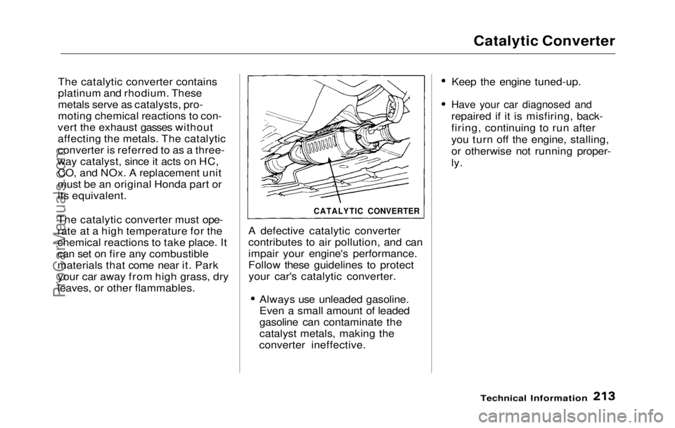
Catalytic Converter
The catalytic converter is in the exhaust system. Through chemical
reactions, it converts HC, CO, and
NOx in the engine's exhaust to
carbon dioxide (CO 2), dinitrogen
(N 2), and water vapor.
Replacement Parts
The emission control systems are
designed and certified to work to-
gether in reducing emissions to
levels that comply with the Clean
Air Act. To make sure the emis-
sions remain low, you should use
only new genuine Honda replace-
ment parts or their equivalent for
repairs. Using lower quality parts
may increase the emissions from
your car .
The emissions control systems are
covered b y
warranties separate
from the rest of your car. Read
your warranty manual for more
information.
Technical InformationProCarManuals.comMain Menu Table of Contents s t
Page 209 of 225
Catalytic Converter
The catalytic converter contains
platinum and rhodium. These
metals serve as catalysts, pro-
moting chemical reactions to con-
vert the exhaust gasses without
affecting the metals. The catalytic
converter is referred to as a three-
way catalyst, since it acts on HC, CO, and NOx. A replacement unit
must be an original Honda part or
its equivalent.
The catalytic converter must ope-
rate at a high temperature for the
chemical reactions to take place. It
can set on fire any combustible
materials that come near it. Park your car away from high grass, dry
leaves, or other flammables. A defective catalytic converter
contributes to air pollution, and can
impair your engine's performance.
Follow these guidelines to protect
your car's catalytic converter.
Always use unleaded gasoline.
Even a small amount of leaded
gasoline can contaminate the
catalyst metals, making the
converter ineffective. Keep the engine tuned-up.Have your car diagnosed and
repaired if
it is misfiring, back-
firing, continuing to run after
you turn off the engine, stalling,
or otherwise not running proper-
ly.
Technical Information
CATALYTIC CONVERTERProCarManuals.comMain Menu Table of Contents s t
Page 210 of 225
Warranty and Customer Relations
Warranty Coverages....................
216
Customer Relations
Information...............................
. 217
U.S. Zone Office Map.................. 218
Canada Zone Office Map ............ 219
Authorized Manuals.................... 221
Warranty and Customer RelationsProCarManuals.comMain Menu s t