HONDA RIDGELINE 2010 1.G Owner's Guide
Manufacturer: HONDA, Model Year: 2010, Model line: RIDGELINE, Model: HONDA RIDGELINE 2010 1.GPages: 421, PDF Size: 7.23 MB
Page 31 of 421
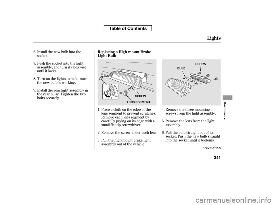
Remove the three mounting
screws f rom the light assembly.
Remove the lens f rom the light
assembly.
Pull the bulb straight out of its
socket. Push the new bulb straight
into the socket until it bottoms.
Place a cloth on the edge of the
lens segment to prevent scratches.
Remove each lens segment by
caref ully prying on its edge with a
small f lat-tip screwdriver.
Remove the screw under each lens.
Pull the high-mount brake light
assembly out of the vehicle.
Install the new bulb into the
socket.
Push the socket into the light
assembly, and turn it clockwise
until it locks.
Turn on the lights to make sure
the new bulb is working.
Install the rear light assembly in
the rear pillar. Tighten the two
bolts securely.
1. 2. 3. 4. 5.6.
6.7. 8. 9.
CONT INUED
Replacing a High-mount Brake
Light Bulb
Lights
Maint enance
341
LENS SEGMENT
SCREW SCREW
BULB
Table of Contents
Page 32 of 421
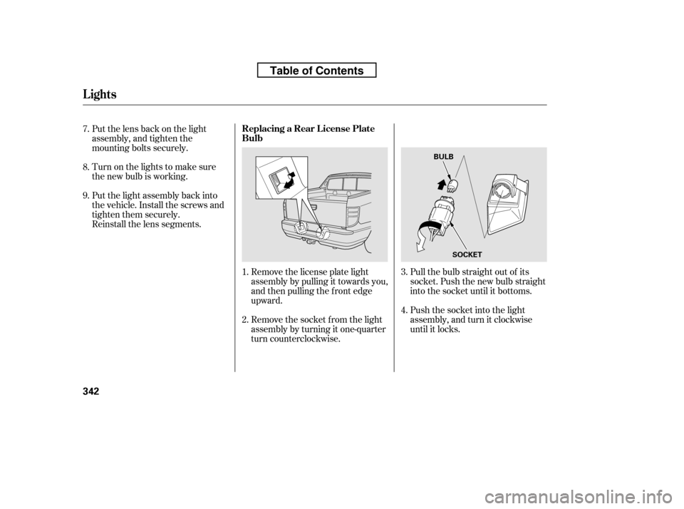
Pull the bulb straight out of its
socket. Push the new bulb straight
into the socket until it bottoms.
Push the socket into the light
assembly, and turn it clockwise
until it locks.
Remove the license plate light
assembly by pulling it towards you,
and then pulling the f ront edge
upward.
Remove the socket f rom the light
assembly by turning it one-quarter
turn counterclockwise.
Put the lens back on the light
assembly, and tighten the
mounting bolts securely.
Turn on the lights to make sure
the new bulb is working.
Put the light assembly back into
the vehicle. Install the screws and
tighten them securely.
Reinstall the lens segments.
1. 2. 3. 4.
8.
7. 9.
Lights
Replacing a Rear License Plate Bulb
342
BULB
SOCKET
Table of Contents
Page 33 of 421
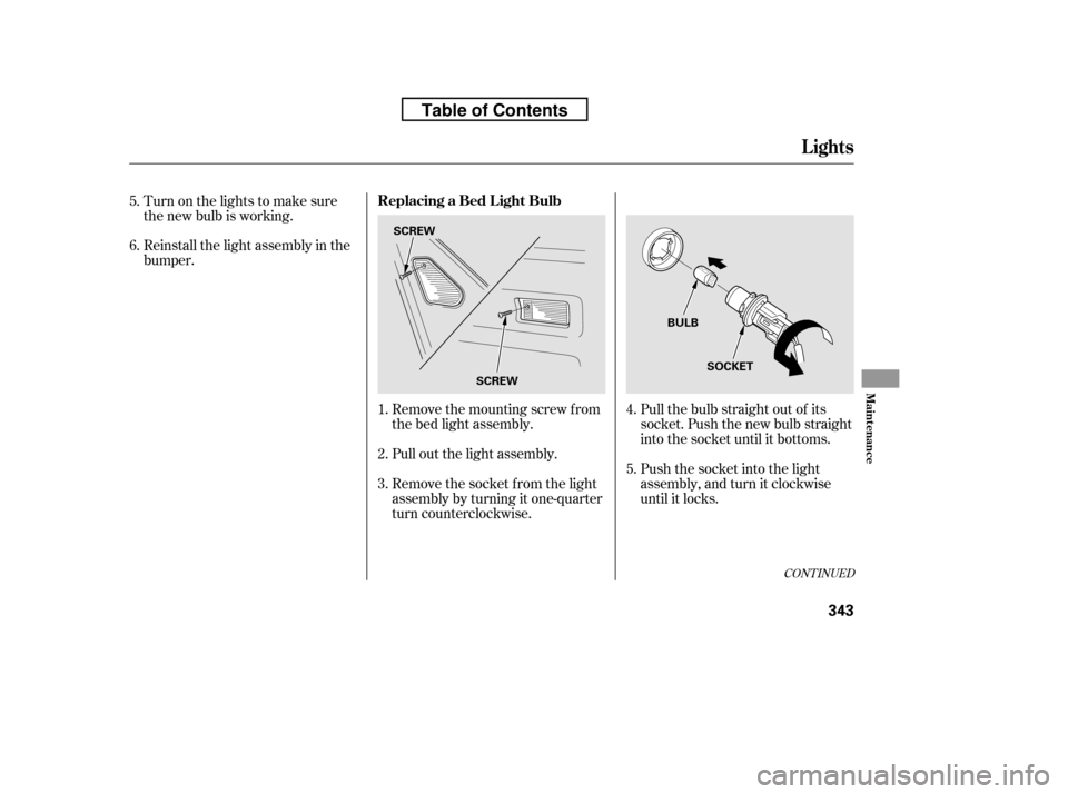
Pull the bulb straight out of its
socket. Push the new bulb straight
into the socket until it bottoms.
Push the socket into the light
assembly, and turn it clockwise
until it locks.
Remove the mounting screw f rom
the bed light assembly.
Pull out the light assembly.
Remove the socket f rom the light
assembly by turning it one-quarter
turn counterclockwise.
Turn on the lights to make sure
the new bulb is working.
Reinstall the light assembly in the
bumper.
1. 2. 3. 4. 5.
5. 6.
CONT INUED
Replacing a Bed L ight Bulb
Lights
Maint enance
343
SCREW
SCREW BULB
SOCKET
Table of Contents
Page 34 of 421
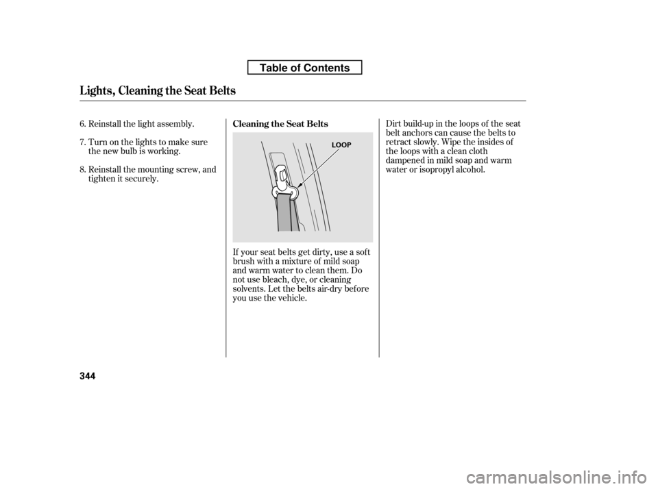
If your seat belts get dirty, use a sof t
brush with a mixture of mild soap
and warm water to clean them. Do
not use bleach, dye, or cleaning
solvents. Let the belts air-dry bef ore
you use the vehicle.Dirt build-up in the loops of the seat
belt anchors can cause the belts to
retract slowly. Wipe the insides of
the loops with a clean cloth
dampened in mild soap and warm
water or isopropyl alcohol.
Reinstall the light assembly.
Turn on the lights to make sure
the new bulb is working.
Reinstall the mounting screw, and
tighten it securely.
6. 7. 8.
Cleaning the Seat Belts
Lights, Cleaning the Seat Belts
344
LOOP
Table of Contents
Page 35 of 421
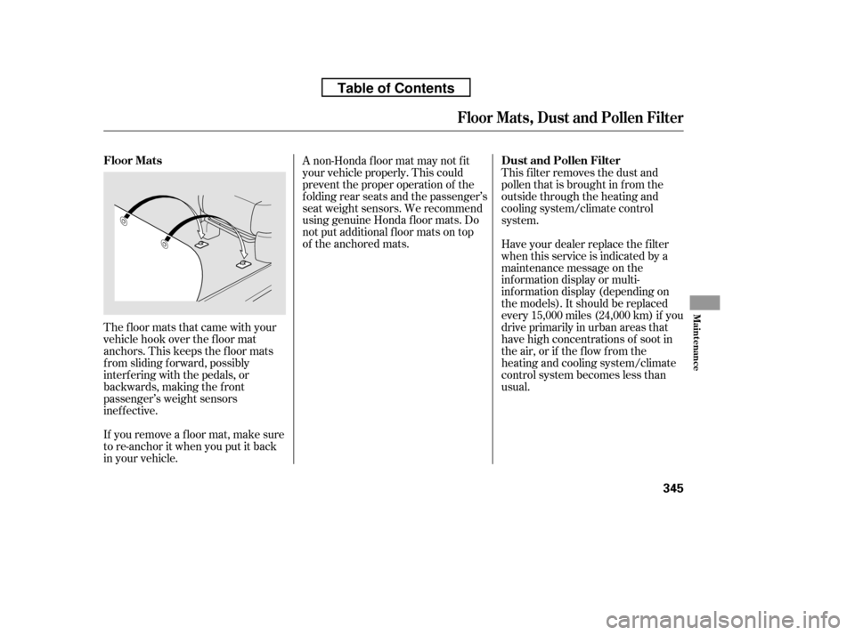
The floor mats that came with your
vehicle hook over the f loor mat
anchors. This keeps the f loor mats
f rom sliding f orward, possibly
interf ering with the pedals, or
backwards, making the f ront
passenger’s weight sensors
inef f ective.
If you remove a f loor mat, make sure
tore-anchoritwhenyouputitback
in your vehicle.A non-Honda f loor mat may not f it
your vehicle properly. This could
prevent the proper operation of the
f olding rear seats and the passenger’s
seat weight sensors. We recommend
using genuine Honda f loor mats. Do
not put additional f loor mats on top
of the anchored mats.
This f ilter removes the dust and
pollenthatisbroughtinfromthe
outside through the heating and
cooling system/climate control
system.
Have your dealer replace the filter
when this service is indicated by a
maintenance message on the
inf ormation display or multi-
inf ormation display (depending on
the models). It should be replaced
every 15,000 miles (24,000 km) if you
drive primarily in urban areas that
have high concentrations of soot in
the air, or if the flow from the
heating and cooling system/climate
control system becomes less than
usual.
Floor Mats, Dust and Pollen Filter
Floor Mats
Dust and Pollen Filter
Maint enance
345
Table of Contents
Page 36 of 421
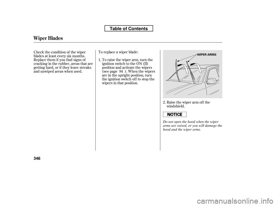
Raise the wiper arm of f the
windshield.
To replace a wiper blade:
To raise the wiper arm, turn the
ignition switch to the ON (II)
position and activate the wipers
(see page ). When the wipers
are in the upright position, turn
the ignition switch off to stop the
wipers in that position.
Check the condition of the wiper
blades at least every six months.
Replace them if you f ind signs of
cracking in the rubber, areas that are
getting hard, or if they leave streaks
and unwiped areas when used.
1.
2.
94
Wiper Blades
346
WIPER ARMS
Do not open the hood when the wiper
arms are raised, or you will damage the
hood and the wiper arms.
Table of Contents
Page 37 of 421
CONT INUED
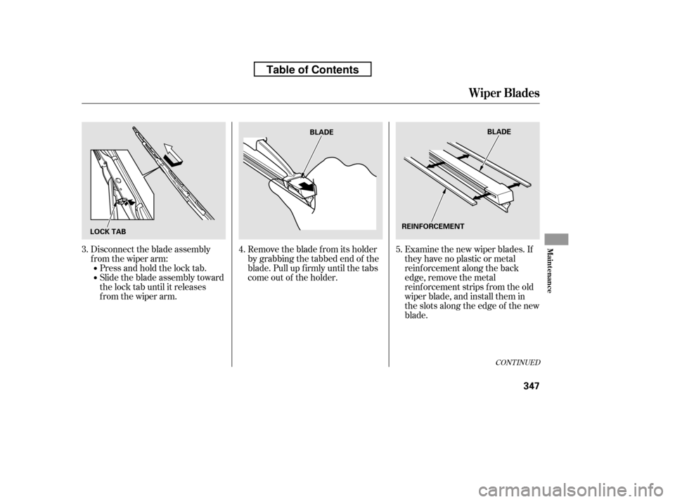
Remove the blade f rom its holder
by grabbing the tabbed end of the
blade. Pull up f irmly until the tabs
come out of the holder.Examine the new wiper blades. If
they have no plastic or metal
reinf orcement along the back
edge, remove the metal
reinf orcement strips f rom the old
wiper blade, and install them in
the slots along the edge of the new
blade.
Disconnect the blade assembly
from the wiper arm:
Press and hold the lock tab.
Slide the blade assembly toward
the lock tab until it releases
from the wiper arm.
3.
4.5.
Wiper Blades
Maint enance
347
LOCK TAB BLADE
BLADE
REINFORCEMENT
Table of Contents
Page 38 of 421
Slide the new wiper blade into the
holder until the tabs lock.
Slide the wiper blade assembly
onto the wiper arm. Make sure it
locks in place.
Lower the wiper arm against the
window.
Turn the ignition switch to the ON
(II) position, and turn the wiper
switch of f to return the wiper arms
to the parked position.Clean the wheels as you would the
rest of the exterior. Wash them with
thesamesolution,andrinsethem
thoroughly.
Aluminum alloy wheels have a
protective clear-coat that keeps
the aluminum f rom corroding and
tarnishing. Cleaning the wheels
with harsh chemicals (including
some commercial wheel cleaners)
or a stif f brush can damage the
clear-coat. To clean the wheels,
use a mild detergent and a sof t
brush or sponge. To saf ely operate your vehicle, your
tires must be the proper type and
size, in good condition with adequate
tread, and correctly inf lated.
The f ollowing pages give more
detailed inf ormation on how to take
care of your tires and what to do
when they need to be replaced.
6. 7. 8. 9.
If equipped
Wiper Blades, Wheels, Tires
Wheels T ires
348
Using tires that are excessively
worn or improperly inflated can
cause a crash in which you can
be seriously hurt or killed.
Follow all instructions in this
owner’s manual regarding tire
inflation and maintenance.
Table of Contents
Page 39 of 421
CONT INUED
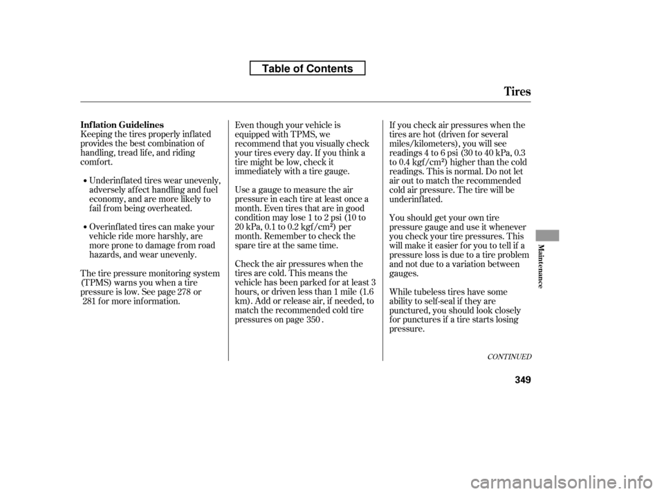
Keeping the tires properly inf lated
provides the best combination of
handling, tread lif e, and riding
comf ort.Underinf lated tires wear unevenly,
adversely affect handling and fuel
economy, and are more likely to
fail from being overheated.
Overinf lated tires can make your
vehicleridemoreharshly,are
more prone to damage f rom road
hazards, and wear unevenly. Even though your vehicle is
equipped with TPMS, we
recommend that you visually check
your tires every day. If you think a
tire might be low, check it
immediately with a tire gauge.
Use a gauge to measure the air
pressure in each tire at least once a
month. Even tires that are in good
condition may lose 1 to 2 psi (10 to
20 kPa, 0.1 to 0.2 kgf /cm ) per
month. Remember to check the
sparetireatthesametime.
Check the air pressures when the
tires are cold. This means the
vehicle has been parked f or at least 3
hours, or driven less than 1 mile (1.6
km). Add or release air, if needed, to
match the recommended cold tire
pressures on page . If you check air pressures when the
tires are hot (driven f or several
miles/kilometers), you will see
readings 4 to 6 psi (30 to 40 kPa, 0.3
to 0.4 kgf/cm ) higher than the cold
readings. This is normal. Do not let
air out to match the recommended
cold air pressure. The tire will be
underinf lated.
Youshouldgetyourowntire
pressure gauge and use it whenever
you check your tire pressures. This
will make it easier f or you to tell if a
pressure loss is due to a tire problem
and not due to a variation between
gauges.
While tubeless tires have some
ability to self -seal if they are
punctured, you should look closely
for punctures if a tire starts losing
pressure.
The tire pressure monitoring system
(TPMS) warns you when a tire
pressure is low. See page or
f or more inf ormation.
350
278
281
Tires
Inf lation Guidelines
Maint enance
349
Table of Contents
Page 40 of 421
Never use a puncture-repairing agent
in a f lat tire. If used, you will have to
replace the tire pressure sensor.
Havetheflattirerepairedbyyour
dealer as soon as possible.
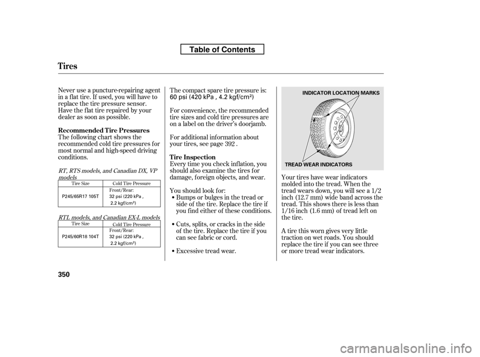
The following chart shows the
recommended cold tire pressures f or
most normal and high-speed driving
conditions.Your tires have wear indicators
molded into the tread. When the
tread wears down, you will see a 1/2
inch (12.7 mm) wide band across the
tread. This shows there is less than
1/16 inch (1.6 mm) of tread lef t on
the tire.
A tire this worn gives very little
traction on wet roads. You should
replace the tire if you can see three
or more tread wear indicators.
Thecompactsparetirepressureis:
Excessive tread wear.
Cuts, splits, or cracks in the side
of the tire. Replace the tire if you
can see f abric or cord.
Bumps or bulges in the tread or
side of the tire. Replace the tire if
youfindeitherof theseconditions.
Every time you check inf lation, you
should also examine the tires f or
damage, f oreign objects, and wear.
Youshouldlookfor:
For additional inf ormation about
your tires, see page .
For convenience, the recommended
tire sizes and cold tire pressures are
on a label on the driver’s doorjamb.
392
Tire Size Cold Tire Pressure
Cold Tire Pressure
Tire Size Front/Rear:
Front/Rear:
RT, RTS models, and Canadian DX, VP
models
RTL models, and Canadian EX-L models
Tires
Recommended Tire Pressures Tire Inspection
350
INDICATOR LOCATION MARKS
TREAD WEAR INDICATORS
32 psi (220 kPa , 2.2 kgf/cm
)
P245/65R17 105T
P245/60R18 104T 32 psi (220 kPa ,
2.2 kgf/cm
)
60 psi (420 kPa , 4.2 kgf/cm)
Table of Contents