coolant temperature Hyundai Coupe 2005 User Guide
[x] Cancel search | Manufacturer: HYUNDAI, Model Year: 2005, Model line: Coupe, Model: Hyundai Coupe 2005Pages: 478, PDF Size: 13.44 MB
Page 227 of 478
6
DO-IT-YOURSELF MAINTENANCE
29
G220B01A-AAT
Checking Engine Cooling Fan
The engine coolant fan should come on automatically if the engine coolant temperature is high. G220C01A-AAT
Checking Condenser Cooling Fan
The condenser coolant fan should come on automatically whenever the air conditioning is in operation. G230A03A-GAT
POWER STEERING FLUID LEVEL
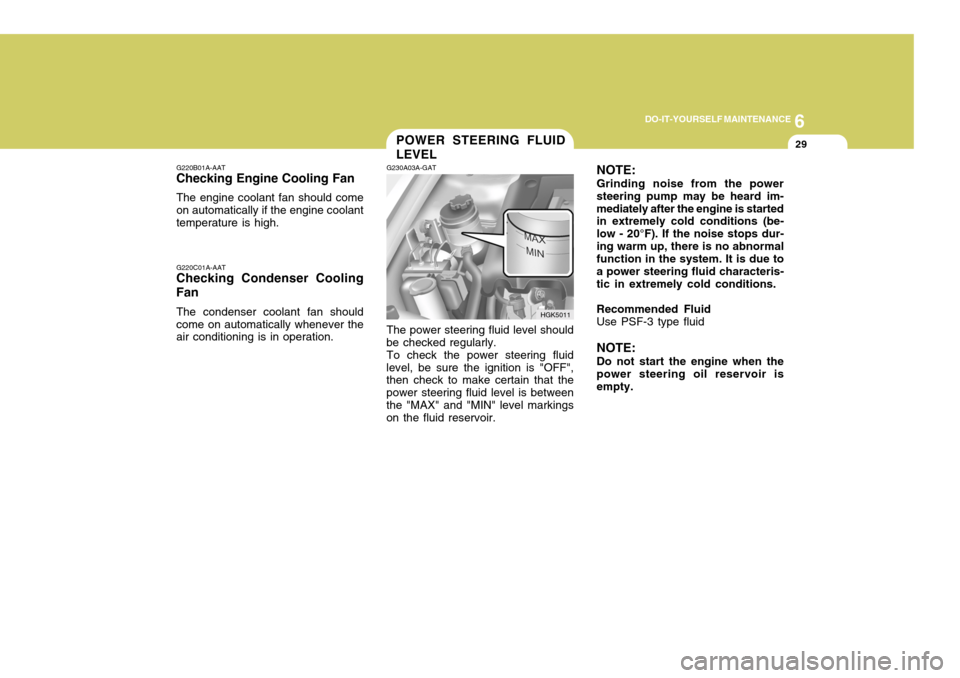
The power steering fluid level should
be checked regularly.
To check the power steering fluid
level, be sure the ignition is "OFF", then check to make certain that the power steering fluid level is betweenthe "MAX" and "MIN" level markings on the fluid reservoir. NOTE: Grinding noise from the power steering pump may be heard im-mediately after the engine is started in extremely cold conditions (be- low - 20°F). If the noise stops dur-ing warm up, there is no abnormal function in the system. It is due to a power steering fluid characteris-tic in extremely cold conditions. Recommended Fluid Use PSF-3 type fluid NOTE: Do not start the engine when the power steering oil reservoir isempty.
HGK5011
Page 243 of 478
7EMISSION CONTROL SYSTEMS
2
H010A01A-GAT (If Installed) Your Hyundai is equipped with an emission control system to meet all requirements of the Emission prohibi- tion rules of your province.There are three emission control sys-tems which are as follows.
(1) Crankcase emission control sys-
tem
(2) Evaporative emission control sys-
tem
(3) Exhaust emission control systemIn order to assure the proper function of the emission control systems, it isrecommended that you have your car inspected and maintained by an au- thorized Hyundai dealer in accordancewith the maintenance schedule in this manual. EMISSION CONTROL SYS- TEMS
H010B01F-GAT 1. Crankcase Emission Control
System
The positive crankcase ventilation system is employed to prevent air pollution caused by blow-by gases being emitted from the crankcase.This system supplies fresh air to the crankcase through the air cleaner. Inside the crankcase, the fresh airmixes with blow-by gases, then passes through the PCV valve into the induction system.
H010C01F-GAT
2. Evaporative Emission Control
System (If Installed)
The evaporative emission control sys-
tem is designed to prevent fuel va-pors from escaping into the atmo-sphere. H010D01A-AAT
3. Exhaust Emission Control
System
The exhaust emission control system is a highly effective system which controls exhaust emissions while maintaining good vehicle performace.
Canister While the engine is inoperative, fuel vapors generated inside the fuel tank are absorbed and stored in the canis-ter. When the engine is running, the fuel vapors absorbed in the canister are drawn into the induction systemthrough the purge control solenoid valve. Purge Control Solenoid Valve The purge control solenoid valve is controlled by the ECM; when the en- gine coolant temperature is low, and during idling, it closes, so that evapo- rated fuel is not taken into the engine. After engine warm-up, during ordi-nary driving, it opens so as to intro- duce evaporated fuel to the engine.
Page 257 of 478
10
INDEX
3
D Defrosting/Defogging ................................................... 1-82
Door
Central door lock ...................................................... 1-8
Door locks ................................................................ 1-7Locking and unlocking front door with a key ............ 1-7
Drink Holder ................................................................ 1-59
Drive Belts .................................................................. 6-24
Driving
Economical driving .................................................. 2-16
Smooth corneri ng ..................................................... 2-17
Winter driving ........................................................... 2-18
E
Emissions Control Systems ........................................ 7-2 Engine
Before starting the engine ........................................ 2-3
Changing the oil and filter ......................................... 6-8 Compartment (1.6L, 2.0L, 2.7L) ................................ 6-2
Coolant .................................................................... 6-10
Coolant temperature gauge ......................................1-46
If the engine overheats ............................................. 3-4
Number ..................................................................... 8-2
Oil ............................................................................. 6-6Oil consumption ........................................................ 6-7
Starting ..................................................................... 2-4
Engine Exhaust Can Be Dangerous ............................ 2-2 FFog Light
.................................................................... 1-56
Front Seats
Adjustable front seats .............................................. 1-13
Adjustable headrests ............................................... 1-14
Adjusting seat forward and rearward ........................1-13
Adjusting seatback angle .. ......................................1-14
Lumbar support control ............................................ 1-15
Seat cushion height adjustment .............................. 1-16
Seat warmer ............................................................ 1-16
Fuel
Capacity ................................................................... 9-2
Gauge ...................................................................... 1-46
Recommendations .................................................... 1-2
Fuel Filler Lid
Remote release ....................................................... 1-68
Fuse Panel Description .............................................. 6-40
Fuses ......................................................................... 6-25
G
General Everyday Checks ..... ...................................... 6-5
Glove box ................................................................... 1-64
Page 310 of 478
1
CONTROLS AND EQUIPMENT
39
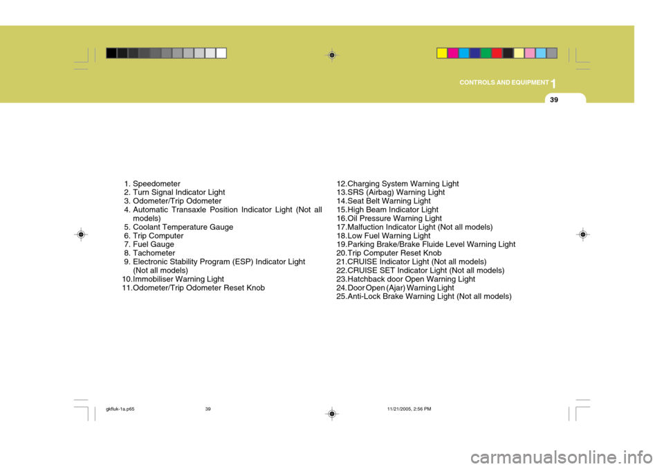
1. Speedometer
2. Turn Signal Indicator Light
3. Odometer/Trip Odometer
4. Automatic Transaxle Position Indicator Light (Not all models)
5. Coolant Temperature Gauge
6. Trip Computer
7. Fuel Gauge
8. Tachometer
9. Electronic Stability Program (ESP) Indicator Light (Not all models)
10.Immobiliser Warning Light
11.Odometer/Trip Odometer Reset Knob 12.Charging System Warning Light
13.SRS (Airbag) Warning Light
14.Seat Belt Warning Light
15.High Beam Indicator Light
16.Oil Pressure Warning Light
17.Malfuction Indicator Light (Not all models)
18.Low Fuel Warning Light
19.Parking Brake/Brake Fluide Level Warning Light
20.Trip Computer Reset Knob21.CRUISE Indicator Light (Not all models)
22.CRUISE SET Indicator Light (Not all models)
23.Hatchback door Open Warning Light
24. Door Open (Ajar) Warning Light
25.Anti-Lock Brake Warning Light (Not all models)
gkfluk-1a.p65
11/21/2005, 2:56 PM
39
Page 315 of 478
1CONTROLS AND EQUIPMENT
44
!
INSTRUMENT CLUSTER
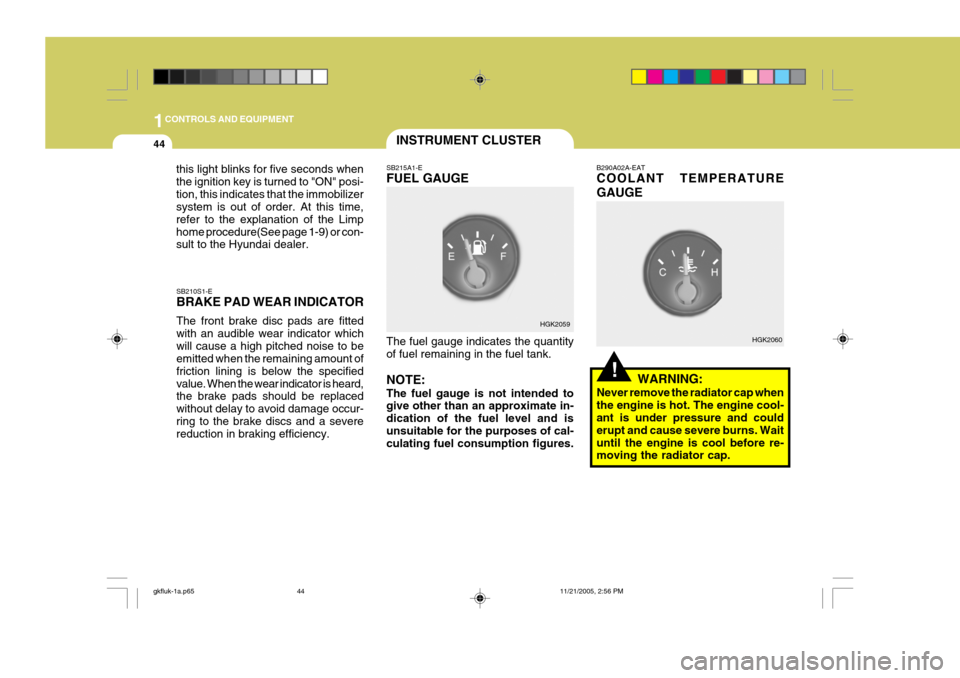
SB210S1-E BRAKE PAD WEAR INDICATOR The front brake disc pads are fitted with an audible wear indicator whichwill cause a high pitched noise to be emitted when the remaining amount of friction lining is below the specifiedvalue. When the wear indicator is heard, the brake pads should be replaced without delay to avoid damage occur-ring to the brake discs and a severe reduction in braking efficiency. SB215A1-E FUEL GAUGE The fuel gauge indicates the quantity of fuel remaining in the fuel tank. NOTE: The fuel gauge is not intended to give other than an approximate in- dication of the fuel level and isunsuitable for the purposes of cal- culating fuel consumption figures. B290A02A-EAT COOLANT TEMPERATURE GAUGE
WARNING:
Never remove the radiator cap when the engine is hot. The engine cool- ant is under pressure and could erupt and cause severe burns. Waituntil the engine is cool before re- moving the radiator cap.
HGK2059
HGK2060
this light blinks for five seconds when the ignition key is turned to "ON" posi-tion, this indicates that the immobilizer system is out of order. At this time, refer to the explanation of the Limphome procedure(See page 1-9) or con- sult to the Hyundai dealer.
gkfluk-1a.p65
11/21/2005, 2:56 PM
44
Page 387 of 478
2DRIVING YOUR HYUNDAI
20
C190E01L
CAUTION:
o Never connect a trailer brake sys- tem directly to the vehicle brake system.
o When towing a trailer on steep grades (in excess of 12%) payclose attention to the engine cool-ant temperature gauge to ensure the engine does not overheat. If the needle of the coolant tem-perature gauge moves across the dial towards "H" (HOT), pull over and stop as soon as it is safe todo so, and allow the engine to idle until it cools down. You may proceed once the engine hascooled sufficiently.
! YC200D2-E Safety Cables Should the towbar connection between your car and the trailer or vehicle youare towing fail, the trailer or vehicle could wander dangerously across other lanes of traffic and ultimately leave theroadway. To eliminate this potentially dangerous situation, safety cable, at- tached between your car and the traileror towed vehicle, are required.
Nose weight Total trailer weight
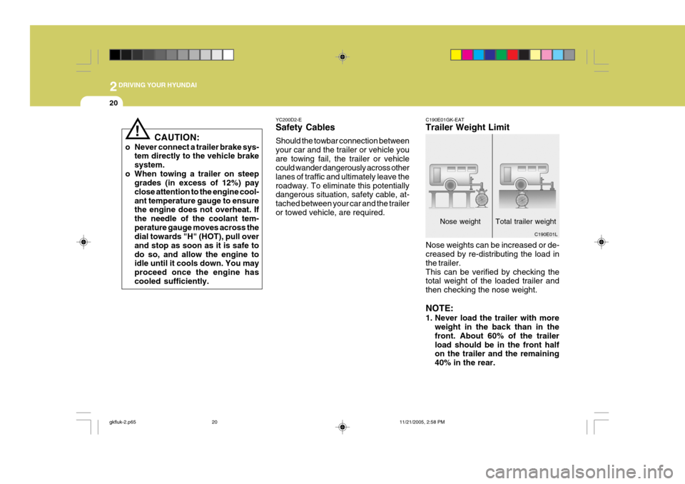
C190E01GK-EAT Trailer Weight Limit Nose weights can be increased or de- creased by re-distributing the load in the trailer.This can be verified by checking the total weight of the loaded trailer and then checking the nose weight. NOTE:
1. Never load the trailer with more
weight in the back than in the front. About 60% of the trailerload should be in the front half on the trailer and the remaining 40% in the rear.
gkfluk-2.p65 11/21/2005, 2:58 PM
20
Page 394 of 478
3 IN CASE OF EMERGENCY
4
7. Swithc "ON" the main beam
headlamps before carefully remov- ing the jumper cables have been removed, switch "OFF" the main beam geadlamps. SD040A2-E If the temperature gauge indicates overheating:
1. Pull off the road and stop as soon as
it is safe to do so.
2. Place the gear selector lever in "P"
(automatic), or neutral (manual transaxle) and set the parking brake. If the air conditioning is on, turn it off.
3. If coolant is running out under the car or steam is coming out fromunder the bonnet stop the engine. Do not open the bonnet until thecoolant has stopped running or the steaming has stopped. If there is no visible loss of coolant and no steam,leave the engine running and check to be sure the engine cooling fan is operating.If the fan is not running, turn the engine off.
4. Check to see if the water pump drive belt is broken. If it is not missing,check to see that it is tight. If the drive belt seems to be satisfac-tory,check for coolant leaking from the radiator, hoses or under the car. (If the air conditioning had been in use,it is normal for cold water to be draining from it).
IF THE ENGINE OVERHEATS
1. Ensure that the booster battery is 12 volt type. If the booster battery is installed in another vehicle, ensure that the two vehicles are not touch- ing.
2. Turn off all unnecessary electrical equipment in both vehicles.
3. Ensure that the engine of the ve- hicle providing the jump start is run- ning prior to connection of the jump cables.
4. Connect the red jump cable to the positive (+) terminal of the boosterbattery and the other end to thepositive (+) terminal of the dis- charged battery.
5. Attach the black jump cable to the negative (-) terminal of thebooster battery, and the other end to a ground point within the enginecompartment of the vehicle with the flat battery. Do not connect to the negative battery terminal of the flatbattery since sparks may be gener- ated with the subsequent risk of explosion.
6. Raise the booster vehicle engine speed to 2,000 r.p.m. and start theengine of the vehicle with the flatbattery. CAUTION:
If the jump cables are incorrectlyinstalled, damage to the vehicle elec-trical system may occur, in particu- lar the electronic components such as the Fuel Injection system com- puter and the Automatic Transaxle computer. The battery must neverbe disconnected whilst the engine is running.
!
gkfluk-3.p65 11/21/2005, 3:02 PM
4
Page 395 of 478
3
IN CASE OF EMERGENCY
5
!
!WARNING:
Whilst the engine is running, keep hands and clothing away from mov- ing parts such as the fan and drive belts to prevent injury.
5. If the water pump drive belt is broken or coolant is leaking out, stop the engine immediately and call the near- est Hyundai authorised repairer forassistance.
WARNING:
Do not remove the radiator cap when the engine is hot since steam and boiling water may be ejected fromthe radiator resulting in burns or scalding.
!
6. If the cause of the overheating can- not be found, wait until the engine temperature has returned to normal. Then, if coolant has been lost, care- fully add coolant to the reservoir(page 6-11) to bring the fluid level in the reservoir up to the base of the radiator fill opening. Fill the coolantexpansion tank to the halfway mark. To ensure the correct water to cool- ant mix is obtained after top up,testing by an authorised repairer is required.
7. Proceed with caution until it is estab- lished that the engine is operatingnormally. If the engine overheats repeatedly, the advice of a Hyundaiauthorised repairer should be sought.
CAUTION:
Serious loss of coolant indicates there is a leak in the cooling system and this should be checked as soonas possible by a Hyundai authorised repairer.D040A01GK-EAT TEMPORARY SPARE TYRE The following instructions for the tem- porary spare tyre should be observed:
1. Check inflation pressure as soon as practical after installing the spare tyre, and adjust to the specified pressure. The tyre pressure should be periodically checked and main-tained at the specified pressure while the tyre is stored.
2. The spare tyre should only be used temporarily and should be returnedto the luggage compartment as soon as the original tyre can be repairedor replaced.
SPARE TYRE
Tyre Size
Inflation Pressure T125/70 R16
420 kPa (60 psi)
Spare Tyre Pressure
3. Continuous use at speeds of over 50 mph (80 km/h) is not recom- mended.
4. As the temporary spare tyre is spe-
cifically designed for your car, itshould not be used on any other vehicle.
gkfluk-3.p65 11/21/2005, 3:02 PM
5
Page 429 of 478
6
OWNER MAINTENANCE
11
HGK4006
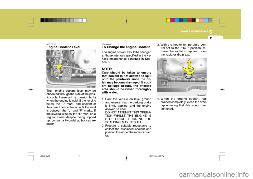
SG050C1-E
Engine Coolant Level
The engine coolant level may be
observed through the side of the plas- tic coolant reservoir (expansion tank) when the engine is cold. If the level is below the "L" mark, add coolant ofthe correct concentration until the level is between the "L" and "F" marks. If the level falls below the "L" mark on aregular basis despite being topped up, consult a Hyundai authorised re- pairer. SG050D1-E
To Change the engine Coolant
The engine coolant should be changedat those intervals specified in the ve- hicle maintenance schedule in Sec- tion 5. NOTE: Care should be taken to ensure that coolant is not allowed to spill onto the paintwork since the fin- ish may become damaged. If cool-ant spillage occurs, the affected area should be rinsed thoroughly with water.
1. Park the vehicle on level ground and ensure that the parking brake is firmly applied, and the engine allowed to cool.DO NOT ATTEMPT THIS OPERA-TION WHILST THE ENGINE ISHOT SINCE BURNING OR SCALDING MAY RESULT.
2. Prepare a suitable receptacle to collect the displaced coolant andposition this under the radiator drain tap. 4. When the engine coolant has
drained completely, close the drain tap ensuring that this is not over tightened. G050D03E
3. With the heater temperature con-
trol set to the "HOT" position, re-move the radiator cap and open the radiator drain tap.
gkfluk-6.p65 11/21/2005, 3:00 PM
11
Page 430 of 478

6OWNER MAINTENANCE
12CHANGING THE AIR CLEANER FILTER
G070A01E-AAT To change the filter, unsnap the clips
around the cover. When this is done, the cover can be lifted off, the oldfilter removed and the new filter put in its place. Genuine Hyundai Replace- ment Parts are recommended.
HGK5010
! CAUTION:
o Operating your vehicle without a proper air cleaner filter in place can result in excessive engine wear.
o When removing the air cleaner filter, be careful that dust or dirtdoes not enter the air intake. These may result in damage tothe air cleaner filter.
G050D04E
!WARNING:
The cooling fan is controlled by engine coolant temperature and may sometimes operate even whenthe engine is not running. Use extreme caution when working near the blades of the cooling fan sothat you are not injured by a rotat- ing fan blade. As the engine cool- ant temperature decreases, the fanwill automatically shut off. This is a normal condition.
5. Prepare a suitable quantity of new
engine coolant (refer to section 9) and pour this into the radiator.
6. Start the engine with the radiator cap still removed and continue to add coolant as the level decreases as air is expelled from the system.When the level remains constant, replace the radiator cap and re- plenish the coolant reservoir.
7. When the engine is hot, check to ensure that no coolant leaks arepresent.
gkfluk-6.p65 11/21/2005, 3:00 PM
12