Instrument cluster Hyundai Elantra 2010 Owner's Manual
[x] Cancel search | Manufacturer: HYUNDAI, Model Year: 2010, Model line: Elantra, Model: Hyundai Elantra 2010Pages: 348, PDF Size: 5.78 MB
Page 8 of 348
1
How to use this manual / 1-2
Fuel requirements / 1-3
Vehicle break-in process / 1-5
Vehicle data collection and event data recorders / 1-6
Indicator symbols on the instrument cluster / 1-7
Introduction
Page 14 of 348
17
Introduction
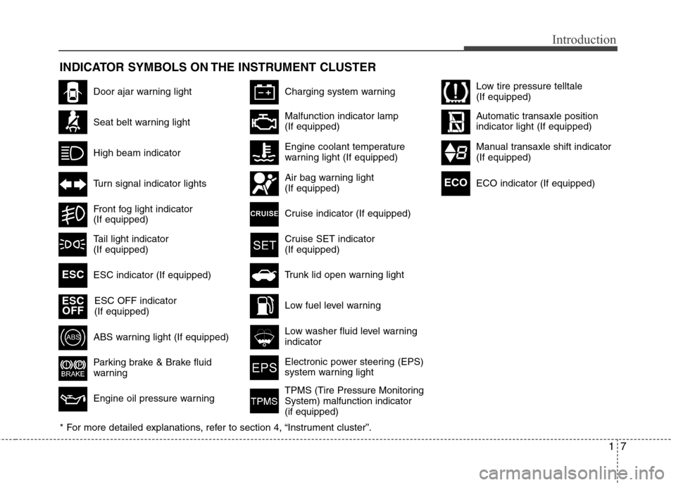
INDICATOR SYMBOLS ON THE INSTRUMENT CLUSTER
Door ajar warning light
Seat belt warning light
High beam indicator
Turn signal indicator lights
Front fog light indicator
(If equipped)
ABS warning light (If equipped)
Parking brake & Brake fluid
warning
Engine oil pressure warning
Charging system warning
ESC indicator (If equipped) ESC OFF indicator
(If equipped)
Malfunction indicator lamp
(If equipped)
Engine coolant temperature
warning light (If equipped)
Air bag warning light
(If equipped)
Cruise indicator (If equipped)
Cruise SET indicator
(If equipped)
Low fuel level warning
Low washer fluid level warning
indicator
Electronic power steering (EPS)
system warning light
Trunk lid open warning light
* For more detailed explanations, refer to section 4, “Instrument cluster”.ESC
ESC OFF
TPMS (Tire Pressure Monitoring
System) malfunction indicator
(if equipped)
Low tire pressure telltale
(If equipped)
Automatic transaxle position
indicator light (If equipped)
Manual transaxle shift indicator
(If equipped)
Tail light indicator
(If equipped) ECO indicator (If equipped)
ECO
Page 17 of 348
23
Your vehicle at a glance
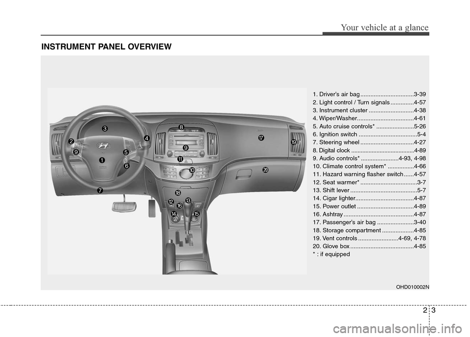
INSTRUMENT PANEL OVERVIEW
1. Driver’s air bag ................................3-39
2. Light control / Turn signals ..............4-57
3. Instrument cluster ...........................4-38
4. Wiper/Washer..................................4-61
5. Auto cruise controls * .......................5-26
6. Ignition switch ...................................5-4
7. Steering wheel ................................4-27
8. Digital clock ........................................4-89
9. Audio controls * .......................4-93, 4-98
10. Climate control system * ................4-66
11. Hazard warning flasher switch ......4-57
12. Seat warmer* ..................................3-7
13. Shift lever ........................................5-7
14. Cigar lighter...................................4-87
15. Power outlet ..................................4-89
16. Ashtray ..........................................4-87
17. Passenger’s air bag ......................3-40
18. Storage compartment ...................4-85
19. Vent controls ........................4-69, 4-78
20. Glove box ......................................4-85
* : if equipped
OHD010002N
Page 49 of 348
Safety features of your vehicle
32
3
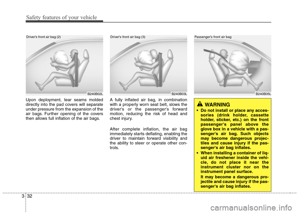
B240B05L
Passenger’s front air bag
Upon deployment, tear seams molded
directly into the pad covers will separate
under pressure from the expansion of the
air bags. Further opening of the covers
then allows full inflation of the air bags. A fully inflated air bag, in combination
with a properly worn seat belt, slows the
driver's or the passenger's forward
motion, reducing the risk of head and
chest injury.
After complete inflation, the air bag
immediately starts deflating, enabling the
driver to maintain forward visibility and
the ability to steer or operate other con-
trols.
B240B02L
B240B03L
Driver’s front air bag (2)Driver’s front air bag (3)
WARNING
Do not install or place any acces-
sories (drink holder, cassette
holder, sticker, etc.) on the front
passenger's panel above the
glove box in a vehicle with a pas-
senger's air bag. Such objects
may become dangerous projec-
tiles and cause injury if the pas-
senger's air bag inflates.
When installing a container of liq- uid air freshener inside the vehi-
cle, do not place it near the
instrument cluster nor on the
instrument panel surface.
It may become a dangerous pro-
jectile and cause injury if the pas-
senger's air bag inflates.
Page 74 of 348
4
Keys / 4-2
Remote keyless entry / 4-3
Theft-alarm system / 4-6
Door locks / 4-8
Trunk / 4-12
Windows / 4-14
Hood / 4-18
Fuel filler lid / 4-20
Sunroof / 4-23
Steering wheel / 4-27
Mirrors / 4-29
Instrument cluster / 4-38
Hazard warning flasher / 4-57
Lighting / 4-57
Wipers and washers / 4-61
Interior light / 4-62
Defroster / 4-65
Manual climate control system / 4-66
Automatic climate control system / 4-75
Windshield defrosting and defogging / 4-82
Storage compartment / 4-85
Interior features / 4-87
Audio system / 4-92
Features of your vehicle
Page 111 of 348
Features of your vehicle
38
4
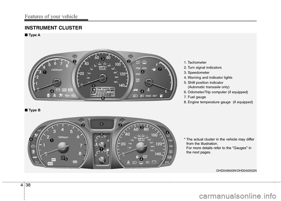
INSTRUMENT CLUSTER
1. Tachometer
2. Turn signal indicators
3. Speedometer
4. Warning and indicator lights
5. Shift position indicator
(Automatic transaxle only)
6. Odometer/Trip computer (if equipped)
7. Fuel gauge
8. Engine temperature gauge (if equipped)
OHD049500N/OHD040552N
■
■ Type A
■
■ Type B
* The actual cluster in the vehicle may differfrom the illustration.
For more details refer to the "Gauges" in
the next pages.
Page 115 of 348
Features of your vehicle
42
4
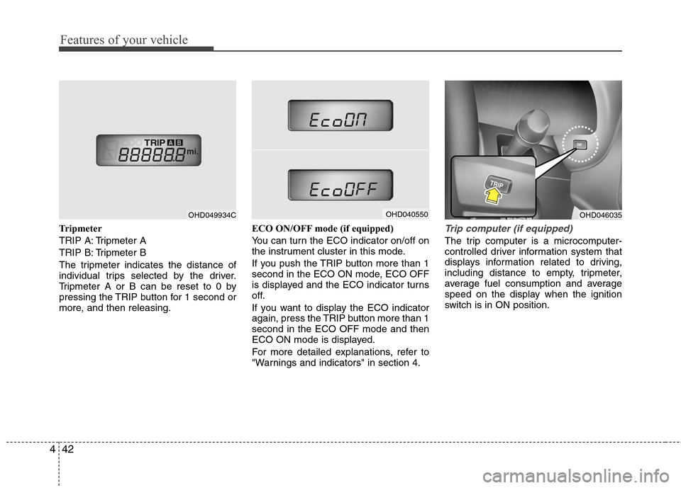
Tripmeter
TRIP A: Tripmeter A
TRIP B: Tripmeter B
The tripmeter indicates the distance of
individual trips selected by the driver.
Tripmeter A or B can be reset to 0 by
pressing the TRIP button for 1 second or
more, and then releasing. ECO ON/OFF mode (if equipped)
You can turn the ECO indicator on/off on
the instrument cluster in this mode.
If you push the TRIP button more than 1
second in the ECO ON mode, ECO OFF
is displayed and the ECO indicator turns
off.
If you want to display the ECO indicator
again, press the TRIP button more than 1
second in the ECO OFF mode and then
ECO ON mode is displayed.
For more detailed explanations, refer to
"Warnings and indicators" in section 4.Trip computer (if equipped)
The trip computer is a microcomputer-
controlled driver information system that
displays information related to driving,
including distance to empty, tripmeter,
average fuel consumption and average
speed on the display when the ignition
switch is in ON position.
OHD049934C
OHD046035
OHD040550
Page 119 of 348
Features of your vehicle
46
4
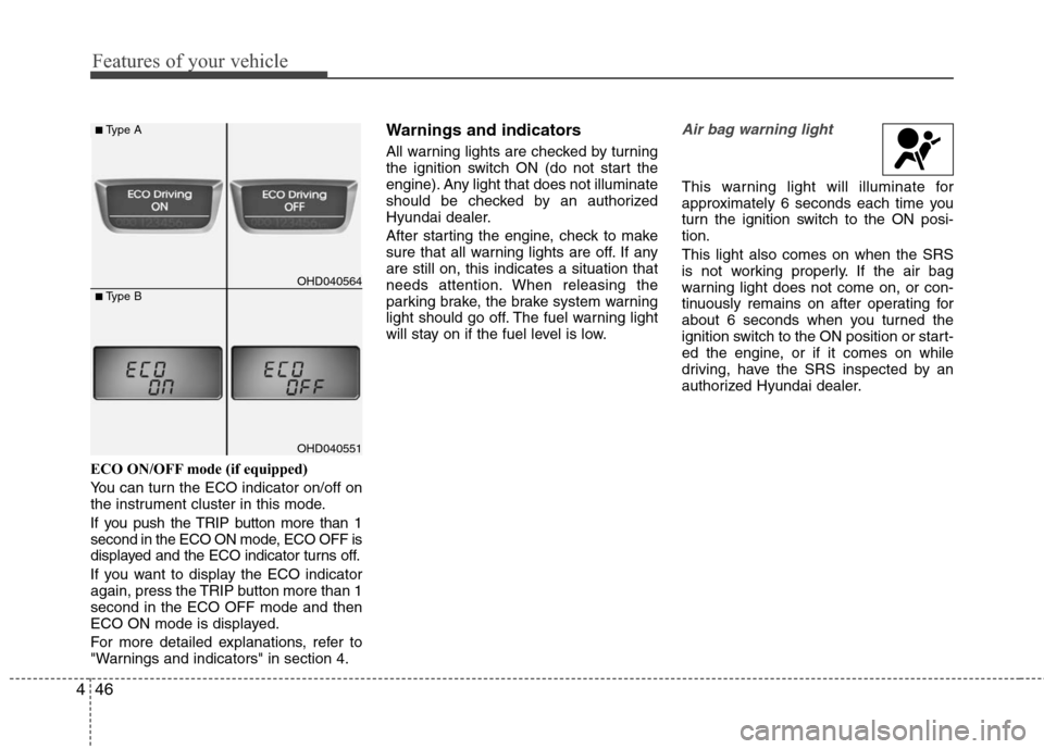
ECO ON/OFF mode (if equipped)
You can turn the ECO indicator on/off on
the instrument cluster in this mode.
If you push the TRIP button more than 1
second in the ECO ON mode, ECO OFF is
displayed and the ECO indicator turns off.
If you want to display the ECO indicator
again, press the TRIP button more than 1
second in the ECO OFF mode and then
ECO ON mode is displayed.
For more detailed explanations, refer to
"Warnings and indicators" in section 4.
Warnings and indicators
All warning lights are checked by turning
the ignition switch ON (do not start the
engine). Any light that does not illuminate
should be checked by an authorized
Hyundai dealer.
After starting the engine, check to make
sure that all warning lights are off. If any
are still on, this indicates a situation that
needs attention. When releasing the
parking brake, the brake system warning
light should go off. The fuel warning light
will stay on if the fuel level is low.
Air bag warning light
This warning light will illuminate for
approximately 6 seconds each time you
turn the ignition switch to the ON posi-
tion.
This light also comes on when the SRS
is not working properly. If the air bag
warning light does not come on, or con-
tinuously remains on after operating for
about 6 seconds when you turned the
ignition switch to the ON position or start-
ed the engine, or if it comes on while
driving, have the SRS inspected by an
authorized Hyundai dealer.
OHD040564
■Type A
■Type B
OHD040551
Page 125 of 348
Features of your vehicle
52
4
ESC (Electronic Stability
Control) indicator(if equipped)
The ESC indicator will illuminate when
the ignition switch is turned ON, but
should go off after approximately 3 sec-
onds. When the ESC is on, it monitors
the driving conditions and under normal
driving conditions, the ESC light will
remain off. When a slippery or low trac-
tion condition is encountered, the ESC
will operate, and the ESC indicator will
blink to indicate the ESC is operating.
ESC OFF indicator (if equipped)
The ESC OFF indicator will illuminate
when the ignition switch is turned ON,
but should go off after approximately 3
seconds. To switch to ESC OFF mode,
press the ESC OFF button. The ESC
OFF indicator will illuminate indicating
the ESC is deactivated. If this indicator
stays on in the ESC ON mode, the ESC
may have a malfunction. Take your car to
an authorized Hyundai dealer and have
the system checked.
Cruise indicator (if equipped)
CRUISE indicator
The indicator light illuminates when the
cruise control system is enabled.
The cruise indicator light in the instru-
ment cluster is illuminated when the
cruise control ON/OFF button on the
steering wheel is pulled.
The indicator light turns off when the
cruise control ON/OFF button is pushed
again. For more Information about the
use of cruise control, refer to section 5,
“Cruise control system”.
Cruise SET indicator
The indicator light illuminates when the
cruise function switch (COAST/SET or
RES/ACCEL) is ON.
The cruise SET indicator light in the
instrument cluster is illuminated when
the cruise control switch (COAST/SET or
RES/ACCEL) is pushed. The cruise SET
indicator light does not illuminate when
the cruise control switch (CANCEL) is
pushed or the system is disengaged.
Key reminder warning chime
(if equipped)
If the driver’s door is opened while the
ignition key is left in the ignition switch
(ACC or LOCK position), the key
reminder warning chime will sound. This
is to prevent you from locking your keys
in the vehicle. The chime sounds until the
key is removed from the ignition switch or
the driver’s door is closed.
Electronic power steering (EPS) system warning light
This indicator light comes on after the
ignition key is turned to the ON position
and then it will go out with the engine
started.
This light also comes on if the EPS has a
malfunction. If it comes on while driving,
have your vehicle inspected by an
authorized Hyundai dealer.
ESC
CRUISE
ESCOFF
SET
EPS
Page 204 of 348
Driving your vehicle
12
5
Transaxle ranges
The indicator lights in the instrument
cluster indicate the shift lever position
when the ignition switch is in the ON
position.
P (Park)
Always come to a complete stop before
shifting into P (Park). This position locks
the transaxle and prevents the front
wheels from rotating. R (Reverse)
Use this position to drive the vehicle
backward.
N (Neutral)
The wheels and transaxle are not locked.
The vehicle will roll freely even on the
slightest incline unless the parking brake
or service brakes are applied.
D (Drive)
This is the normal forward driving posi-
tion. The transaxle will automatically shift
through a 4-gear sequence, providing the
best fuel economy and power.
For extra power when passing another
vehicle or climbing grades, depress the
accelerator fully, at which time the
transaxle will automatically downshift to
the next lower gear.(Continued)
Before leaving the driver’s seat,
always make sure the shift lever
is in the P (Park) position. Set the
parking brake fully, shut the
engine off and take the key with
you. Unexpected and sudden
vehicle movement can occur if
you do not follow these precau-
tions in the order specified.
Never leave a child unattended in a vehicle.
WARNING
Shifting into P (Park) while thevehicle is in motion will cause the
drive wheels to lock which will
cause you to lose control of the
vehicle.
Do not use the P (Park) position in place of the parking brake.
Always make sure the shift lever
is latched in the P (Park) position
and set the parking brake fully.
(Continued)
CAUTION
The transaxle may be damaged ifyou shift into P (Park) while thevehicle is in motion.
CAUTION
Always come to a complete stopbefore shifting into or out of R(Reverse); you may damage thetransaxle if you shift into R whilethe vehicle is in motion, except asexplained in “Rocking the Vehicle”,in this manual.