HYUNDAI ELANTRA SPORT 2019 Owners Manual
Manufacturer: HYUNDAI, Model Year: 2019, Model line: ELANTRA SPORT, Model: HYUNDAI ELANTRA SPORT 2019Pages: 534, PDF Size: 51.51 MB
Page 481 of 534
7-56
Maintenance
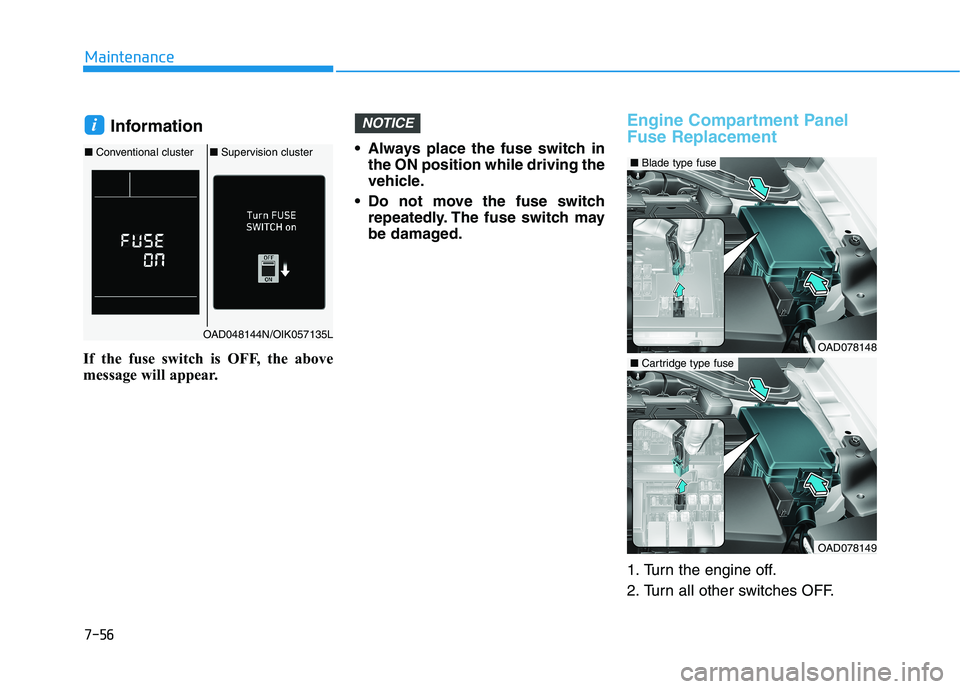
Information
If the fuse switch is OFF, the above
message will appear. Always place the fuse switch in
the ON position while driving the
vehicle.
Do not move the fuse switch repeatedly. The fuse switch may
be damaged.Engine Compartment Panel Fuse Replacement
1. Turn the engine off.
2. Turn all other switches OFF.
NOTICEi
OAD078148
OAD078149
■Blade type fuse
■Cartridge type fuse
OAD048144N/OIK057135L
■Conventional cluster ■Supervision cluster
Page 482 of 534
7-57
Maintenance
3. Remove the fuse panel cover bypressing the tap and pulling up.
4. Check the removed fuse; replace it if it is blown. To remove or insert
the fuse, use the fuse puller in the
engine compartment fuse panel.
5. Push in a new fuse of the same rating, and make sure it fits tightly
in the clips. If it fits loosely, consult
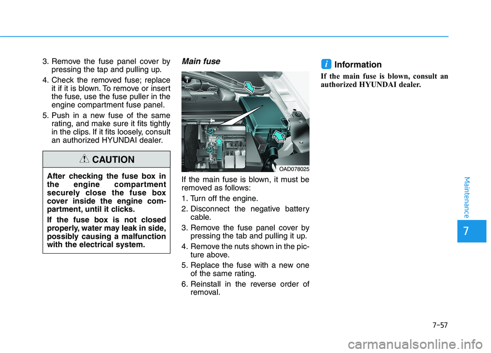
an authorized HYUNDAI dealer.Main fuse
If the main fuse is blown, it must be
removed as follows:
1. Turn off the engine.
2. Disconnect the negative batterycable.
3. Remove the fuse panel cover by pressing the tab and pulling it up.
4. Remove the nuts shown in the pic- ture above.
5. Replace the fuse with a new one of the same rating.
6. Reinstall in the reverse order of removal. Information
If the main fuse is blown, consult an
authorized HYUNDAI dealer.
i
After checking the fuse box in
the engine compartment
securely close the fuse box
cover inside the engine com-
partment, until it clicks.
If the fuse box is not closed
properly, water may leak in side,
possibly causing a malfunctionwith the electrical system.
CAUTION
OAD078025
7
Page 483 of 534
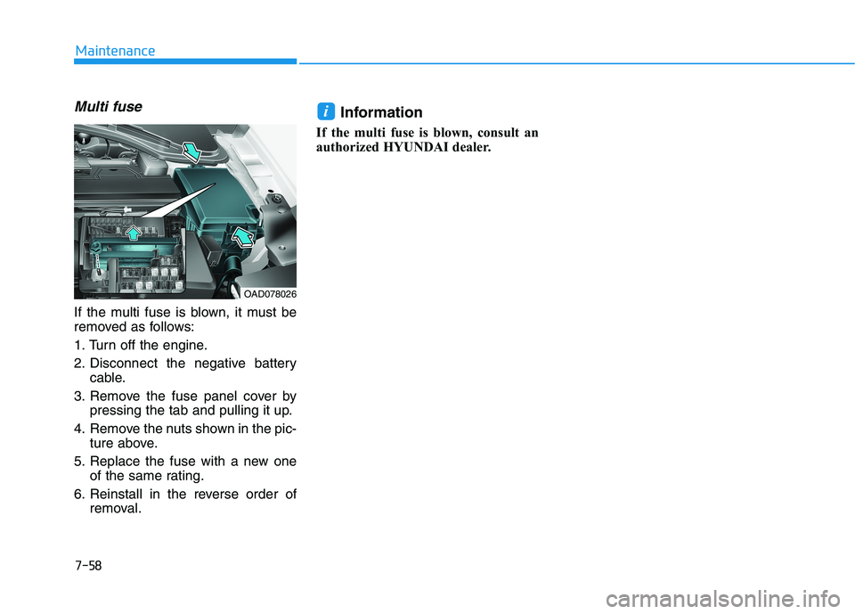
Multi fuse
If the multi fuse is blown, it must be
removed as follows:
1. Turn off the engine.
2. Disconnect the negative batterycable.
3. Remove the fuse panel cover by pressing the tab and pulling it up.
4. Remove the nuts shown in the pic- ture above.
5. Replace the fuse with a new one of the same rating.
6. Reinstall in the reverse order of removal. Information
If the multi fuse is blown, consult an
authorized HYUNDAI dealer.
i
7-58
Maintenance
OAD078026
Page 484 of 534
7-59
7
Maintenance
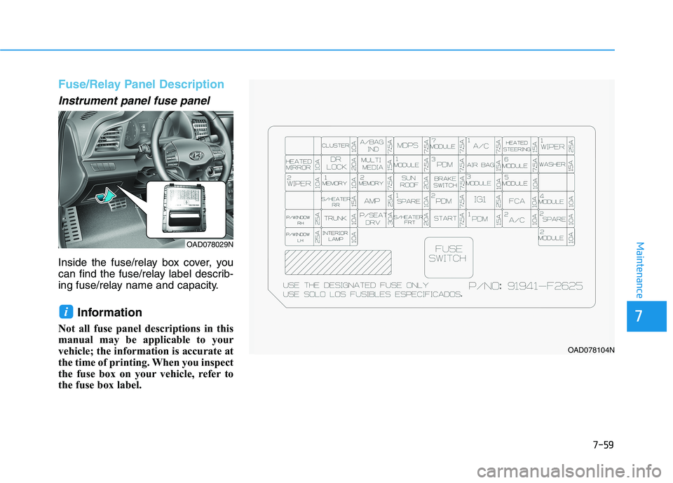
Fuse/Relay Panel Description
Instrument panel fuse panel
Inside the fuse/relay box cover, you
can find the fuse/relay label describ-
ing fuse/relay name and capacity.Information
Not all fuse panel descriptions in this
manual may be applicable to your
vehicle; the information is accurate at
the time of printing. When you inspect
the fuse box on your vehicle, refer to
the fuse box label.
i
OAD078029N
OAD078104N
Page 485 of 534
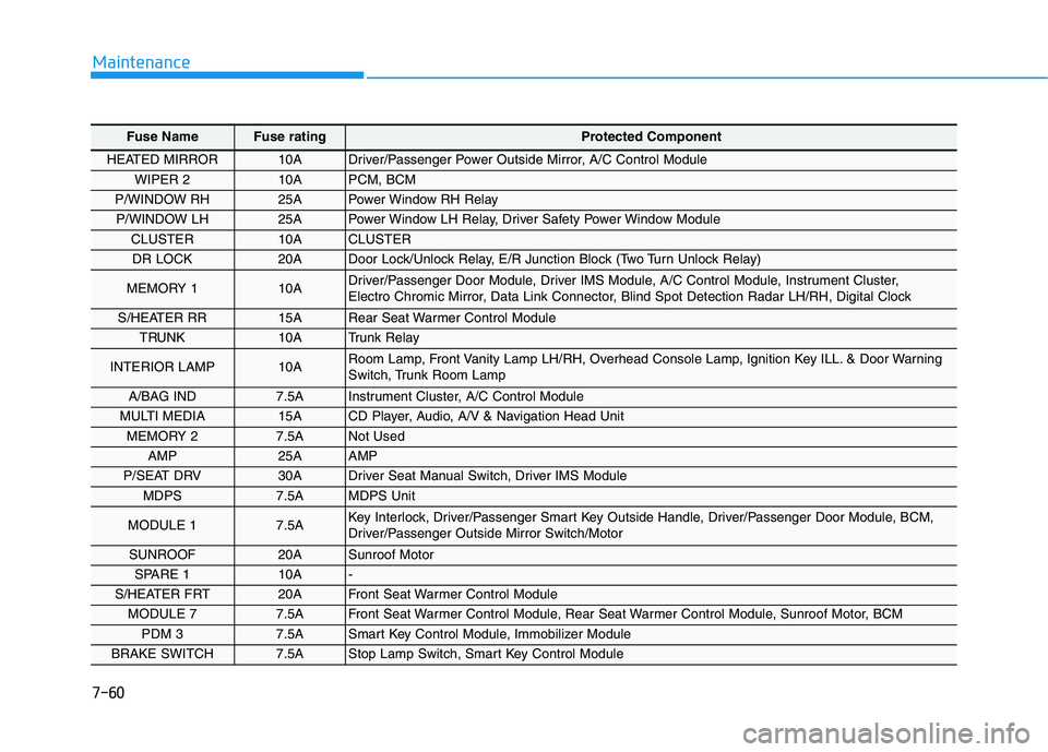
7-60
Maintenance
Fuse Name Fuse rating Protected Component
HEATED MIRROR 10A Driver/Passenger Power Outside Mirror, A/C Control Module
WIPER 2 10A PCM, BCM
P/WINDOW RH 25A Power Window RH Relay
P/WINDOW LH 25A Power Window LH Relay, Driver Safety Power Window Module
CLUSTER 10A CLUSTER
DR LOCK 20A Door Lock/Unlock Relay, E/R Junction Block (Two Turn Unlock Relay)
MEMORY 1 10A Driver/Passenger Door Module, Driver IMS Module, A/C Control Module, Instrument Cluster,
Electro Chromic Mirror, Data Link Connector, Blind Spot Detection Radar LH/RH, Digital Clock
S/HEATER RR 15A Rear Seat Warmer Control Module
TRUNK 10A Trunk Relay
INTERIOR LAMP 10A Room Lamp, Front Vanity Lamp LH/RH, Overhead Console Lamp, Ignition Key ILL. & Door Warning
Switch, Trunk Room Lamp
A/BAG IND 7.5A Instrument Cluster, A/C Control Module
MULTI MEDIA 15A CD Player, Audio, A/V & Navigation Head Unit
MEMORY 2 7.5A Not Used
AMP 25A AMP
P/SEAT DRV 30A Driver Seat Manual Switch, Driver IMS Module
MDPS 7.5A MDPS Unit
MODULE 1 7.5A Key Interlock, Driver/Passenger Smart Key Outside Handle, Driver/Passenger Door Module, BCM,
Driver/Passenger Outside Mirror Switch/Motor
SUNROOF 20A Sunroof Motor
SPARE 1 10A -
S/HEATER FRT 20A Front Seat Warmer Control Module
MODULE 7 7.5A Front Seat Warmer Control Module, Rear Seat Warmer Control Module, Sunroof Motor, BCM
PDM 3 7.5A Smart Key Control Module, Immobilizer Module
BRAKE SWITCH 7.5A Stop Lamp Switch, Smart Key Control Module
Page 486 of 534
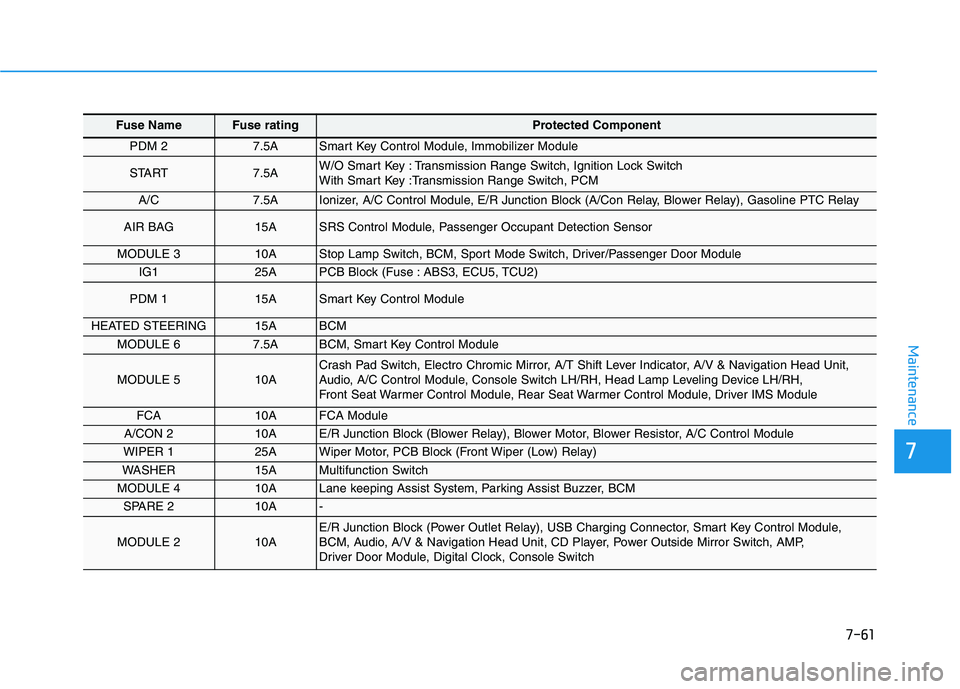
7-61
Maintenance
Fuse Name Fuse rating Protected Component
PDM 2 7.5A Smart Key Control Module, Immobilizer Module
START 7.5A W/O Smart Key : Transmission Range Switch, Ignition Lock Switch
With Smart Key :Transmission Range Switch, PCM
A/C7.5A Ionizer, A/C Control Module, E/R Junction Block (A/Con Relay, Blower Relay), Gasoline PTC Relay
AIR BAG 15A SRS Control Module, Passenger Occupant Detection Sensor
MODULE 3 10A Stop Lamp Switch, BCM, Sport Mode Switch, Driver/Passenger Door Module
IG1 25A PCB Block (Fuse : ABS3, ECU5, TCU2)
PDM 1 15A Smart Key Control Module
HEATED STEERING 15A BCM
MODULE 6 7.5A BCM, Smart Key Control Module
MODULE 5 10A Crash Pad Switch, Electro Chromic Mirror, A/T Shift Lever Indicator, A/V & Navigation Head Unit,
Audio, A/C Control Module, Console Switch LH/RH, Head Lamp Leveling Device LH/RH,
Front Seat Warmer Control Module, Rear Seat Warmer Control Module, Driver IMS Module
FCA10A FCA Module
A/CON 2 10A E/R Junction Block (Blower Relay), Blower Motor, Blower Resistor, A/C Control Module
WIPER 1 25A Wiper Motor, PCB Block (Front Wiper (Low) Relay)
WASHER 15A Multifunction Switch
MODULE 4 10A Lane keeping Assist System, Parking Assist Buzzer, BCM
SPARE 2 10A -
MODULE 2 10A E/R Junction Block (Power Outlet Relay), USB Charging Connector, Smart Key Control Module,
BCM, Audio, A/V & Navigation Head Unit, CD Player, Power Outside Mirror Switch, AMP,
Driver Door Module, Digital Clock, Console Switch
7
Page 487 of 534
7-62
Maintenance
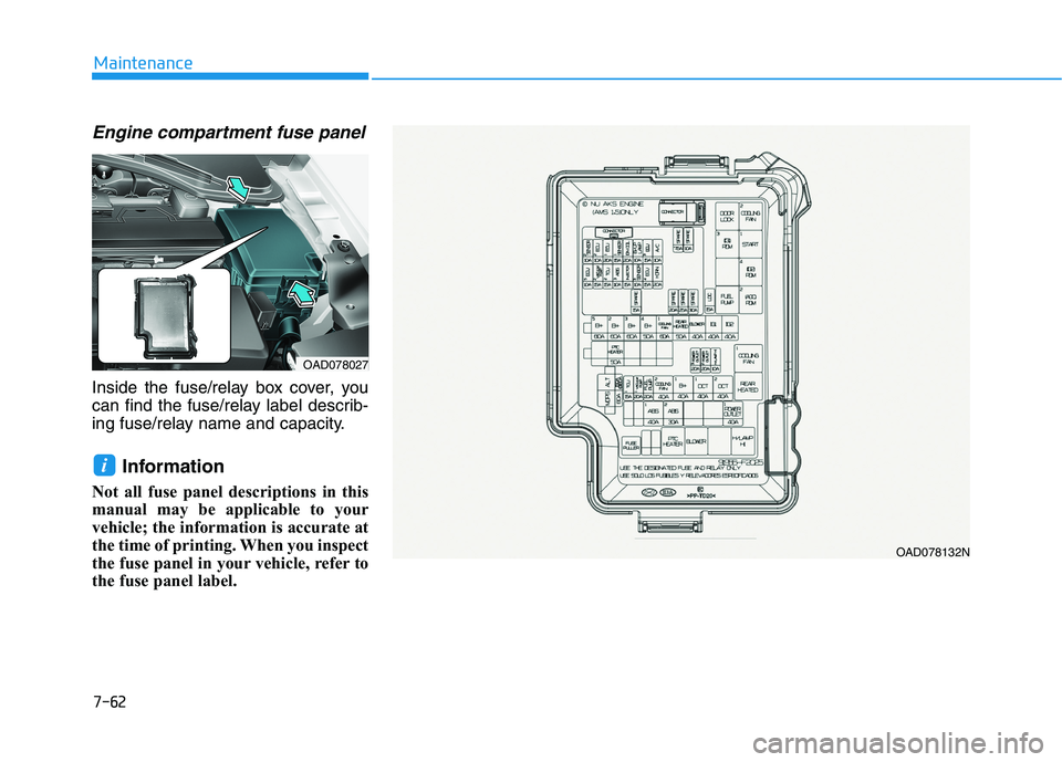
Engine compartment fuse panel
Inside the fuse/relay box cover, you
can find the fuse/relay label describ-
ing fuse/relay name and capacity.Information
Not all fuse panel descriptions in this
manual may be applicable to your
vehicle; the information is accurate at
the time of printing. When you inspect
the fuse panel in your vehicle, refer to
the fuse panel label.
i
OAD078027
OAD078132N
Page 488 of 534
7-63
7
Maintenance
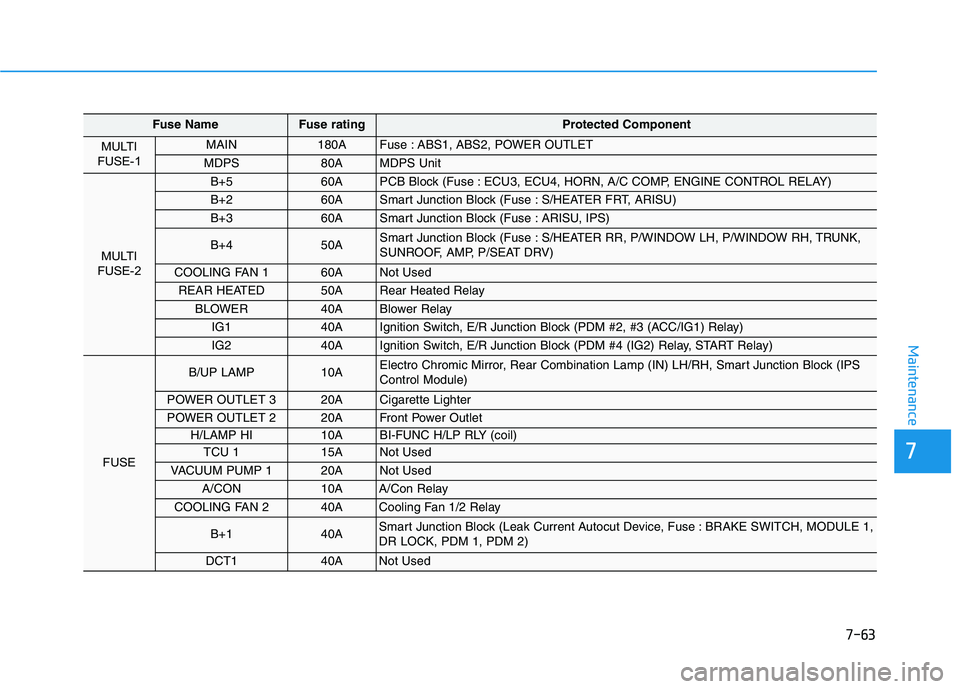
Fuse NameFuse rating Protected Component
MULTI
FUSE-1 MAIN 180A Fuse : ABS1, ABS2, POWER OUTLET
MDPS 80A MDPS Unit
MULTI
FUSE-2
B+5 60A PCB Block (Fuse : ECU3, ECU4, HORN, A/C COMP, ENGINE CONTROL RELAY)
B+2 60A Smart Junction Block (Fuse : S/HEATER FRT, ARISU)
B+3 60A Smart Junction Block (Fuse : ARISU, IPS)
B+4 50A Smart Junction Block (Fuse : S/HEATER RR, P/WINDOW LH, P/WINDOW RH, TRUNK,
SUNROOF, AMP, P/SEAT DRV)
COOLING FAN 1 60A Not Used
REAR HEATED 50A Rear Heated Relay
BLOWER 40A Blower Relay
IG1 40A Ignition Switch, E/R Junction Block (PDM #2, #3 (ACC/IG1) Relay)
IG2 40A Ignition Switch, E/R Junction Block (PDM #4 (IG2) Relay, START Relay)
FUSE
B/UP LAMP 10A Electro Chromic Mirror, Rear Combination Lamp (IN) LH/RH, Smart Junction Block (IPS Control Module)
POWER OUTLET 3 20A Cigarette Lighter
POWER OUTLET 2 20A Front Power Outlet
H/LAMP HI 10A BI-FUNC H/LP RLY (coil)
TCU 1 15A Not Used
VACUUM PUMP 1 20A Not Used
A/CON 10A A/Con Relay
COOLING FAN 2 40A Cooling Fan 1/2 Relay
B+1 40A Smart Junction Block (Leak Current Autocut Device, Fuse : BRAKE SWITCH, MODULE 1, DR LOCK, PDM 1, PDM 2)
DCT1 40A Not Used
Page 489 of 534
7-64
Maintenance
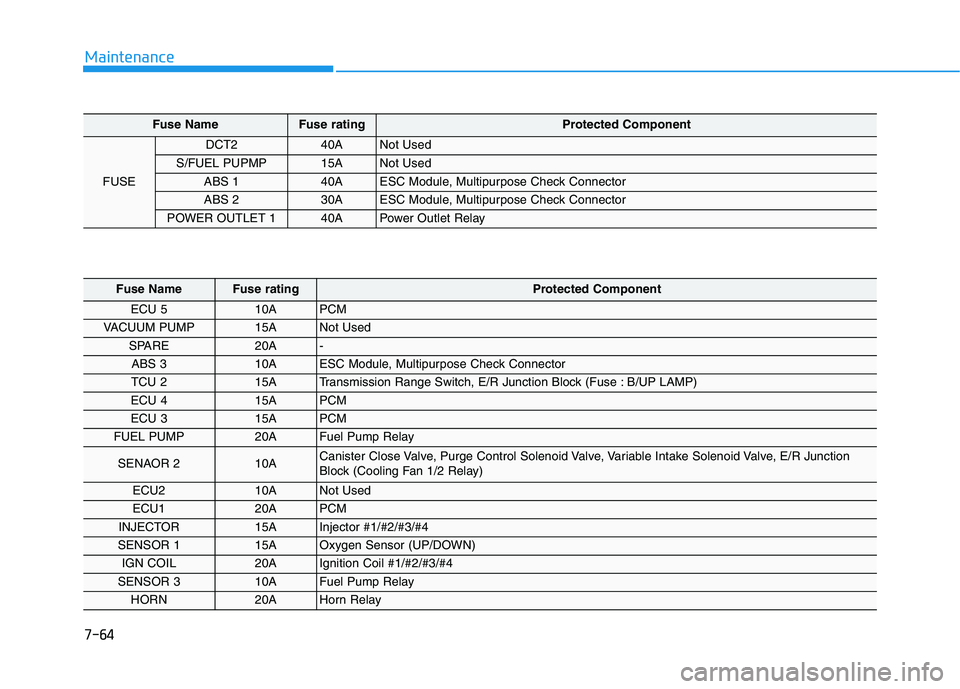
Fuse NameFuse rating Protected Component
FUSE
DCT2 40A Not Used
S/FUEL PUPMP 15A Not Used
ABS 1 40A ESC Module, Multipurpose Check Connector
ABS 2 30A ESC Module, Multipurpose Check Connector
POWER OUTLET 1 40A Power Outlet Relay
Fuse Name Fuse rating Protected Component
ECU 5 10A PCM
VACUUM PUMP 15A Not Used
SPARE 20A -
ABS 3 10A ESC Module, Multipurpose Check Connector
TCU 2 15A Transmission Range Switch, E/R Junction Block (Fuse : B/UP LAMP)
ECU 4 15A PCM
ECU 3 15A PCM
FUEL PUMP 20A Fuel Pump Relay
SENAOR 2 10A Canister Close Valve, Purge Control Solenoid Valve, Variable Intake Solenoid Valve, E/R Junction
Block (Cooling Fan 1/2 Relay)
ECU2 10A Not Used
ECU1 20A PCM
INJECTOR 15A Injector #1/#2/#3/#4
SENSOR 1 15A Oxygen Sensor (UP/DOWN)
IGN COIL 20A Ignition Coil #1/#2/#3/#4
SENSOR 3 10A Fuel Pump Relay
HORN 20A Horn Relay
Page 490 of 534
7-65
7
Maintenance
LLIIGG HH TT BB UU LLBB SS
Consult an authorized HYUNDAI
dealer to replace most vehicle light
bulbs. It is difficult to replace vehicle
light bulbs because other parts of the
vehicle must be removed before you
can get to the bulb. This is especially
true for removing the headlamp
assembly to get to the bulb(s).
Removing/installing the headlamp
assembly can result in damage to
the vehicle.
Information
After heavy driving, rain or washing,
headlamp and trunk lenses could
appear frosty. This condition is caused
by the temperature difference
between the lamp inside and the out-
side temperature. This is similar to the
condensation on your windows inside
your vehicle during the rain and does-
n ’t indicate a problem with your vehi-
cle. If the water leaks into the lamp
bulb circuitry, have your vehicle
checked by an authorized HYUNDAI
dealer.Headlamp, Parking Lamp, Turn Signal Lamp and Side Marker
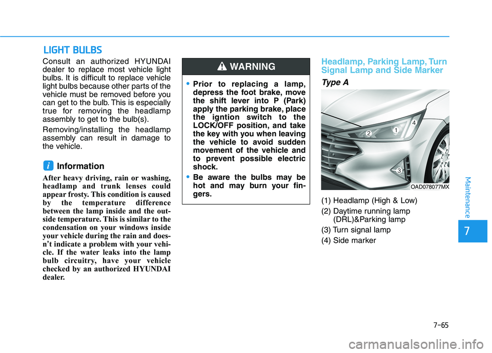
Type A
(1) Headlamp (High & Low)
(2) Daytime running lamp (DRL)&Parking lamp
(3) Turn signal lamp
(4) Side marker
i
Prior to replacing a lamp,
depress the foot brake, move
the shift lever into P (Park)
apply the parking brake, place
the igntion switch to the
LOCK/OFF position, and take
the key with you when leaving
the vehicle to avoid sudden
movement of the vehicle and
to prevent possible electric
shock.
Be aware the bulbs may be
hot and may burn your fin-
gers.
WARNING
OAD078077MX