Hyundai Genesis Coupe 2013 Owner's Manual
Manufacturer: HYUNDAI, Model Year: 2013, Model line: Genesis Coupe, Model: Hyundai Genesis Coupe 2013Pages: 414, PDF Size: 38.89 MB
Page 381 of 414
Maintenance
74
7
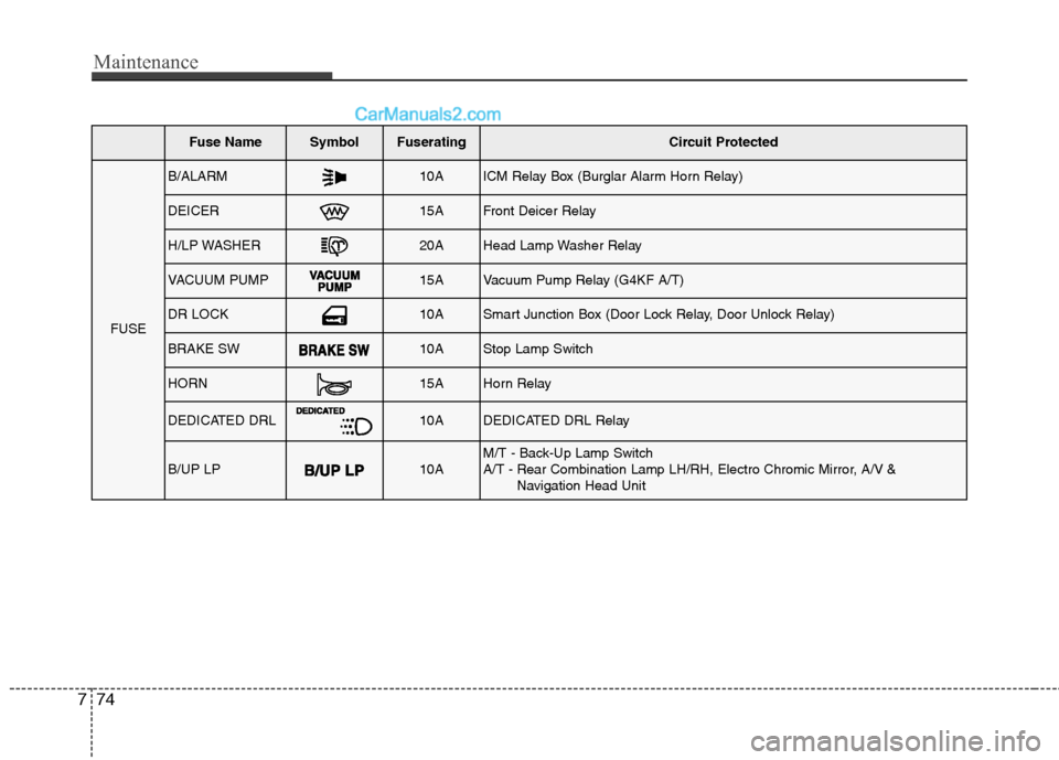
Fuse NameSymbolFuseratingCircuit Protected
FUSE
B/ALARM10AICM Relay Box (Burglar Alarm Horn Relay)
DEICER15AFront Deicer Relay
H/LP WASHER20AHead Lamp Washer Relay
VACUUM PUMP15AVacuum Pump Relay (G4KF A/T)
DR LOCK10ASmart Junction Box (Door Lock Relay, Door Unlock Relay)
BRAKE SW10AStop Lamp Switch
HORN15AHorn Relay
DEDICATED DRL10ADEDICATED DRL Relay
B/UP LP10AM/T - Back-Up Lamp Switch
A/T - Rear Combination Lamp LH/RH, Electro Chromic Mirror, A/V &
Navigation Head Unit
Page 382 of 414
775
Maintenance
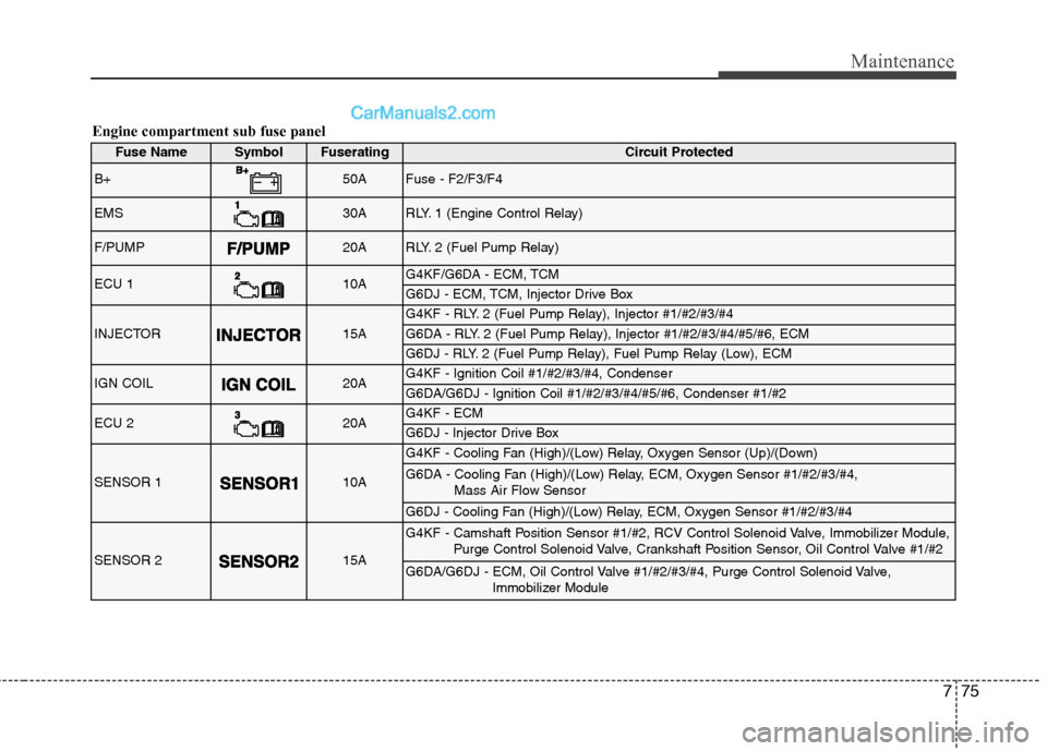
Engine compartment sub fuse panel
Fuse NameSymbolFuseratingCircuit Protected
B+50AFuse - F2/F3/F4
EMS30ARLY. 1 (Engine Control Relay)
F/PUMP20ARLY. 2 (Fuel Pump Relay)
ECU 110AG4KF/G6DA - ECM, TCM
G6DJ - ECM, TCM, Injector Drive Box
INJECTOR15A
G4KF - RLY. 2 (Fuel Pump Relay), Injector #1/#2/#3/#4
G6DA - RLY. 2 (Fuel Pump Relay), Injector #1/#2/#3/#4/#5/#6, ECM
G6DJ - RLY. 2 (Fuel Pump Relay), Fuel Pump Relay (Low), ECM
IGN COIL20AG4KF - Ignition Coil #1/#2/#3/#4, Condenser
G6DA/G6DJ - Ignition Coil #1/#2/#3/#4/#5/#6, Condenser #1/#2
ECU 220AG4KF - ECM
G6DJ - Injector Drive Box
SENSOR 110A
G4KF - Cooling Fan (High)/(Low) Relay, Oxygen Sensor (Up)/(Down)
G6DA - Cooling Fan (High)/(Low) Relay, ECM, Oxygen Sensor #1/#2/#3/#4, Mass Air Flow Sensor
G6DJ - Cooling Fan (High)/(Low) Relay, ECM, Oxygen Sensor #1/#2/#3/#4
SENSOR 215A
G4KF - Camshaft Position Sensor #1/#2, RCV Control Solenoid Valve, Immobilizer Module,Purge Control Solenoid Valve, Crankshaft Position Sensor, Oil Control Valve #1/#2
G6DA/G6DJ - ECM, Oil Control Valve #1/#2/#3/#4, Purge Control Solenoid Valve, Immobilizer Module
Page 383 of 414
Maintenance
76
7
LIGHT BULBS
Use only the bulbs of the specified
wattage.
✽✽ NOTICE
After heavy, driving rain or washing, headlight and taillight lenses could
appear frosty. This condition is caused
by the temperature difference between
the lamp inside and outside. This is sim-
ilar to the condensation on your win-
dows inside your vehicle during the rain
and doesn’t indicate a problem with
your vehicle. If the water leaks into the
lamp bulb circuitry, we recommend thatthe system be checked by an authorized
HYUNDAI dealer.
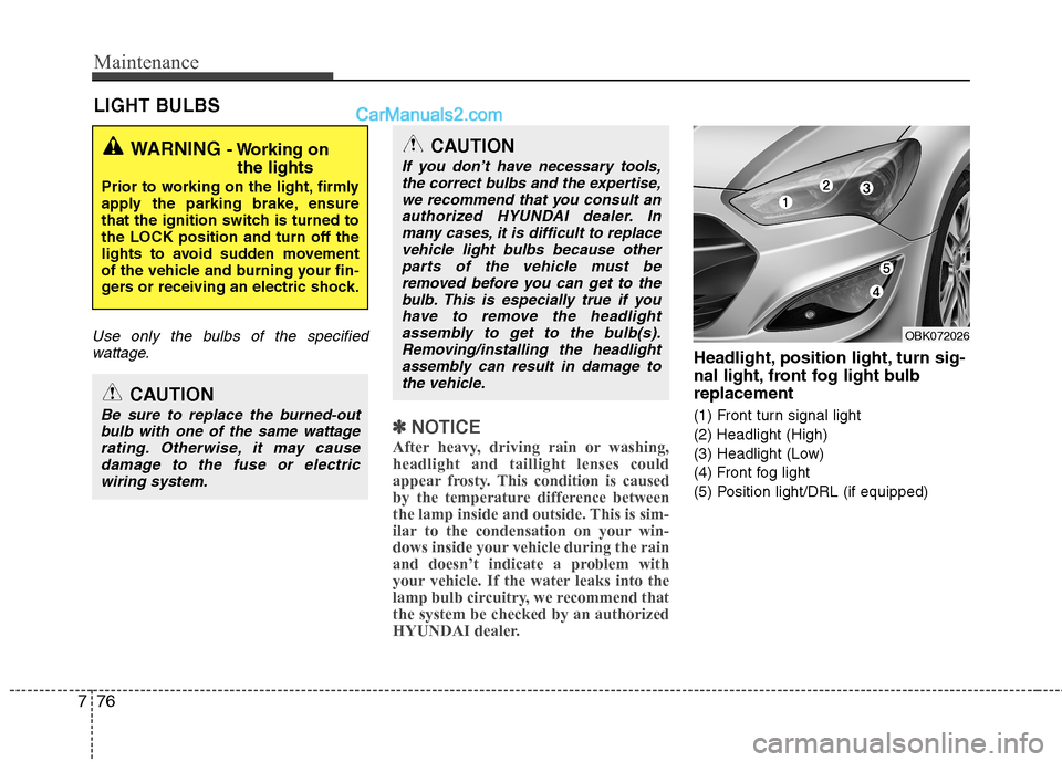
Headlight, position light, turn sig-
nal light, front fog light bulbreplacement
(1) Front turn signal light
(2) Headlight (High)
(3) Headlight (Low)
(4) Front fog light
(5) Position light/DRL (if equipped)
WARNING - Working on
the lights
Prior to working on the light, firmly
apply the parking brake, ensure
that the ignition switch is turned tothe LOCK position and turn off the
lights to avoid sudden movement
of the vehicle and burning your fin-
gers or receiving an electric shock.
CAUTION
Be sure to replace the burned-out bulb with one of the same wattagerating. Otherwise, it may causedamage to the fuse or electric wiring system.
CAUTION
If you don’t have necessary tools,the correct bulbs and the expertise,
we recommend that you consult anauthorized HYUNDAI dealer. Inmany cases, it is difficult to replace vehicle light bulbs because other
parts of the vehicle must beremoved before you can get to thebulb. This is especially true if you
have to remove the headlightassembly to get to the bulb(s).Removing/installing the headlightassembly can result in damage to
the vehicle.
OBK072026
Page 384 of 414
777
Maintenance
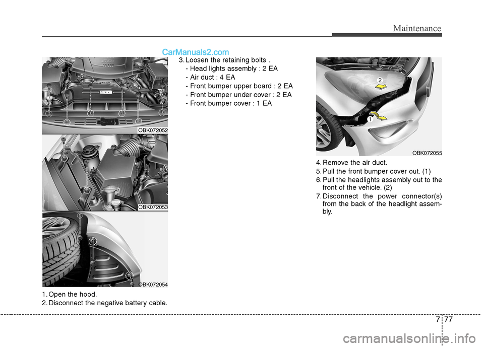
1. Open the hood.
2. Disconnect the negative battery cable.3. Loosen the retaining bolts .
- Head lights assembly : 2 EA
- Air duct : 4 EA
- Front bumper upper board : 2 EA
- Front bumper under cover : 2 EA
- Front bumper cover : 1 EA
4. Remove the air duct.
5. Pull the front bumper cover out. (1)
6. Pull the headlights assembly out to thefront of the vehicle. (2)
7. Disconnect the power connector(s) from the back of the headlight assem-
bly.
OBK072052
OBK072053
OBK072054
OBK072055
Page 385 of 414
Maintenance
78
7
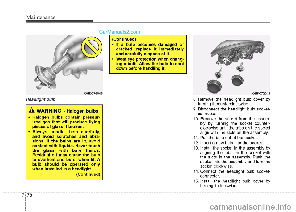
Headlight bulb8. Remove the headlight bulb cover by
turning it counterclockwise.
9. Disconnect the headlight bulb socket- connector.
10. Remove the socket from the assem- bly by turning the socket counter-
clockwise until the tabs on the socket
align with the slots on the assembly.
11. Pull the bulb out of the socket.
12. Insert a new bulb into the socket.
13. Install the socket in the assembly by aligning the tabs on the socket with
the slots in the assembly. Push the
socket into the assembly and turn the
socket clockwise.
14. Connect the headlight bulb socket- connector.
15. Install the headlight bulb cover by turning it clockwise.
(Continued)
If a bulb becomes damaged or
cracked, replace it immediately
and carefully dispose of it.
Wear eye protection when chang- ing a bulb. Allow the bulb to cool
down before handling it.
OBK072045OHD076046
WARNING - Halogen bulbs
Halogen bulbs contain pressur-
ized gas that will produce flying
pieces of glass if broken.
Always handle them carefully, and avoid scratches and abra-
sions. If the bulbs are lit, avoid
contact with liquids. Never touchthe glass with bare hands.
Residual oil may cause the bulb
to overheat and burst when lit. A
bulb should be operated onlywhen installed in a headlight.
(Continued)
Page 386 of 414
779
Maintenance
✽✽NOTICE
If the headlight aiming adjustment is
necessary after the headlight assembly is
reinstalled, we recommend that you con-
sult an authorized HYUNDAI dealer.
❋❋ Traffic Change (For Europe)
The low beam light distribution is asym-
metric.
If you go abroad to a country with oppo-
site traffic direction, this asymmetric part
will dazzle oncoming car driver. To pre-
vent dazzle, these headlamps are
designed not to dazzle opposite drivers.
So, you need not change your head-
lamps in a country with opposite trafficdirection.
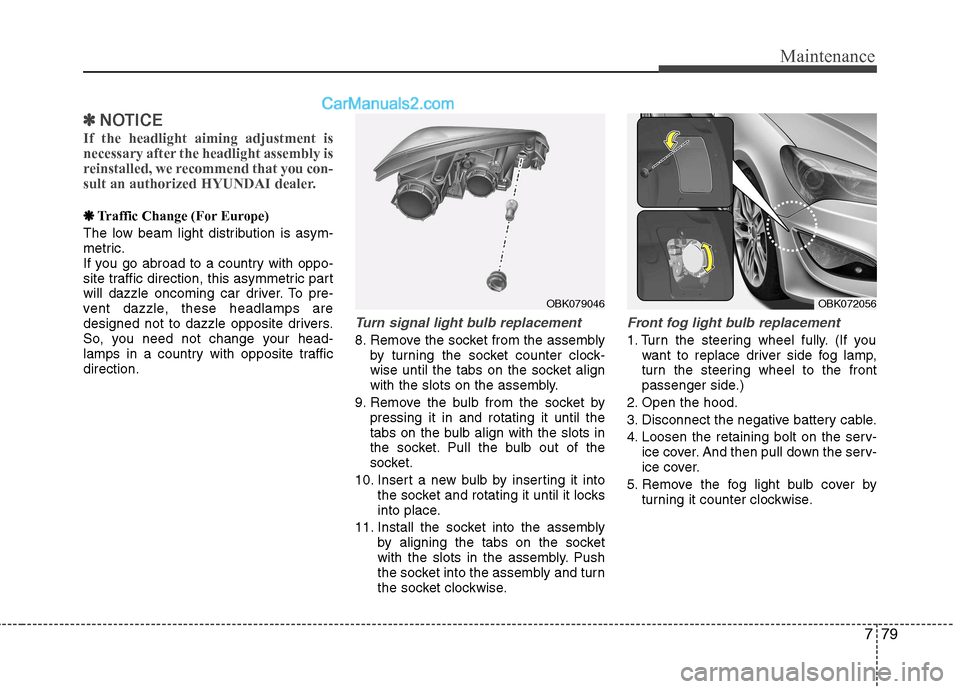
Turn signal light bulb replacement
8. Remove the socket from the assembly by turning the socket counter clock-
wise until the tabs on the socket align
with the slots on the assembly.
9. Remove the bulb from the socket by pressing it in and rotating it until the
tabs on the bulb align with the slots in
the socket. Pull the bulb out of the
socket.
10. Insert a new bulb by inserting it into the socket and rotating it until it locks
into place.
11. Install the socket into the assembly by aligning the tabs on the socket
with the slots in the assembly. Push
the socket into the assembly and turn
the socket clockwise.
Front fog light bulb replacement
1. Turn the steering wheel fully. (If youwant to replace driver side fog lamp,
turn the steering wheel to the front
passenger side.)
2. Open the hood.
3. Disconnect the negative battery cable.
4. Loosen the retaining bolt on the serv- ice cover. And then pull down the serv-
ice cover.
5. Remove the fog light bulb cover by turning it counter clockwise.
OBK079046OBK072056
Page 387 of 414
Maintenance
80
7
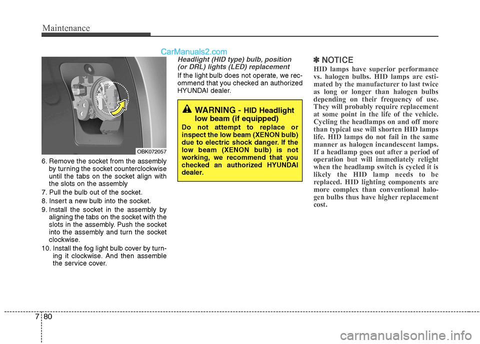
6. Remove the socket from the assembly
by turning the socket counterclockwise
until the tabs on the socket align with
the slots on the assembly
7. Pull the bulb out of the socket.
8. Insert a new bulb into the socket.
9. Install the socket in the assembly by aligning the tabs on the socket with the
slots in the assembly. Push the socket
into the assembly and turn the socket
clockwise.
10. Install the fog light bulb cover by turn- ing it clockwise. And then assemble
the service cover.
Headlight (HID type) bulb, position
(or DRL) lights (LED) replacement
If the light bulb does not operate, we rec-
ommend that you checked an authorized
HYUNDAI dealer.
✽✽ NOTICE
HID lamps have superior performance
vs. halogen bulbs. HID lamps are esti-
mated by the manufacturer to last twice
as long or longer than halogen bulbs
depending on their frequency of use.
They will probably require replacementat some point in the life of the vehicle.
Cycling the headlamps on and off morethan typical use will shorten HID lampslife. HID lamps do not fail in the same
manner as halogen incandescent lamps.
If a headlamp goes out after a period of
operation but will immediately relightwhen the headlamp switch is cycled it islikely the HID lamp needs to be
replaced. HID lighting components are
more complex than conventional halo-
gen bulbs thus have higher replacementcost.
OBK072057
WARNING - HID Headlight
low beam (if equipped)
Do not attempt to replace or
inspect the low beam (XENON bulb)
due to electric shock danger. If the
low beam (XENON bulb) is not
working, we recommend that you
checked an authorized HYUNDAI
dealer.
Page 388 of 414
781
Maintenance
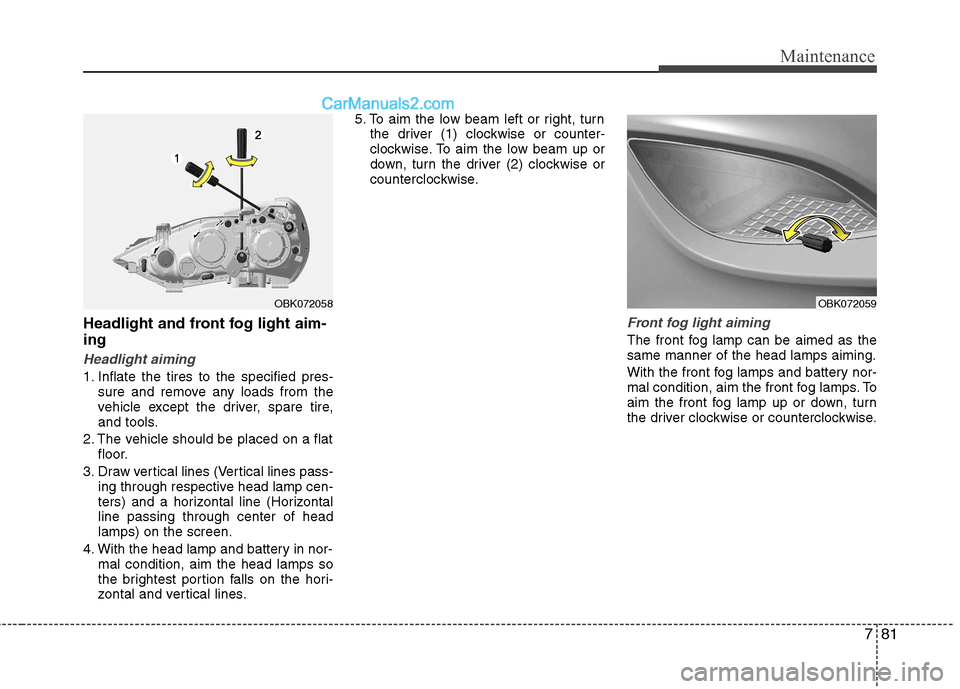
Headlight and front fog light aim- ing
Headlight aiming
1. Inflate the tires to the specified pres-sure and remove any loads from the
vehicle except the driver, spare tire,
and tools.
2. The vehicle should be placed on a flat floor.
3. Draw vertical lines (Vertical lines pass- ing through respective head lamp cen-
ters) and a horizontal line (Horizontalline passing through center of headlamps) on the screen.
4. With the head lamp and battery in nor- mal condition, aim the head lamps so
the brightest portion falls on the hori-
zontal and vertical lines. 5. To aim the low beam left or right, turn
the driver (1) clockwise or counter-
clockwise. To aim the low beam up or
down, turn the driver (2) clockwise or
counterclockwise.
Front fog light aiming
The front fog lamp can be aimed as the same manner of the head lamps aiming.
With the front fog lamps and battery nor-
mal condition, aim the front fog lamps. To
aim the front fog lamp up or down, turn
the driver clockwise or counterclockwise.
OBK072058OBK072059
Page 389 of 414
Maintenance
82
7
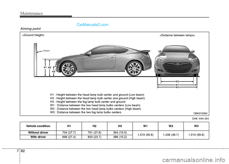
Vehicle condition H1 H2 H3 W1 W2 W3
Without driver 704 (27.7) 701 (27.6) 394 (15.5)
1,519 (59.8) 1,238 (48.7) 1,519 (59.8)
With driver 696 (27.4) 603 (23.7) 386 (15.2)
Unit: mm (in)
H1 : Height between the head lamp bulb center and ground (Low beam)
H2 : Height between the head lamp bulb center and ground (High beam)
H3 : Height between the fog lamp bulb center and ground
W1 : Distance between the two head lamp bulbs centers (Low beam)
W2 : Distance between the two head lamp bulbs centers (High beam)
W3 : Distance between the two fog lamp bulbs centers
Aiming point
OBK072060
Page 390 of 414
783
Maintenance
OMD051054L
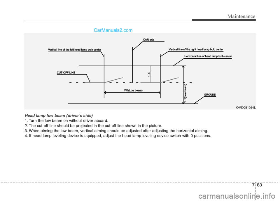
Head lamp low beam (driver’s side)
1. Turn the low beam on without driver aboard.
2. The cut-off line should be projected in the cut-off line shown in the picture.
3. When aiming the low beam, vertical aiming should be adjusted after adjusting the horizontal aiming.
4. If head lamp leveling device is equipped, adjust the head lamp leveling device switch with 0 positions.