brake Hyundai Genesis Coupe 2013 Owner's Manual
[x] Cancel search | Manufacturer: HYUNDAI, Model Year: 2013, Model line: Genesis Coupe, Model: Hyundai Genesis Coupe 2013Pages: 414, PDF Size: 38.89 MB
Page 5 of 414
15
Introduction
VEHICLE BREAK-IN PROCESS
No special break-in period is needed. By
following a few simple precautions for the
first 1,000 km (600 miles) you may add to
the performance, economy and life of
your vehicle.
Do not race the engine.
While driving, keep your engine speed(rpm, or revolutions per minute)
between 2,000 rpm and 4,000 rpm.
Do not maintain a single speed for long periods of time, either fast or slow.
Varying engine speed is needed to
properly break-in the engine.
Avoid hard stops, except in emergen- cies, to allow the brakes to seat prop-
erly.
Don't let the engine idle longer than 3 minutes at one time.
Don't tow a trailer during the first 2,000 km (1,200 miles) of operation.
Page 6 of 414
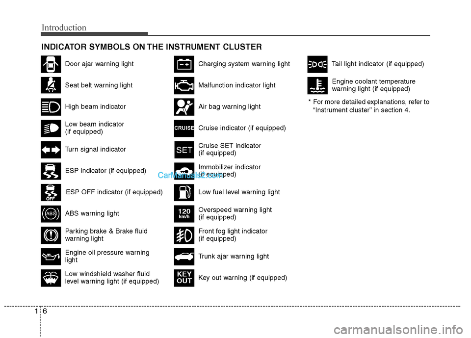
INDICATOR SYMBOLS ON THE INSTRUMENT CLUSTER
Seat belt warning light
High beam indicator
Turn signal indicator
ABS warning light
Parking brake & Brake fluid
warning light
Engine oil pressure warning light
ESP indicator (if equipped)
ESP OFF indicator (if equipped)
Malfunction indicator light
Air bag warning light
Cruise indicator (if equipped)
Cruise SET indicator (if equipped)
Immobilizer indicator (if equipped)
Low fuel level warning light* For more detailed explanations, refer to
“Instrument cluster” in section 4.
Charging system warning light
Low windshield washer fluid
level warning light (if equipped)
Door ajar warning light
Overspeed warning light (if equipped)
120km/h
Key out warning (if equipped) KEY
OUT
Trunk ajar warning light
Front fog light indicator (if equipped)
Tail light indicator (if equipped)
Low beam indicator (if equipped) Engine coolant temperature
warning light (if equipped)
16
Introduction
Page 10 of 414
Your vehicle at a glance
4
2
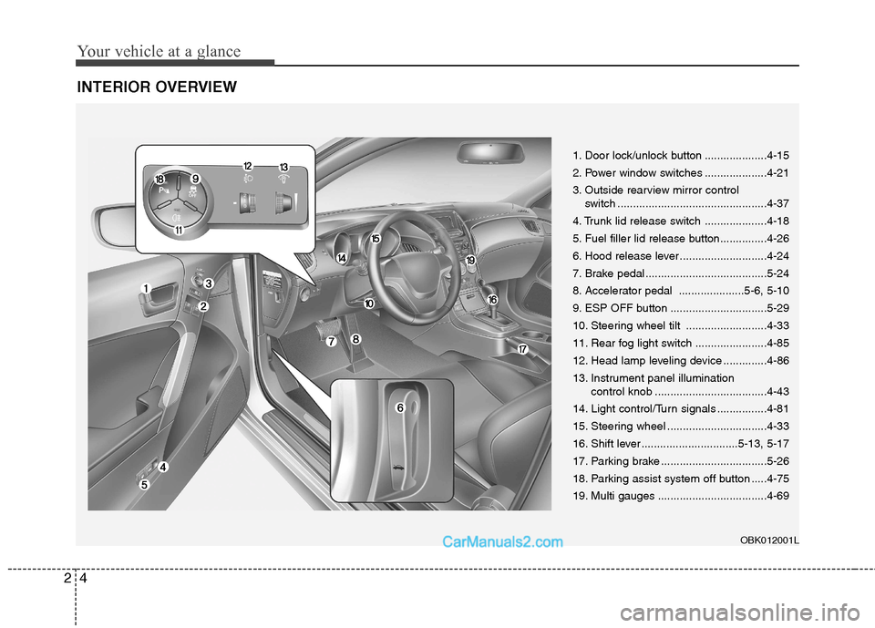
INTERIOR OVERVIEW
1. Door lock/unlock button ....................4-15
2. Power window switches ....................4-21
3. Outside rearview mirror control
switch ................................................4-37
4. Trunk lid release switch ....................4-18
5. Fuel filler lid release button...............4-26
6. Hood release lever ............................4-24
7. Brake pedal .......................................5-24
8. Accelerator pedal .....................5-6, 5-10
9. ESP OFF button ...............................5-29
10. Steering wheel tilt ..........................4-33
11. Rear fog light switch .......................4-85
12. Head lamp leveling device ..............4-86
13. Instrument panel illumination control knob ....................................4-43
14. Light control/Turn signals ................4-81
15. Steering wheel ................................4-33
16. Shift lever ...............................5-13, 5-17
17. Parking brake ..................................5-26
18. Parking assist system off button .....4-75
19. Multi gauges ...................................4-69
OBK012001L
Page 11 of 414
25
Your vehicle at a glance
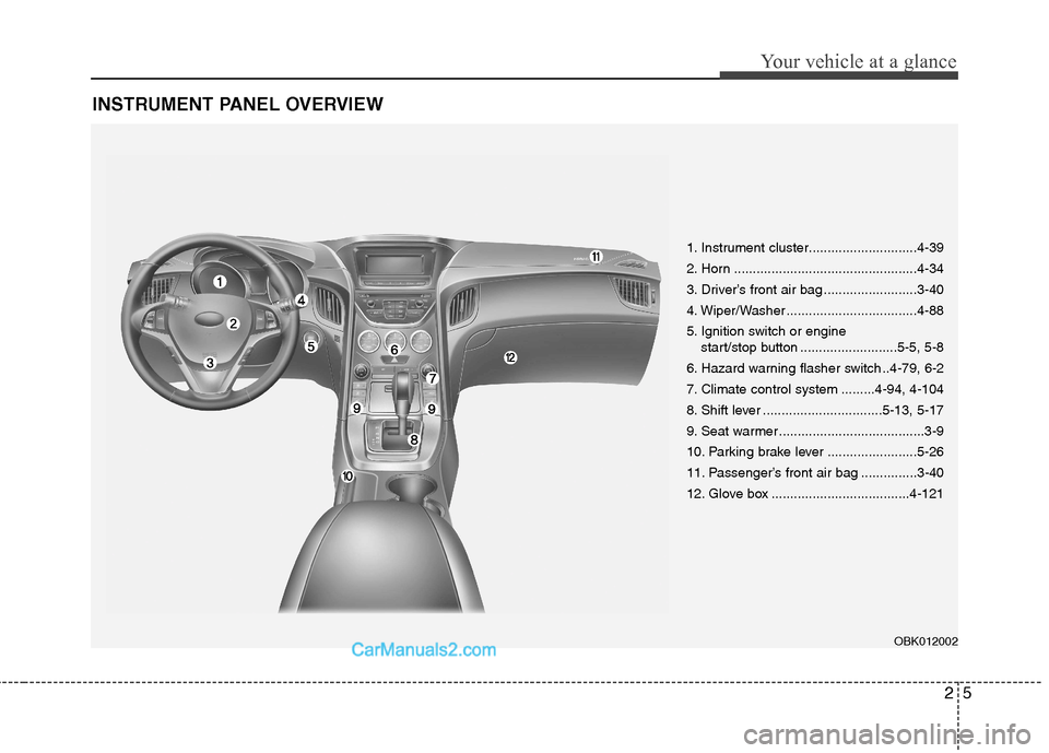
INSTRUMENT PANEL OVERVIEW
1. Instrument cluster.............................4-39
2. Horn .................................................4-34
3. Driver’s front air bag .........................3-40
4. Wiper/Washer ...................................4-88
5. Ignition switch or engine start/stop button ..........................5-5, 5-8
6. Hazard warning flasher switch ..4-79, 6-2
7. Climate control system .........4-94, 4-104
8. Shift lever ................................5-13, 5-17
9. Seat warmer .......................................3-9
10. Parking brake lever ........................5-26
11. Passenger’s front air bag ...............3-40
12. Glove box .....................................4-121
OBK012002
Page 12 of 414
Your vehicle at a glance
6
2
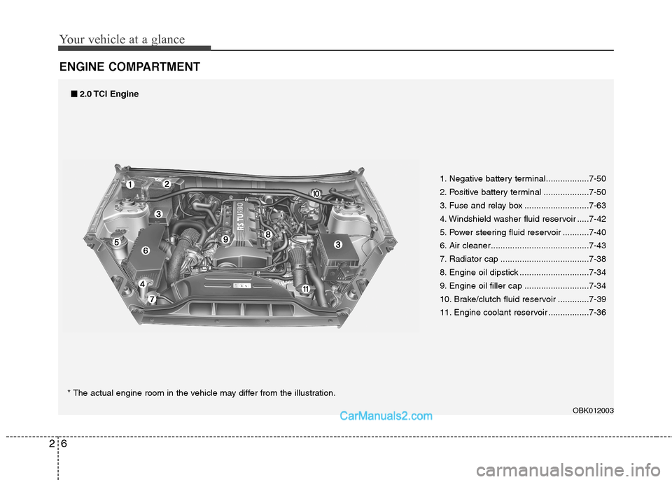
ENGINE COMPARTMENT
1. Negative battery terminal..................7-50
2. Positive battery terminal ...................7-50
3. Fuse and relay box ...........................7-63
4. Windshield washer fluid reservoir .....7-42
5. Power steering fluid reservoir ...........7-40
6. Air cleaner.........................................7-43
7. Radiator cap .....................................7-38
8. Engine oil dipstick .............................7-34
9. Engine oil filler cap ...........................7-34
10. Brake/clutch fluid reservoir .............7-39
11. Engine coolant reservoir .................7-36
OBK012003
■■2.0 TCI Engine
* The actual engine room in the vehicle may differ from the illustration.
Page 13 of 414
27
Your vehicle at a glance
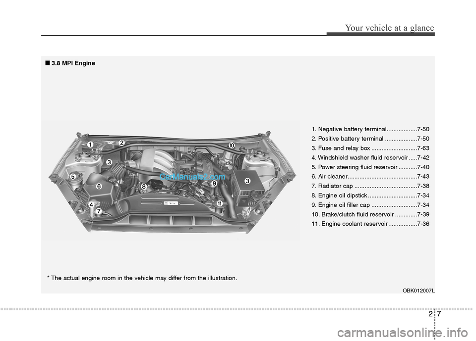
1. Negative battery terminal..................7-50
2. Positive battery terminal ...................7-50
3. Fuse and relay box ...........................7-63
4. Windshield washer fluid reservoir .....7-42
5. Power steering fluid reservoir ...........7-40
6. Air cleaner.........................................7-43
7. Radiator cap .....................................7-38
8. Engine oil dipstick .............................7-34
9. Engine oil filler cap ...........................7-34
10. Brake/clutch fluid reservoir .............7-39
11. Engine coolant reservoir .................7-36
■
■
3.8 MPI Engine
* The actual engine room in the vehicle may differ from the illustration.
OBK012007L
Page 14 of 414
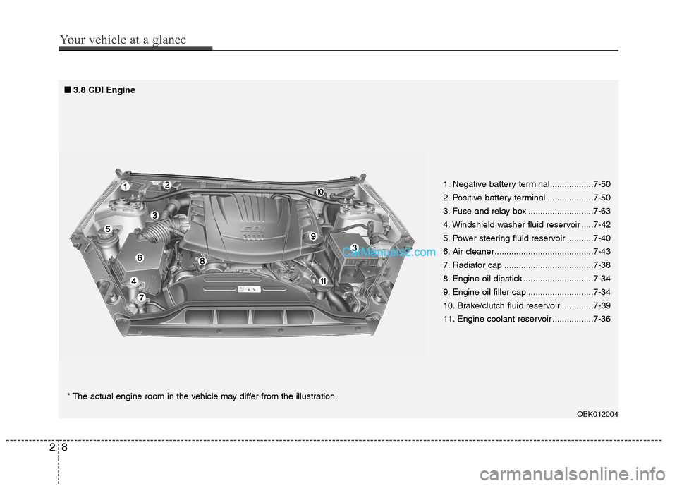
1. Negative battery terminal..................7-50
2. Positive battery terminal ...................7-50
3. Fuse and relay box ...........................7-63
4. Windshield washer fluid reservoir .....7-42
5. Power steering fluid reservoir ...........7-40
6. Air cleaner.........................................7-43
7. Radiator cap .....................................7-38
8. Engine oil dipstick .............................7-34
9. Engine oil filler cap ...........................7-34
10. Brake/clutch fluid reservoir .............7-39
11. Engine coolant reservoir .................7-36
■
■
3.8 GDI Engine
* The actual engine room in the vehicle may differ from the illustration.
OBK012004
28
Your vehicle at a glance
Page 28 of 414
Safety features of your vehicle
14
3
WARNING - Cargo
Cargo should always be secured to
prevent it from being thrown about
the vehicle in a collision and caus-
ing injury to the vehicle occupants.Special care should be taken ofobjects placed in the rear seats,
since those may hit the front seat
occupants in a frontal collision.CAUTION - Rear seat belts
When returning the rear seatbacks
to the upright position, remember
to return the rear shoulder belt toits proper position.
After returning the rear seatbacks to the upright position, check that
the rearseats are secure.
CAUTION
Make sure the engine is off, the automatic transmission is in Pand the parking brake is appliedwhenever loading or unloading
cargo. The Vehicle may move ifthe shift lever is inadvertently moved to another position.
Be careful when loading cargo through the rear passenger seats
to prevent damage to the vehicle interior.
When cargo is loaded through the rear passenger seats, ensure thecargo is properly secured to pre-
vent it from moving while driving.Unsecured cargo in the passen-ger compartment can cause dam-
age to the vehicle or injury to it’soccupants.
Page 63 of 414
349
Safety features of your vehicle
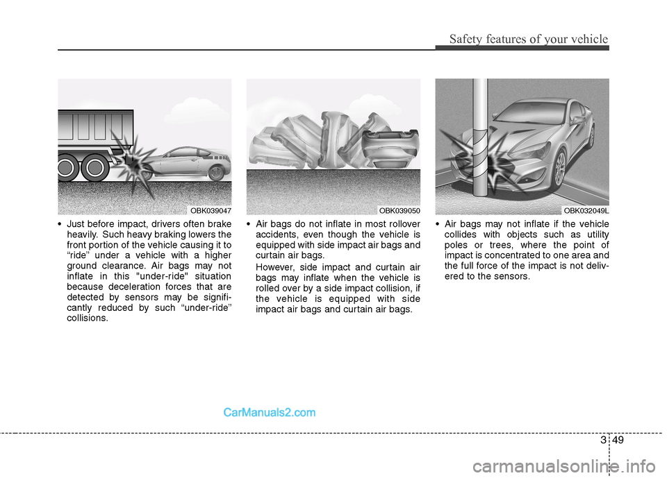
Just before impact, drivers often brakeheavily. Such heavy braking lowers the
front portion of the vehicle causing it to
“ride” under a vehicle with a higher
ground clearance. Air bags may not
inflate in this "under-ride" situation
because deceleration forces that are
detected by sensors may be signifi-
cantly reduced by such “under-ride”
collisions. Air bags do not inflate in most rollover
accidents, even though the vehicle isequipped with side impact air bags and
curtain air bags.
However, side impact and curtain air bags may inflate when the vehicle is
rolled over by a side impact collision, if
the vehicle is equipped with side
impact air bags and curtain air bags. Air bags may not inflate if the vehicle
collides with objects such as utility
poles or trees, where the point of
impact is concentrated to one area and
the full force of the impact is not deliv-
ered to the sensors.
OBK039047OBK039050OBK032049L
Page 81 of 414
415
Features of your vehicle
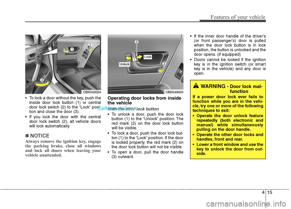
To lock a door without the key, push theinside door lock button (1) or central
door lock switch (2 ) to the “Lock” posi-
tion and close the door (3).
If you lock the door with the central door lock switch (2), all vehicle doors
will lock automatically.
✽✽ NOTICE
Always remove the ignition key, engage the parking brake, close all windowsand lock all doors when leaving yourvehicle unattended.
Operating door locks from inside
the vehicle
With the door lock button
To unlock a door, push the door lock button (1) to the “Unlock” position. The
red mark (2) on the door lock button
will be visible.
To lock a door, push the door lock but- ton (1) to the “Lock” position. If the door
is locked properly, the red mark (2) on
the door lock button will not be visible.
To open a door, pull the door handle (3) outward. If the inner door handle of the driver’s
(or front passenger’s) door is pulled
when the door lock button is in lock
position, the button is unlocked and the
door opens. (if equipped)
Doors cannot be locked if the ignition key is in the ignition switch (or smart
key is in the vehicle) and any door isopen.
OBK049005
Lock
Unlock
WARNING - Door lock mal-
function
If a power door lock ever fails to
function while you are in the vehi-
cle, try one or more of the following
techniques to exit:
Operate the door unlock feature repeatedly (both electronic and
manual) while simultaneously
pulling on the door handle.
Operate the other door locks and handles, front and rear.
Lower a front window and use the key to unlock the door from out-
side.
OBK042004