horn Hyundai Getz 2007 Owner's Manual
[x] Cancel search | Manufacturer: HYUNDAI, Model Year: 2007, Model line: Getz, Model: Hyundai Getz 2007Pages: 463, PDF Size: 11.14 MB
Page 9 of 463

YOUR VEHICLE AT A GLANCE
F9
1. Headlight Leveling Switch (If installed)
2. Front Fog Light Switch (If installed)
3. Multi-Function Light Switch
4. Instrument Cluster
5. Horn and Driver's Airbag (If installed)
6. Windshield Wiper/Washer Switch
7. Digital Clock
8. Hazard Warning Light
9. Audio System (If installed)
10. Passenger's Airbag (If installed)
11. Glove Box
CAUTION:
When installing a container of liquid air freshener inside a vehicle, do not place it near the instrument cluster nor on the instrument panel pad surface. If there is any leakage from the air freshener onto these areas (instrument cluster, instrument panel pad or air ventilator), it may damage these parts.If the liquid from the air freshener doesleak onto these areas, wash them with water immediately. 12. Hood Release Lever
13. Fuse Box
14. Audio Remote Control Switch (If installed)
15. Heating/Air Conditioning Control Panel
(If installed)
16. Cigarette Lighter
17. Ashtray
18. Front Drink Holder
19. Shift Lever (If installed)
20. Parking Brake Lever
21. Rear Drink Holder
!
Page 11 of 463

YOUR VEHICLE AT A GLANCE
F11
1. Glove Box
2. Passenger's Airbag (If installed)
3. Audio System (If installed)
4. Hazard Warning Light
5. Digital Clock
6. Windshield Wiper/Washer Switch
7. Horn and Driver's Airbag (If installed)
8. Instrument Cluster
9. Multi-Function Light Switch
10. Headlight Leveling Switch (If installed)
11. Rear Drink Holder
CAUTION:
When installing a container of liquid air freshener inside a vehicle, do not place it near the instrument cluster nor on the instrument panel pad surface. If there is any leakage from the air freshener onto these areas (instrument cluster, instrument panel pad or air ventilator), it may damage these parts. If the liquid from the air freshener does leak onto these areas, wash them with water immediately. 12. Parking Brake Lever
13. Shift Lever (If installed)
14. Front Drink Holder
15. Ashtray
16. Power Outlet (If installed)
17. Heating/Air Conditioning Control Panel
(If installed)
18. Audio Remote Control Switch (If installed)
19. Fuse Box
20. Hood Release Lever
!
Page 22 of 463

1- 10 FEATURES OF YOUR HYUNDAI
HTB202
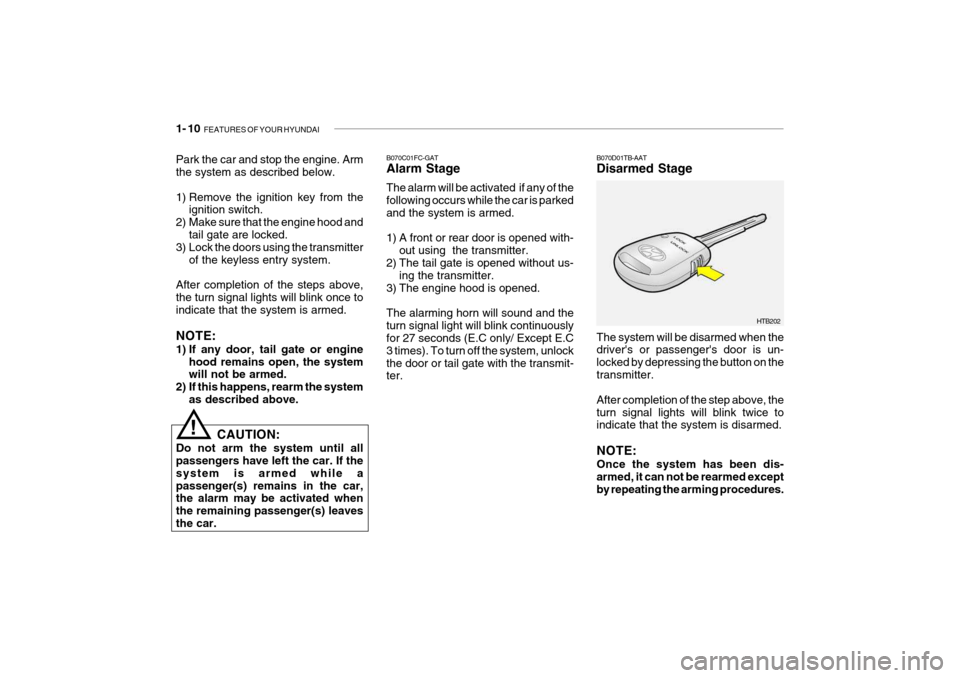
B070D01TB-AAT Disarmed Stage
B070C01FC-GATAlarm Stage The alarm will be activated if any of the following occurs while the car is parkedand the system is armed.
1) A front or rear door is opened with-
out using the transmitter.
2) The tail gate is opened without us-
ing the transmitter.
3) The engine hood is opened.The alarming horn will sound and the turn signal light will blink continuously for 27 seconds (E.C only/ Except E.C 3 times). To turn off the system, unlockthe door or tail gate with the transmit- ter. The system will be disarmed when thedriver's or passenger's door is un- locked by depressing the button on thetransmitter. After completion of the step above, the turn signal lights will blink twice to indicate that the system is disarmed. NOTE: Once the system has been dis- armed, it can not be rearmed except by repeating the arming procedures.
Park the car and stop the engine. Armthe system as described below.
1) Remove the ignition key from the
ignition switch.
2) Make sure that the engine hood and tail gate are locked.
3) Lock the doors using the transmitter
of the keyless entry system.
After completion of the steps above, the turn signal lights will blink once toindicate that the system is armed. NOTE:
1) If any door, tail gate or engine hood remains open, the system will not be armed.
2) If this happens, rearm the system
as described above.
CAUTION:
Do not arm the system until allpassengers have left the car. If the system is armed while apassenger(s) remains in the car, the alarm may be activated when the remaining passenger(s) leavesthe car.
!
Page 96 of 463

1- 84 FEATURES OF YOUR HYUNDAI
B610B01A-GAT HORN
Press the center hub of the steering wheel to sound the horn. B240B01TBB600A01A-AAT STEERING WHEEL TILT LEVER (If Installed)To Adjust the Steering Wheel:
B600A01TB
1. Push the lever downward to unlock.
2. Raise or lower the steering wheel to the desired position.
3. After adjustment, securely tighten the lever by pulling it upward.
!WARNING:
Do not attempt to adjust the steer- ing wheel while driving as this may result in loss of control of the ve-hicle which may cause serious in- jury or death.
Your Hyundai is equipped with sunvisors to give the driver and front pas- senger either frontal or side ward shade.The sun visors are fitted on both sides on all models. To reduce glare or to shut out direct rays of the sun, turn thesun visor down to block the annoy- ance. A ticket holder is provided on the back of the sun visor for the driver.Vanity mirrors are provided on the back of the sunvisor for the driver and the front passenger (If installed). NOTE: The Supplemental Restraint Sys- tem (SRS) label containing useful information can be found on the front of each sun visor.
WARNING:
Do not place the sun visor in sucha manner that it obscures visibilityof the roadway, traffic or other ob- jects.
!
Page 200 of 463

DO-IT-YOURSELF MAINTENANCE 6- 5
G020A02A-AAT GENERAL CHECKS Engine Compartment The following should be checked regu-larly:
o Engine oil level and condition
o Transaxle fluid level and condition
o Brake fluid level
o Clutch fluid level
o Engine coolant level
o Windshield washer fluid level
o Accessory drive belt condition
o Engine coolant hose condition
o Fluid leaks (on or below compo-
nents)
o Power steering fluid level
o Battery condition
o Air filter condition G020C01A-AAT Vehicle Interior The following should be checked each time when the vehicle is driven:
o Lights operation
o Windshield wiper operation
o Horn operation
o Defroster, heater system operation
(and air conditioning, if installed)
o Steering operation and condition
o Mirror condition and operation
o Turn signal operation
o Accelerator pedal operation
o Brake operation, including parking brake
o Manual transaxle operation, includ- ing clutch operation
o Automatic transaxle operation, in- cluding "Park" mechanism opera-tion
o Seat control condition and opera- tion
o Seat belt condition and operation
o Sunvisor operation If you notice anything that does not operate correctly or appears to befunctioning incorrectly, inspect it care- fully and seek assistance from your Hyundai dealer if service is needed.
G020B01A-AAT Vehicle Exterior The following should be checked monthly:
o Overall appearance and condition
o Wheel condition and wheel nut
torgue
o Exhaust system condition
o Light condition and operation
o Windshield glass condition
o Wiper blade condition
o Paint condition and body corrosion
o Fluid leaks
o Door and hood lock condition
o Tire pressure and condition
(including spare tire)
Page 231 of 463

6- 36 DO-IT-YOURSELF MAINTENANCE
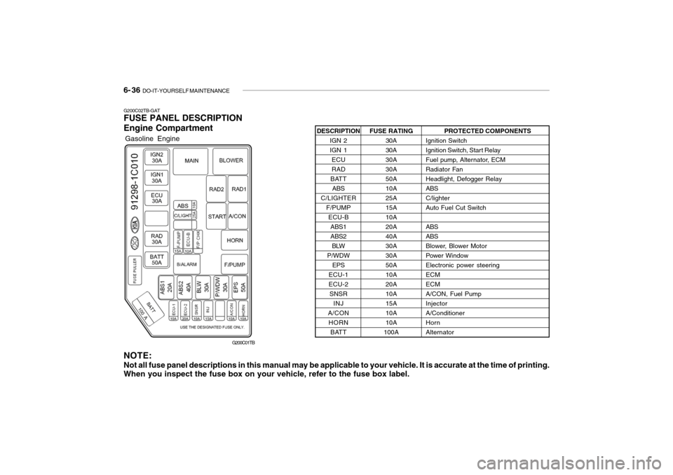
G200C02TB-GAT FUSE PANEL DESCRIPTION Engine Compartment
PROTECTED COMPONENTS
Ignition Switch
Ignition Switch, Start Relay
Fuel pump, Alternator, ECM
Radiator FanHeadlight, Defogger RelayABSC/lighterAuto Fuel Cut Switch ABS ABS
Blower, Blower Motor
Power WindowElectronic power steeringECMECMA/CON, Fuel PumpInjectorA/ConditionerHornAlternator
FUSE RATING
30A30A
30A30A50A10A25A15A10A20A40A30A30A50A10A20A10A15A10A10A
100A
DESCRIPTION
IGN 2IGN 1ECURAD
BATT ABS
C/LIGHTER F/PUMPECU-B ABS1ABS2BLW
P/WDW EPS
ECU-1ECU-2 SNSR INJ
A/CON HORN BATT
NOTE:
Not all fuse panel descriptions in this manual may be applicable to your vehicle. It is accurate at the time of printing. When you inspect the fuse box on your vehicle, refer to the fuse box label.
Gasoline Engine
G200C01TB
Page 232 of 463

DO-IT-YOURSELF MAINTENANCE 6- 37
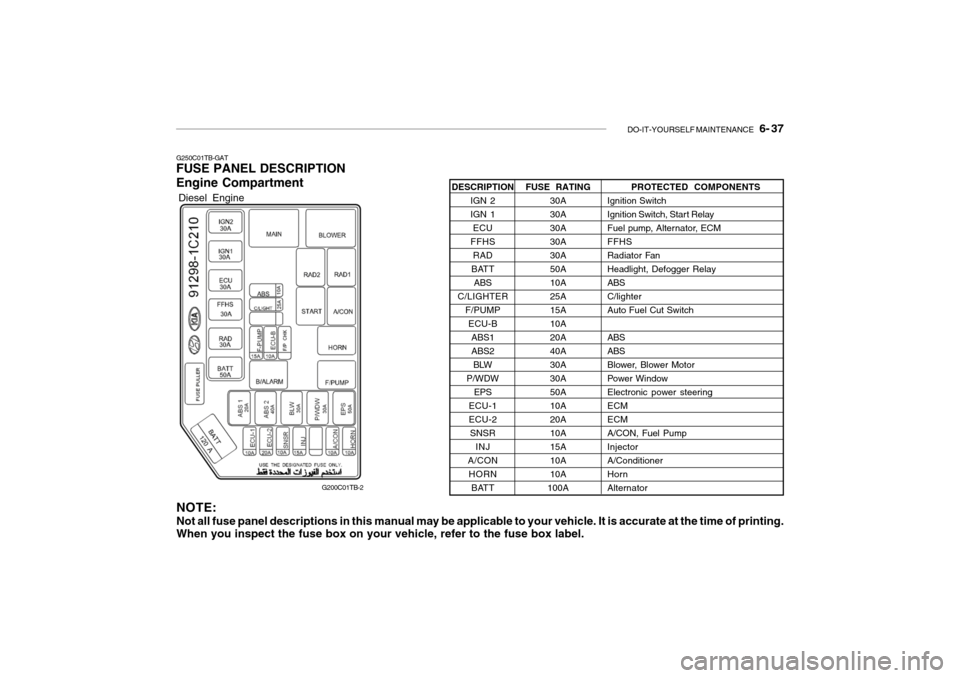
G250C01TB-GAT FUSE PANEL DESCRIPTION Engine Compartment
PROTECTED COMPONENTS
Ignition Switch
Ignition Switch, Start Relay
Fuel pump, Alternator, ECMFFHS
Radiator FanHeadlight, Defogger RelayABSC/lighterAuto Fuel Cut Switch ABS ABS
Blower, Blower Motor
Power WindowElectronic power steeringECMECMA/CON, Fuel PumpInjectorA/ConditionerHornAlternator
FUSE RATING
30A30A30A30A30A50A10A25A15A10A20A40A30A30A50A10A20A10A15A10A10A
100A
DESCRIPTION
IGN 2IGN 1ECU
FFHS RAD
BATT ABS
C/LIGHTER F/PUMPECU-BABS1ABS2BLW
P/WDW EPS
ECU-1ECU-2 SNSR INJ
A/CON HORN BATT
NOTE: Not all fuse panel descriptions in this manual may be applicable to your vehicle. It is accurate at the time of printing. When you inspect the fuse box on your vehicle, refer to the fuse box label.
Diesel Engine
G200C01TB-2
Page 252 of 463

10- 4 INDEX
H Hazard Warning System ............................................. 1-64
Headlight Aiming Adjustm ent ...................................... 6-31
Headlight Leveling Device S ystem .............................1-68
Headlight flasher ......................................................... 1-60
Headlight switch ......................................................... 1-59
Heating and cooling control ........................................ 1-86
Heating and Ventilation ............................................... 1-87
Air flow control ......................................................... 1-88
Air intake control ..................................................... 1-88
Bi-level heating ........................................................ 1-91
Fan speed control .................................................... 1-87
Temperature control ................................................. 1-90
High-Mounted Rear Stop Light.................................... 1-76
Hood Release ............................................................. 1-77
How to use luggage room ........................................... 1-80
Horn ............................................................................ 1-84
IIgnition Switch ............................................................. 2-3
Immobilizer System ..................................................... 1-5
Instrument Cluster and Indicator light ......................... 1-46
IInterior Light Interior light .............................................................. 1-72
Map light .................................................................. 1-71
Intermittent Wiper ....................................................... 1-63
JJump Starting .............................................................. 3-3 K
Key .............................................................................. 1-4
If you lose your keys .............................................. 3-14
Positions ................................................................... 2-4
Keyless entry system ................................................. 1-11
LLane change si gnal ..................................................... 1-59
Lubrication Chart .......................................................... 9-4
Luggage Net ............................................................... 1-81
Luggage Board ............................................................ 1-81
Luggage Under Tray ................................................... 1-80
Lumbar Support Control .............................................. 1-16
MMaintenance Intervals Explanation of scheduled maintenance items................................................................................. 5-8
Maintenance under severe usage conditions ............ 5-7
Scheduled maintenance ............................................ 5-4
Service requirements ................................................ 5-2
Mirrors
Day-night inside rearview ......... ................................1-75
Outside rearview mirror heater .................................1-75
O
Odometer .................................................................... 1-56
Outside rear view mirror ............................................. 1-73
Electric type ............................................................ 1-74
Manual type ............................................................. 1-73
Page 265 of 463

YOUR VEHICLE AT A GLANCE
F9
1. Glove Box
2. Passenger's Airbag
3. Hazard Warning Light
4. Digital Clock
5. Windshield Wiper/Washer Switch
6. Horn and Driver's Airbag
7. Instrument Cluster
8. Multi-Function Light Switch
9. Headlight Leveling Switch (Not all models)
10. Rear Drink Holder
CAUTION:
When installing a container of liquid air freshener inside a vehicle, do not place it near the instrumentcluster nor on the instrument panel pad surface. If there is any leakage from the air freshener onto these areas (instrument cluster, instrument panel pad or air ventilator), it may damage these parts. If the liquid from the air freshener does leak onto these areas, wash them with water immediately. 11. Parking Brake Lever
12. Shift Lever (Not all models)
13. Front Drink Holder
14. Ashtray
15. Cigar Lighter
16. Heating/Air Conditioning Control Panel
(Not all models)
17. Audio Remote Control Switch (Not all models)
18. Fuse Box
19. Hood Release Lever
!
Page 270 of 463

1- 4 FEATURES OF YOUR HYUNDAI
5) Avoid rapid acceleration and maxi-
mum throttle openings.
6) Avoid harsh braking during the first 100 miles of urban motoring or 1,000 miles of motorway driving to allow the friction facings of the brake padsand shoes to bed against the discs and drums properly.
7) No trailer towing should be under- taken during the running-in period.
B020B01FC-EAT (Diesel Engine) The longevity and performance of the vehicle are greatly affected by the care exercised during the first 1,000 miles ofmotoring. Because of modern manu- facturing techniques, rigid guidelines regarding maximum road speeds havebecome unnecessary. However, cer- tain precautions should be observed in order to obtain the best possible perfor-mance and useful life from the vehicle.
YB020A1-E BEFORE ENTERING THE VEHICLE
o Ensure that all windows, mirrors and
lamps are clean.
o Check condition of all tyres.
o Ensure that no fluid leaks are evi- dent.
o Ensure that the area around the ve- hicle is clear before driving off.
YB020B1-E AFTER ENTERING THE VEHICLE
o Ensure that all occupants fasten and correctly adjust seat belts.
o Ensure that seat and head restraint positions are adjusted for optimum safety, control and comfort.
o Adjust interior and exterior rear view mirrors.
o Verify correct operation of lamps,
horn and other electrical equipment.
o Ensure that warning lamps illumi- nate when ignition is turned on.
NOTE: Fluid levels such as engine oil, en- gine coolant, brake and windscreen washer fluid should be checked dailyor at each refuelling, whichever oc- curs sooner. B020A01FC-EAT RUNNING IN YOUR NEW HYUNDAI (Petrol Engine) The longevity and performance of the vehicle are greatly affected by the care exercised during the first 1,000 miles ofmotoring. Because of modern manu- facturing techniques, rigid guidelines regarding maximum road speeds havebecome unnecessary. However, cer- tain precautions should be observed in order to obtain the best possible perfor-mance and useful life from the vehicle.
1) Do not race the engine without a load
(i.e revving the engine in neutral).
2) During the first 500 miles the maxi-
mum engine speed should be re- stricted to 3,000 rpm and gradually increased thereafter.
3) Avoid prolonged constant speed op- eration. The internal components ofthe engine will become more quickly run in if the operation speed is variedduring the running-in period.
4) Never allow the engine to labour. Use
the gearbox freely and avoid largethrottle openings when the engine speed is below 1,500 rpm.