weight Hyundai Grandeur 2003 Owner's Manual
[x] Cancel search | Manufacturer: HYUNDAI, Model Year: 2003, Model line: Grandeur, Model: Hyundai Grandeur 2003Pages: 235, PDF Size: 14.25 MB
Page 26 of 235
1- 12 FEATURES OF YOUR HYUNDAI
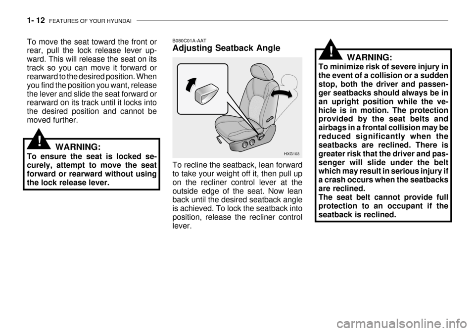
To move the seat toward the front or rear, pull the lock release lever up- ward. This will release the seat on itstrack so you can move it forward or rearward to the desired position. When you find the position you want, releasethe lever and slide the seat forward or rearward on its track until it locks into the desired position and cannot bemoved further.
HXG103
B080C01A-AAT Adjusting Seatback Angle
To recline the seatback, lean forward to take your weight off it, then pull up on the recliner control lever at theoutside edge of the seat. Now lean back until the desired seatback angle is achieved. To lock the seatback intoposition, release the recliner control lever. WARNING:
To minimize risk of severe injury in the event of a collision or a suddenstop, both the driver and passen- ger seatbacks should always be in an upright position while the ve-hicle is in motion. The protection provided by the seat belts and airbags in a frontal collision may bereduced significantly when the seatbacks are reclined. There is greater risk that the driver and pas-senger will slide under the belt which may result in serious injury if a crash occurs when the seatbacksare reclined. The seat belt cannot provide full protection to an occupant if theseatback is reclined.
!
WARNING:
To ensure the seat is locked se- curely, attempt to move the seat forward or rearward without usingthe lock release lever.!
Page 50 of 235
1- 36 FEATURES OF YOUR HYUNDAI
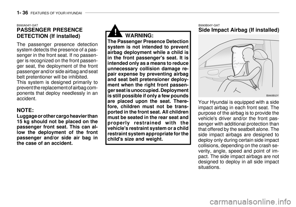
B990B04Y-GAT Side Impact Airbag (If installed)
Your Hyundai is equipped with a side impact airbag in each front seat. The purpose of the airbag is to provide the vehicle's driver and/or the front pas-senger with additional protection than that offered by the seatbelt alone. The side impact airbags are designed todeploy only during certain side impact collisions, depending on the crash se- verity, angle, speed and point of im-pact. The side impact airbags are not designed to deploy in all side impact situations. B990B02Y
WARNING:
The Passenger Presence Detectionsystem is not intended to preventairbag deployment while a child is in the front passenger's seat. It is intended only as a means to reduceunnecessary collision damage re- pair expense by preventing airbag and seat belt pretensioner deploy-ment when the right front passen- ger seat is unoccupied. Deployment is still possible if only a few poundsare placed upon the seat. There- fore, children must not be trans- ported in the front seat. All childrenmust be seated in the rear seat and properly restrained with the vehicle's restraint system or a childrestraint system appropriate for the child's size and weight.
!
B990A04Y-GAT PASSENGER PRESENCE
DETECTION (If installed) The passenger presence detection system detects the presence of a pas- senger in the front seat. If no passen-ger is recognized on the front passen- ger seat, the deployment of the front passenger and/or side airbag and seatbelt pretentioner will be inhibited. This system is designed primarily to prevent the replacement of airbag com-ponents that deploy needlessly in an accident. NOTE: Luggage or other cargo heavier than 15 kg should not be placed on the passenger front seat. This can al- low the deployment of the frontpassenger and/or side air bag in the case of an accident.
Page 87 of 235
FEATURES OF YOUR HYUNDAI 1- 73
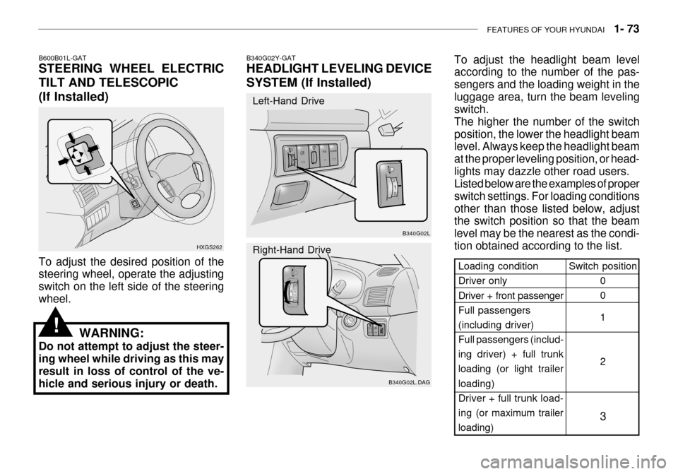
B600B01L-GAT STEERING WHEEL ELECTRIC TILT AND TELESCOPIC
(If Installed)
HXGS262
To adjust the desired position of the steering wheel, operate the adjusting switch on the left side of the steeringwheel.
WARNING:
Do not attempt to adjust the steer-ing wheel while driving as this mayresult in loss of control of the ve- hicle and serious injury or death.
!
Switch position
0 0 1 2
3Loading condition Driver only Driver + front passenger Full passengers(including driver) Full passengers (includ- ing driver) + full trunkloading (or light trailer loading)
Driver + full trunk load-ing (or maximum trailer
loading)
B340G02L
B340G02L.DAG
B340G02Y-GAT HEADLIGHT LEVELING DEVICE
SYSTEM (If Installed)
Left-Hand Drive Right-Hand Drive
To adjust the headlight beam level according to the number of the pas- sengers and the loading weight in theluggage area, turn the beam leveling switch. The higher the number of the switchposition, the lower the headlight beam level. Always keep the headlight beam at the proper leveling position, or head-lights may dazzle other road users. Listed below are the examples of proper switch settings. For loading conditionsother than those listed below, adjust the switch position so that the beam level may be the nearest as the condi-tion obtained according to the list.
Page 147 of 235

DRIVING YOUR HYUNDAI 2- 15
C150A01A-AAT SMOOTH CORNERING Avoid braking or gear changing in cor- ners, especially when roads are wet. Ideally, corners should always be takenunder gentle acceleration. If you follow these suggestions, tire wear will be held to a minimum.
o Don't "ride" the brake or clutch pedal.
This can increase fuel consumptionand also increase wear on thesecomponents. In addition, driving with your foot resting on the brake pedal may cause the brakes to overheat,which reduces their effectiveness and may lead to more serious con- sequences.
o Take care of your tires. Keep them inflated to the recommended pres-sure. Incorrect inflation, either toomuch or too little, results in unnec- essary tire wear. Check the tire pres- sures at least once a month.
o Be sure that the wheels are aligned correctly. Improper alignment canresult from hitting curbs or drivingtoo fast over irregular surfaces. Poor alignment causes faster tire wear and may also result in other prob-lems as well as greater fuel con- sumption.
o Keep your car in good condition. For better fuel economy and reducedmaintenance costs, maintain your car in accordance with the mainte-nance schedule in Section 5. If you drive your car in severe conditions, more frequent maintenance is re-quired (see Section 5 for details). o Keep your car clean. For maximum
service, your Hyundai should bekept clean and free of corrosivematerials. It is especially important that mud, dirt, ice, etc. not be al- lowed to accumulate on the under-side of the car. This extra weight can result in increased fuel con- sumption and also contribute to cor-rosion.
o Travel lightly. Don't carry unneces-
sary weight in your car. Weight re-duces fuel economy.
o Don't let the engine idle longer than
necessary. If you are waiting (andnot in traffic), turn off your engine and restart only when you're ready to go.
o Remember, your Hyundai does not require extended warm-up. As soonas the engine is running smoothly,you can drive away. In very cold weather, however, give your engine a slightly longer warm-up period. o Don't "lug" or "over-rev" the engine.
Lugging is driving too slowly in toohigh a gear resulting in the enginebucking. If this happens, shift to a lower gear. Over-revving is racing the engine beyond its safe limit.This can be avoided by shifting at the recommended speeds.
o Use your air conditioning sparingly. The air conditioning system is oper-ated by engine power so your fuel economy is reduced when you useit.
Page 148 of 235

2- 16 DRIVING YOUR HYUNDAI
C160F01A-AAT Check Spark Plugs and Ignition System Inspect your spark plugs as described in Section 6 and replace them if neces-sary. Also check all ignition wiring and components to be sure they are not cracked, worn or damaged in any way.
C160C01A-AAT Use High Quality Ethylene Glycol Coolant Your Hyundai is delivered with high quality ethylene glycol coolant in the cooling system. It is the only type of coolant that should be used because ithelps prevent corrosion in the cooling system, lubricates the water pump and prevents freezing. Be sure to replaceor replenish your coolant in accor- dance with the maintenance schedule in Section 5. Before winter, have yourcoolant tested to assure that its freez- ing point is sufficient for the tempera- tures anticipated during the winter. C160D01A-AAT Check Battery and Cables Winter puts additional burdens on the battery system. Visually inspect thebattery and cables as described in Section 6. The level of charge in your battery can be checked by your Hyun-dai dealer or a service station. C160E01A-AAT Change to "Winter Weight" Oil if Necessary In some climates it is recommended that a lower viscosity "winter weight" oil be used during cold weather. SeeSection 9 for recommendations. If you aren't sure what weight oil you should use, consult your Hyundai dealer.
C160A01A-AAT WINTER DRIVING The more severe weather conditions of winter result in greater wear andother problems. To minimize the prob- lems of winter driving, you should fol- low these suggestions: C160B01A-GAT Snowy or Icy Conditions To drive your vehicle in deep snow, it may be necessary to use snow tires or to install tire chains on your tires. If snow tires are needed, it is necessaryto select tires equivalent in size and type of the original equipment tires. Failure to do so may adversely affectthe safety and handling of your car. Furthermore, speeding, rapid accel- eration, sudden brake applications, andsharp turns are potentially very haz- ardous practices. During deceleration, use engine brak-ing to the fullest extent. Sudden brake applications on snowy or icy roads may cause skids to occur. You need tokeep sufficient distance between the vehicle in front and your vehicle. Also, apply the brake gently. It should be noted that installing tire chains on the tire will provide a greater driving force, but will not prevent side skids. NOTE: Tire chains are not legal in all prov- inces. Check province laws beforefitting tire chains.
Page 151 of 235
DRIVING YOUR HYUNDAI 2- 19
C190C01Y-GAT Trailer Brakes If your trailer is equipped with a braking system, make sure it conforms to fed-eral and/or local regulations and that it is properly installed and operating cor- rectly. NOTE: If you tow a trailer or vehicle, your
car will require more frequent main- tenance due to the additional load.See "Maintenance Under Severe Usage Conditions" on page 5-6.
CAUTION:
o Never connect a trailer brake sys- tem directly to the vehicle brake system.
o When towing a trailer on steep
grades (in excess of 12%) pay
close attention to the engine cool- ant temperature gauge to ensure the engine does not overheat. Ifthe needle of the coolant tem-
perature gauge moves across the dial towards "H" (HOT), pull overand stop as soon as it is safe to
!
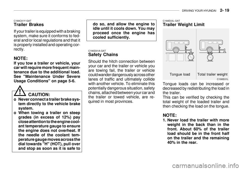
C190E03L-GAT Trailer Weight Limit
Tongue load Total trailer weight C190E01L
C190D01A-GAT Safety Chains Should the hitch connection between your car and the trailer or vehicle youare towing fail, the trailer or vehicle could wander dangerously across other lanes of traffic and ultimately collidewith another vehicle. To eliminate this potentially dangerous situation, safety chains, attached between your car and the trailer or towed vehicle, are re- quired in most provinces.
Tongue loads can be increased ordecreased by redistributing the load inthe trailer. This can be verified by checking the total weight of the loaded trailer andthen checking the load on the tongue. NOTE:
1. Never load the trailer with more
weight in the back than in the front. About 60% of the trailer load should be in the front half on the trailer and the remaining40% in the rear.
do so, and allow the engine to idle until it cools down. You may proceed once the engine hascooled sufficiently.
Page 152 of 235
2- 20 DRIVING YOUR HYUNDAI
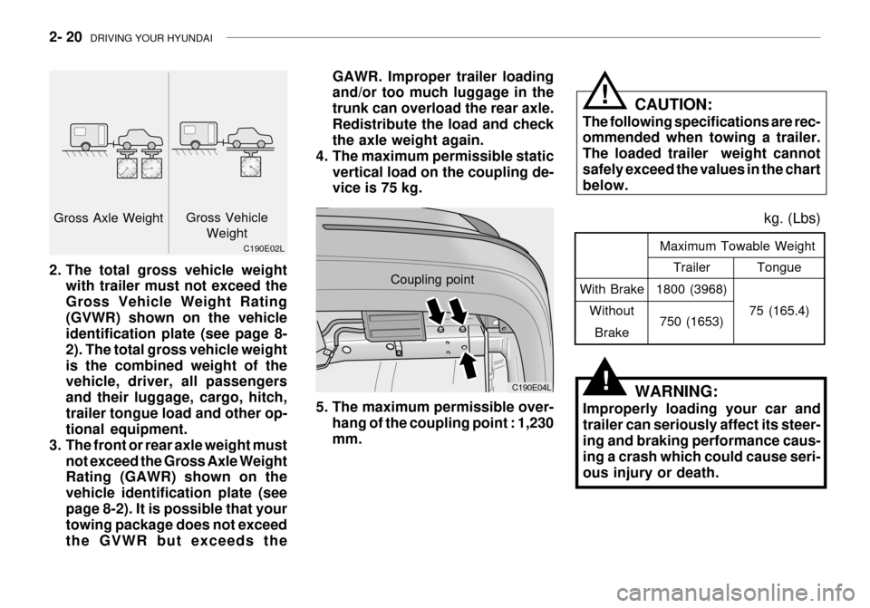
With Brake
WithoutBrake Tongue
75 (165.4)
Maximum Towable Weight
kg. (Lbs)
Trailer
1800 (3968)
750 (1653)
WARNING:
Improperly loading your car and trailer can seriously affect its steer- ing and braking performance caus- ing a crash which could cause seri-ous injury or death.
Coupling point
C190E04L
GAWR. Improper trailer loading and/or too much luggage in the trunk can overload the rear axle.Redistribute the load and check the axle weight again.
4. The maximum permissible static vertical load on the coupling de-vice is 75 kg. CAUTION:
The following specifications are rec-ommended when towing a trailer. The loaded trailer weight cannotsafely exceed the values in the chart below.
!
!
5. The maximum permissible over- hang of the coupling point : 1,230 mm.
2. The total gross vehicle weight
with trailer must not exceed theGross Vehicle Weight Rating(GVWR) shown on the vehicle identification plate (see page 8- 2). The total gross vehicle weightis the combined weight of the vehicle, driver, all passengers and their luggage, cargo, hitch,trailer tongue load and other op- tional equipment.
3. The front or rear axle weight must
not exceed the Gross Axle WeightRating (GAWR) shown on the vehicle identification plate (seepage 8-2). It is possible that your towing package does not exceed the GVWR but exceeds the
C190E02L
Gross Axle Weight
Gross Vehicle
Weight
Page 206 of 235
DO-IT-YOURSELF MAINTENANCE 6- 25
Before performing aiming adjustment,
make sure of the following.
1. Keep all tires inflated to the correct
pressure.
2. Place the vehicle on level ground
and press the front bumper & rear bumper down several times. Place the vehicle at a distance of 3 m (118 in.) from the test wall.
3. See that the vehicle is unloaded (except for full levels of coolant,engine oil and fuel, and spare tire,jack, and tools). Have the driver or equivalent weight placed in driver's seat.
4. Clean the head light lenses and
turn on the headlights (low beam).
5. Open the hood.
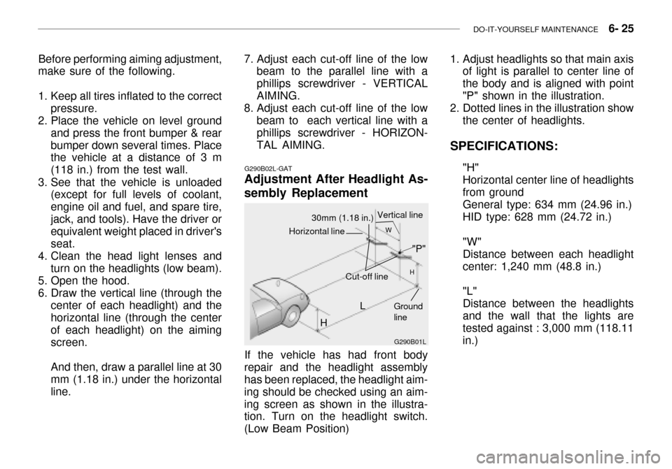
6. Draw the vertical line (through the center of each headlight) and the horizontal line (through the center of each headlight) on the aimingscreen. And then, draw a parallel line at 30 mm (1.18 in.) under the horizontal line.
G290B02L-GAT
Adjustment After Headlight As- sembly Replacement
G290B01L
LW
H
H Cut-off line
Ground line
If the vehicle has had front body
repair and the headlight assembly has been replaced, the headlight aim- ing should be checked using an aim-ing screen as shown in the illustra- tion. Turn on the headlight switch. (Low Beam Position)
"P"
Horizontal line
30mm (1.18 in.) Vertical line
7. Adjust each cut-off line of the low
beam to the parallel line with a phillips screwdriver - VERTICALAIMING.
8. Adjust each cut-off line of the low
beam to each vertical line with a phillips screwdriver - HORIZON- TAL AIMING. 1. Adjust headlights so that main axis
of light is parallel to center line ofthe body and is aligned with point"P" shown in the illustration.
2. Dotted lines in the illustration show the center of headlights.
SPECIFICATIONS: "H"Horizontal center line of headlightsfrom groundGeneral type: 634 mm (24.96 in.) HID type: 628 mm (24.72 in.) "W" Distance between each headlightcenter: 1,240 mm (48.8 in.) "L" Distance between the headlightsand the wall that the lights aretested against : 3,000 mm (118.11 in.)