Hyundai H-1 (Grand Starex) 2005 Owner's Manual
Manufacturer: HYUNDAI, Model Year: 2005, Model line: H-1 (Grand Starex), Model: Hyundai H-1 (Grand Starex) 2005Pages: 205, PDF Size: 9.14 MB
Page 101 of 205
3
STARTING AND OPERATING
33
!
The following procedures can be used to confirm that the limited-slip differen-tial is functioning properly:
(1) Position the vehicle so that one
wheel is on a dry paved surface and the other on ice, snow, mud, etc. Drive the vehicle, and observe theoperation of the limited-slip differ- ential. The vehicle should not becomestuck if the differential is function- ing properly.
(2) Depress the accelerator pedal gradually, and then when traction isgood, depress it forcefully. If the vehicle accelerates well, the differ-ential is functioning properly. CAUTION:
o Never start the engine while one of the rear wheels is jacked up and the other in contact with the ground; doing so may cause thevehicle to jump forward.
o If one of the rear wheels begins
to spin in mud, snow, etc., thevehicle can sometimes be driven out by depressing the accelera- tor pedal further; however, avoidrunning the engine continuously at high rpm because doing so could damage the limited-slipdifferential.
Page 102 of 205
4
Tools and Jack ............................................................. 4-2
Spare Tire ..................................................................... 4-3
If You Have a Flat Tire ................................................. 4-6
Changing a Flat Tire ..................................................... 4-7Towing........................................................................ 4-13
Bleeding the Fuel System .......................................... 4-18
Removal of Water from the Fuel Filter ....................... 4-19
If the Engine Will Not Start ......................................... 4-20
Jump Starting ............................................................. 4-21
If the Engine Overheats ............................................. 4-22
Checking and Replacing Fuses ................................. 4-24
Headlight Aiming Adjustment ..................................... 4-26
Replacement of Light Bulbs ....................................... 4-27
Bulb Wattage .............................................................. 4-35
Fuse Panel Description .............................................. 4-37
IN CASE OF EMERGENCY
4
Page 103 of 205
44IN CASE OF EMERGENCY
2
Release valve
TOOLS AND JACK
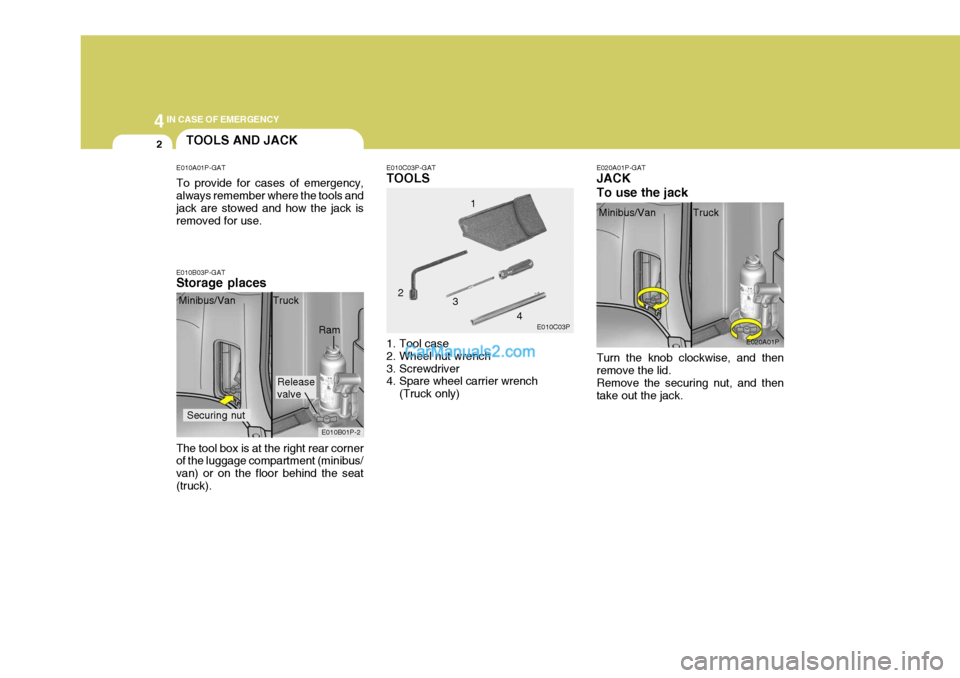
E010A01P-GAT To provide for cases of emergency, always remember where the tools and jack are stowed and how the jack is removed for use.
E010B03P-GAT Storage places E010C03P-GAT TOOLS
E020A01P-GATJACK To use the jack
The tool box is at the right rear corner of the luggage compartment (minibus/ van) or on the floor behind the seat(truck). Minibus/Van Truck
1. Tool case
2. Wheel nut wrench
3. Screwdriver
4. Spare wheel carrier wrench(Truck only) 4
Turn the knob clockwise, and then remove the lid. Remove the securing nut, and then take out the jack.
E010B01P-2 E010C03P
E020A01P
Minibus/Van Truck
Securing nut
Ram 1
2 3
Page 104 of 205
4
CORROSION PREVENTION AND APPEARANCE CARE
3
4
IN CASE OF EMERGENCY
3
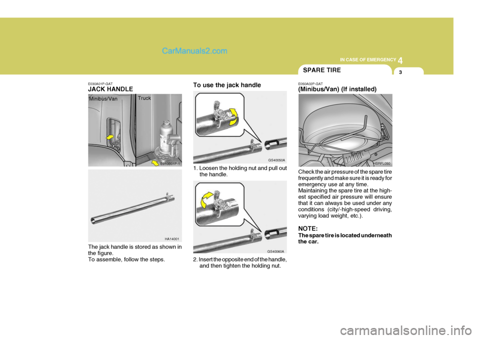
E030A01P-GAT JACK HANDLE
1. Loosen the holding nut and pull outthe handle.
The jack handle is stored as shown in the figure. To assemble, follow the steps. 2. Insert the opposite end of the handle,
and then tighten the holding nut.
E010B01P-1
HA14001 GS40050A
GS40060A
SPARE TIRE
E050A02P-GAT (Minibus/Van) (If installed) Check the air pressure of the spare tire frequently and make sure it is ready foremergency use at any time. Maintaining the spare tire at the high- est specified air pressure will ensurethat it can always be used under any conditions (city/-high-speed driving, varying load weight, etc.). NOTE: The spare tire is located underneath the car. HSRFL050
Minibus/Van
Truck To use the jack handle
Page 105 of 205
44IN CASE OF EMERGENCY
4
E050B02P-GAT To reinstall the spare tire Installation is the reverse order of dis- assembly.
CAUTION:
The spare tire should always besecurely in position.If a flat tire is changed, put the flat tire in the spare tire mounting posi- tion, and use the wheel nut wrenchto secure it firmly.
!
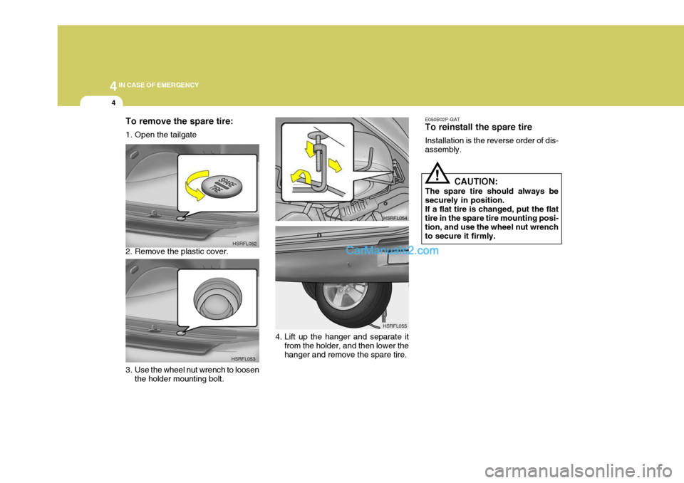
To remove the spare tire:
1. Open the tailgate
2. Remove the plastic cover.
HSRFL052
HSRFL053
3. Use the wheel nut wrench to loosen the holder mounting bolt. HSRFL054
HSRFL055
4. Lift up the hanger and separate it from the holder, and then lower the hanger and remove the spare tire.
Page 106 of 205
4
CORROSION PREVENTION AND APPEARANCE CARE
5
4
IN CASE OF EMERGENCY
5
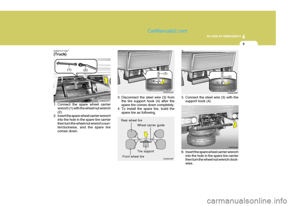
E050C01P-GAT (Truck)
1. Connect the spare wheel carrier
wrench (1) with the wheel nut wrench (2).
2. Insert the spare wheel carrier wrench
into the hole in the spare tire carrierthen turn the wheel nut wrench coun- terclockwise, and the spare tire comes down. 3. Disconnect the steel wire (3) from
the tire support hook (4) after thespare tire comes down completely.
4. To install the spare tire, build the spare tire as following.
E050C01P
E050C02P
5. Connect the steel wire (3) with thesupport hook (4).
6. Insert the spare wheel carrier wrench into the hole in the spare tire carrier then turn the wheel nut wrench clock- wise. HHR4026
E050C03P E050C05P
Rear wheel tire
Wheel carrier guide
Front wheel tire Tire support
(1)
(2)
(3)
(4)
(3)
(4)
Page 107 of 205
44IN CASE OF EMERGENCY
6IF YOU HAVE A FLAT TIRE
7. After the spare tire fully raised, tighten by hand to about 30 kg .
f
(295 N). Then, remove the spare tire carrier wrench with care not to turn it in thereverse direction. Now, ensure that the tire is secured in position.
CAUTION:
If you cannot secure the spare tire in position, load it on the cargodeck and ask your nearest service shop for inspection.
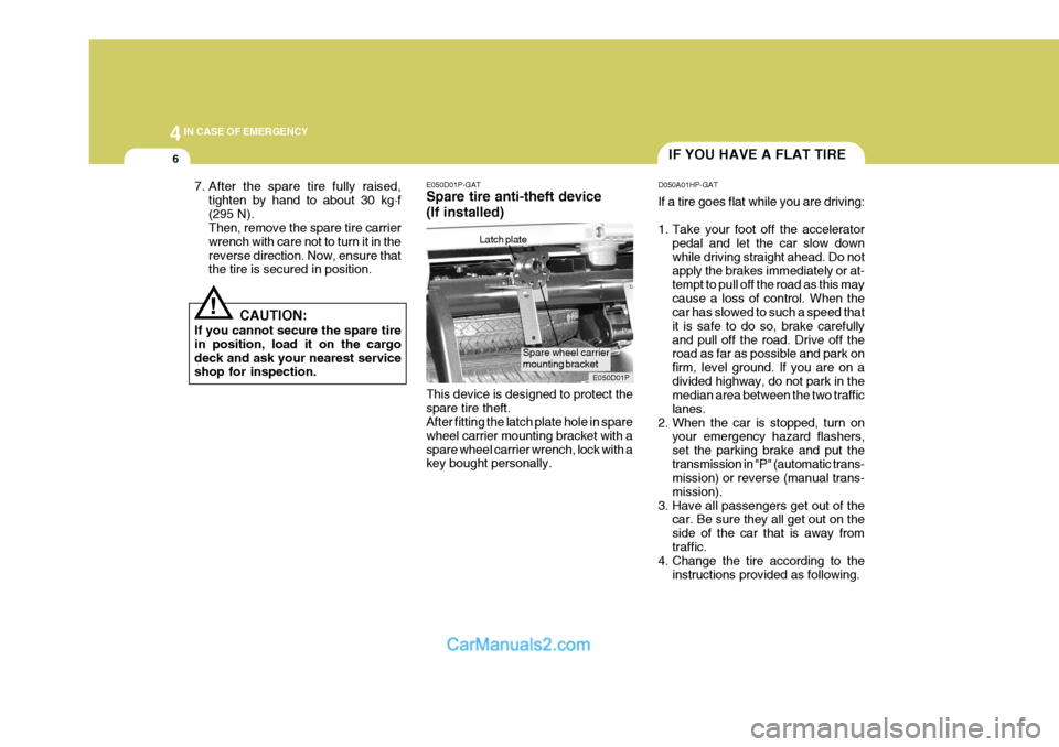
! E050D01P-GAT Spare tire anti-theft device (If installed) This device is designed to protect the spare tire theft. After fitting the latch plate hole in spare wheel carrier mounting bracket with aspare wheel carrier wrench, lock with a key bought personally.Latch plate
E050D01PD050A01HP-GAT If a tire goes flat while you are driving:
1. Take your foot off the accelerator
pedal and let the car slow down while driving straight ahead. Do not apply the brakes immediately or at- tempt to pull off the road as this maycause a loss of control. When the car has slowed to such a speed that it is safe to do so, brake carefullyand pull off the road. Drive off the road as far as possible and park on firm, level ground. If you are on adivided highway, do not park in the median area between the two traffic lanes.
2. When the car is stopped, turn on your emergency hazard flashers,set the parking brake and put thetransmission in "P" (automatic trans- mission) or reverse (manual trans- mission).
3. Have all passengers get out of the car. Be sure they all get out on theside of the car that is away fromtraffic.
4. Change the tire according to the
instructions provided as following.
Spare wheel carrier mounting bracket
Page 108 of 205
4
CORROSION PREVENTION AND APPEARANCE CARE
7
4
IN CASE OF EMERGENCY
7CHANGING A FLAT TIRE
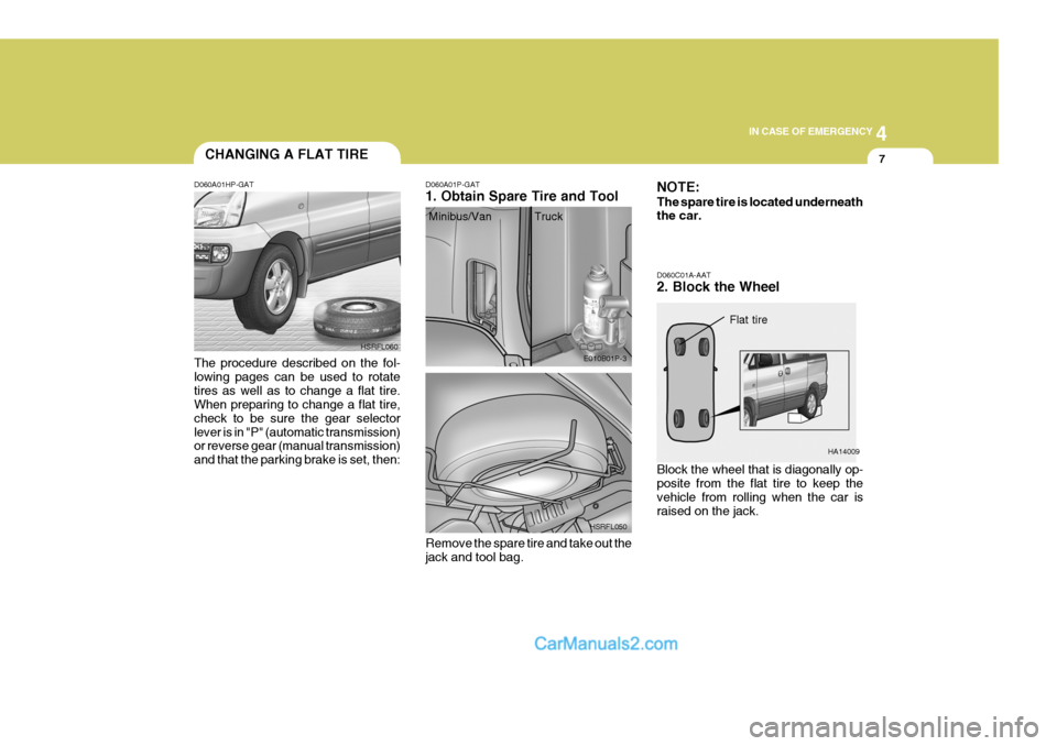
D060A01HP-GAT The procedure described on the fol- lowing pages can be used to rotatetires as well as to change a flat tire. When preparing to change a flat tire, check to be sure the gear selectorlever is in "P" (automatic transmission) or reverse gear (manual transmission) and that the parking brake is set, then: HSRFL060D060A01P-GAT 1. Obtain Spare Tire and Tool
E010B01P-3
HSRFL050
Remove the spare tire and take out the jack and tool bag. D060C01A-AAT 2. Block the Wheel Block the wheel that is diagonally op- posite from the flat tire to keep the vehicle from rolling when the car israised on the jack.
HA14009
NOTE: The spare tire is located underneath the car.
Flat tire
Minibus/Van Truck
Page 109 of 205
44IN CASE OF EMERGENCY
8
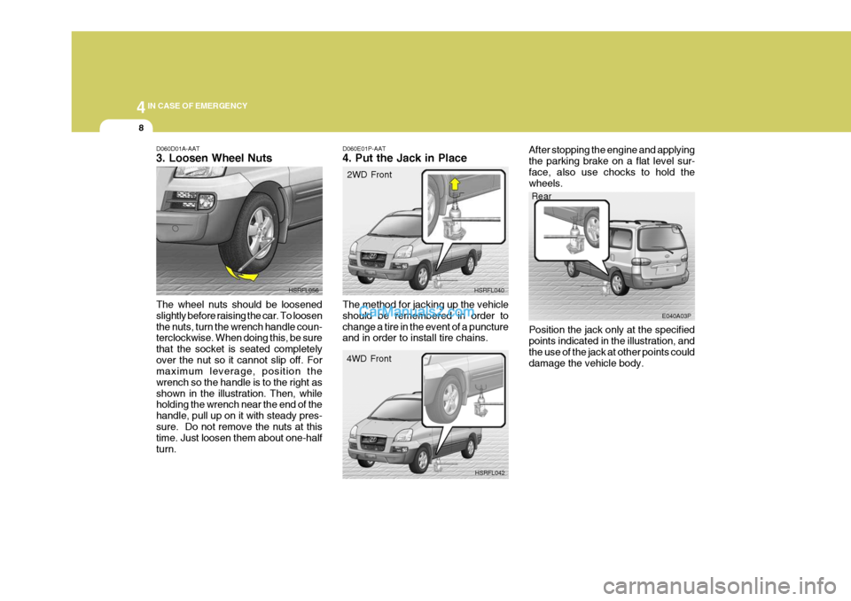
D060D01A-AAT 3. Loosen Wheel Nuts The wheel nuts should be loosened slightly before raising the car. To loosenthe nuts, turn the wrench handle coun- terclockwise. When doing this, be sure that the socket is seated completelyover the nut so it cannot slip off. For maximum leverage, position the wrench so the handle is to the right asshown in the illustration. Then, while holding the wrench near the end of the handle, pull up on it with steady pres-sure. Do not remove the nuts at this time. Just loosen them about one-half turn. HSRFL056
D060E01P-AAT 4. Put the Jack in Place
Rear
E040A03P
HSRFL040
HSRFL042
2WD Front
4WD Front
The method for jacking up the vehicle should be remembered in order tochange a tire in the event of a puncture and in order to install tire chains. After stopping the engine and applying the parking brake on a flat level sur-face, also use chocks to hold the wheels. Position the jack only at the specified points indicated in the illustration, and the use of the jack at other points coulddamage the vehicle body.
Page 110 of 205
4
CORROSION PREVENTION AND APPEARANCE CARE
9
4
IN CASE OF EMERGENCY
9
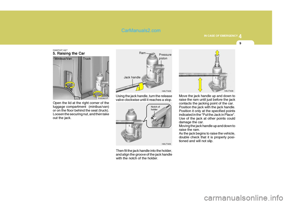
D060F02P-GAT 5. Raising the Car Open the lid at the right corner of the luggage compartment (minibus/van)or on the floor behind the seat (truck). Loosen the securing nut, and then take out the jack. Using the jack handle, turn the releasevalve clockwise until it reaches a stop.
HAUT408
HAUT405
E020A01P
Move the jack handle up and down to raise the ram until just before the jack contacts the jacking point of the car.Position the jack with the jack handle. Position it only at the specified points indicated in the "Put the Jack in Place".Use of the jack at other points could damage the car. Moving the jack handle up and down toraise the ram. As the jack begins to raise the vehicle, double check that it is properly posi-tioned and will not slip.
Then fit the jack handle into the holder,and align the groove of the jack handle with the notch of the holder.
Minibus/Van Truck
HAUT406RamPressure piston
Jack handle
Notch of holder