Hyundai H-1 (Grand Starex) 2006 Owner's Manual
Manufacturer: HYUNDAI, Model Year: 2006, Model line: H-1 (Grand Starex), Model: Hyundai H-1 (Grand Starex) 2006Pages: 284, PDF Size: 12.21 MB
Page 241 of 284
6
VEHICLE MAINTENANCE REQUIREMENTS
13
G080E01P-GAT
o Vacuum and Crankcase
Ventilation Hoses
Inspect the surface of hoses for evi- dence of heat and/or mechanical dam- age. Hard and brittle rubber, cracking, tears, cuts, abrasions, and excessiveswelling indicate deterioration. Particu- lar attention should be paid to examin- ing those hose surfaces nearest tohigh heat sources, such as the ex- haust manifold. Inspect the hose routing to assure that the hoses do not come in contact with any heat source, sharp edges or mov- ing component which might cause heatdamage or mechanical wear. Inspect all hose connections, such as clamps and couplings, to make sure they aresecure, and that no leaks are present. Hoses should be replaced immedi- ately if there is any evidence of dete-rioration or damage. G080F01P-GAT
o Fuel Hose, Vapor Hose and
Fuel Filler Cap
The fuel hose, vapor hose and fuelfiller cap should be inspected at those intervals specified in the maintenance schedule. Make sure that a new fuelhose, vapor hose or fuel filler cap is correctly replaced. Consult your Hyundai dealer if you have any ques-tions. G080G01P-GAT
o Air Cleaner Filter
A genuine Hyundai part is recom- mended for replacement of the air cleaner filter. G080H01P-GAT
o Spark Plugs (Gasoline) Make sure to install new spark plugs of the correct heat range. G080I01P-GAT
o Drive Belts Inspect all drive belts (water pump and alternator) for evidence of cuts, cracks, excessive wear or oiliness, and re- place if necessary. Drive belts shouldbe checked periodically for proper ten- sion and adjusted as necessary. G080J01P-GAT
o Engine Coolant The coolant should be changed at those intervals specified in the Vehicle Maintenance Requirements Section. G080K01P-GAT
o Timing Belt Inspect all parts related with the timing belt for damage and deformation. Re-place any damaged parts.
Page 242 of 284
6VEHICLE MAINTENANCE REQUIREMENTS
14
G080N01P-GAT
o Brake Hoses and Lines
Visually check for proper installation,
chafing, cracks, deterioration and any leakage. Replace any deteriorated or damaged parts immediately.
G080O01P-GAT
o Brake Fluid
Check brake fluid level in the brake
fluid reservoir. The level should be between "MIN" and "MAX" marks on the side of the reservoir. Use onlyhydraulic brake fluid conforming SAE J1703.
G080P01P-GAT
o Rear Brake Drums and
Linings
Check for scoring, burning, leaking
fluid, broken parts, and excessive wear. G080Q01P-GAT
o Brake Pads, Calipers and
Rotors
Check the pads for excessive wear, discs for run out and wear, and cali- pers for fluid leakage. G080R01P-GAT
o Parking Brake
Inspect the parking brake system such as parking brake lever, cables, and so on. For detailed service procedures,refer to the Shop Manual.
G080S01P-GAT
o Exhaust Pipe Connections,
Muffler and Suspension Bolts
Check the exhaust pipe, muffler, and
suspension connections for loosenessor damage.
G080L01P-GAT
o Manual Transmission Oil Check manual transmission oil ac- cording to the maintenance schedule. NOTE: If the oil level is low, check for possible leaks before adding oil. Do not overfill. G080M03P-GAT
o Automatic Transmission Fluid The fluid level should be in the "HOT" range of the dipstick, after engine and transmission are at normal operatingtemperature. Check the Automatic Transmission Fluid level with the en- gine running and the transmission inneutral, with the parking brake properly applied. Use MOBIL DEXRON-II or DIAMOND ATF SP-I when adding orchanging fluid.
Page 243 of 284
6
VEHICLE MAINTENANCE REQUIREMENTS
15
G080T01P-GAT
o Steering Bear Box, Linkage
and Boots
With the vehicle stopped and engine off, check for excessive free-play in the steering wheel. Check the linkage for bends or damage. Check the dustboots and ball joints for deterioration, cracks, or damage. Replace any dam- aged parts. G080U01P-GAT
o Wheel Bearing Grease
Check the wheel bearings and grease according to the maintenance sched- ule. For inspection procedures, seeShop Manual.
Page 244 of 284
7
Emission Control System ............................................. 7-2
Catalytic Converter ....................................................... 7-3EMISSION CONTROL SYSTEM
7
a1ene-7.p65
5/6/2005, 10:41 AM
1
Page 245 of 284
7EMISSION CONTROL SYSTEM
2EMISSION CONTROL SYSTEM
H010A01P-GAT (Gasoline) Your Hyundai is equipped with an emission control system. There are three emission control sys- tems which are as follows.
(1) Crankcase emission control sys- tem
(2) Evaporative emission control sys- tem
(3) Exhaust emission control systemIn order to assure the proper function of the emission control systems, it is recommended that you have your vehicle inspected and maintained byan authorized Hyundai dealer in ac- cordance with the maintenance sched- ule in this manual. H020A01P-GAT
1. Crankcase Emission Control
System
The positive crankcase ventilation
system is employed to prevent airpollution caused by blow-by gases being emitted from the crankcase.This system supplies fresh air to the crankcase through the air cleaner. Inside the crankcase, the fresh airmixes with blow-by gases, then passes through the PCV valve into the induction system.
H080A01P-GAT PCV Valve The crankcase ventilation system must be kept clean to maintain good engine performance. Periodic servicing is required to re- move combustion products from the PCV valve. H030A01P-GAT
2. Evaporative Emission Control
System (except canister)
The Evaporative Emission ControlSystem is designed to prevent fuel vapors from escaping into the atmo-sphere.If the fuel-vapor vent line is cloggedor damaged, the fuel-vapor mixturewill escape into the atmosphere and cause insufficient emission control. Disconnect the line at both ends, and blow it clean with compressed air. Remove the filler cap from the filler pipe, and check to see if there is evidence that the packing contact to the filler pipe is faulty. The overfilllimiter (2-way valve) installed on the vapor line between the canister inlet and fuel tank outlet must be checkedfor correct operation.
a1ene-7.p65 5/6/2005, 10:41 AM
2
Page 246 of 284
7
EMISSION CONTROL SYSTEM
3CATALYTIC CONVERTER
H040A01P-GAT Canister While the engine is inoperative, fuel vapors generated inside the fuel tank are absorbed and stored in the canis-ter. When the engine is running, the fuel vapors absorbed in the canister are drawn into the induction systemthrough the purge control solenoid valve. H090A01P-GAT Purge Control Solenoid Valve The purge control solenoid valve is controlled by the ECU; when the en-gine coolant temperature is low, and during idling, it closes, so that evapo- rated fuel is not taken into the surgetank. After engine warm-up, during ordinary driving, it opens so as to introduce evaporated fuel to the surgetank. H050A01P-GAT
3. Exhaust Emission Control
System
The Exhaust Emission Control Sys-
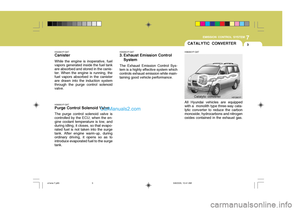
tem is a highly effective system which controls exhaust emission while main-taining good vehicle performance. H060A01P-GAT All Hyundai vehicles are equipped with a monolith type three-way cata- lytic converter to reduce the carbonmonoxide, hydrocarbons and nitrogen oxides contained in the exhaust gas.
H010A01P
Catalytic converter
a1ene-7.p65
5/6/2005, 10:41 AM
3
Page 247 of 284
Engine Compartment ................................................... 8-2
General Checks ........................................................... 8-6
Checking the Engine Oil .............................................. 8-7 Checking the Engine Coolant..................................... 8-10
Checking the Battery .................................................. 8-13
Air Conditioning Care .................................................. 8-15
Changing the Climate Control Air Filter .. ....................8-16
Checking the Brake Fluid ............................................ 8-17
Checking the Clutch Fluid ........................................... 8-18
Checking the Automatic Transmission Fluid ..............8-18
Filling the Washer Reservoir....................................... 8-20
Windshield Wiper Blades ............................................ 8-21
Tail Gate Window Washer Flui d .................................8-23
Checking the Freeplay ................................................ 8-23
Checking Drive Belts .................................................. 8-24
Parking Brake Lever Stroke ....................................... 8-25
Tire .............................................................................. 8-25
8
DO-IT YOURSELF MAINTENANCE
8
Page 248 of 284
8DO-IT YOURSELF MAINTENANCE
2ENGINE COMPARTMENT
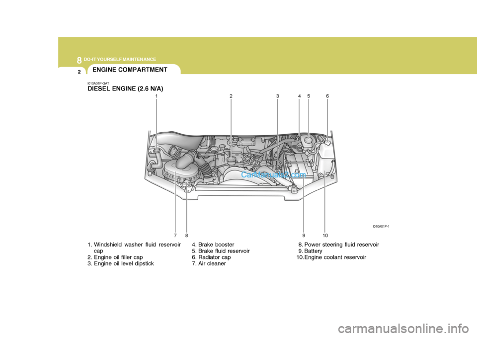
1. Windshield washer fluid reservoir cap
2. Engine oil filler cap
3. Engine oil level dipstick
I010A01P-GAT DIESEL ENGINE (2.6 N/A)
4. Brake booster
5. Brake fluid reservoir
6. Radiator cap
7. Air cleaner 8. Power steering fluid reservoir
9. Battery
10.Engine coolant reservoirI010A01P-1
Page 249 of 284
8
DO-IT YOURSELF MAINTENANCE
3
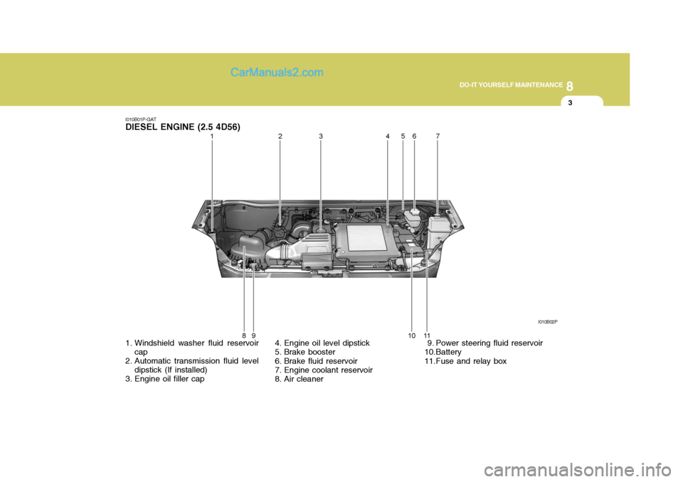
I010B01P-GAT
DIESEL ENGINE (2.5 4D56)
1. Windshield washer fluid reservoir cap
2. Automatic transmission fluid level dipstick (If installed)
3. Engine oil filler cap 4. Engine oil level dipstick
5. Brake booster
6. Brake fluid reservoir
7. Engine coolant reservoir
8. Air cleaner 9. Power steering fluid reservoir
10.Battery
11.Fuse and relay boxI010B02P
Page 250 of 284
8DO-IT YOURSELF MAINTENANCE
4
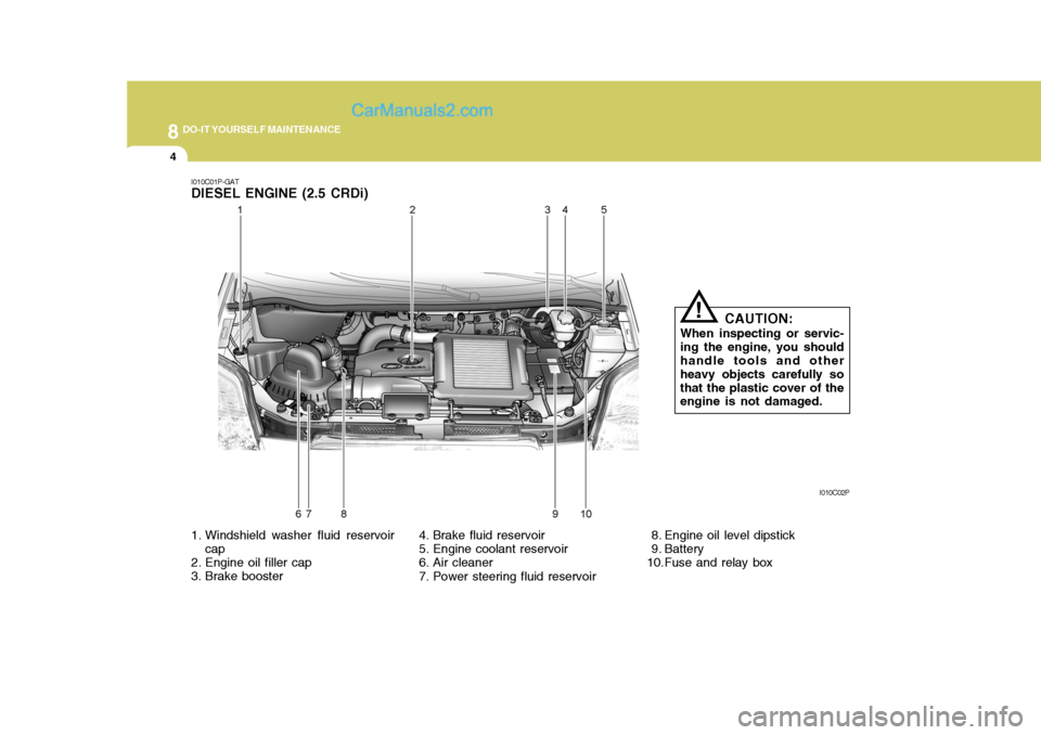
I010C01P-GAT DIESEL ENGINE (2.5 CRDi)
1. Windshield washer fluid reservoircap
2. Engine oil filler cap
3. Brake booster 4. Brake fluid reservoir
5. Engine coolant reservoir
6. Air cleaner
7. Power steering fluid reservoir 8. Engine oil level dipstick
9. Battery
10.Fuse and relay boxI010C02P
CAUTION:
When inspecting or servic-ing the engine, you should handle tools and other heavy objects carefully sothat the plastic cover of the engine is not damaged.
!