test HYUNDAI IX35 2014 User Guide
[x] Cancel search | Manufacturer: HYUNDAI, Model Year: 2014, Model line: IX35, Model: HYUNDAI IX35 2014Pages: 1534, PDF Size: 39.76 MB
Page 332 of 1534
Maintenance
38
7
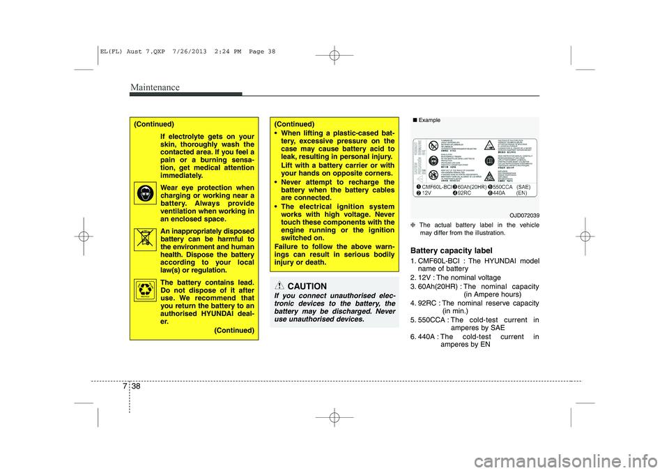
❈ The actual battery label in the vehicle
may differ from the illustration.
Battery capacity label
1. CMF60L-BCI : The HYUNDAI model name of battery
2. 12V : The nominal voltage
3. 60Ah(20HR) : The nominal capacity
(in Ampere hours)
4. 92RC : The nominal reserve capacity (in min.)
5. 550CCA : The cold-test current in
amperes by SAE
6. 440A : The cold-test current in
amperes by EN
(Continued)
When lifting a plastic-cased bat- tery, excessive pressure on the
case may cause battery acid to
leak, resulting in personal injury.
Lift with a battery carrier or with
your hands on opposite corners.
Never attempt to recharge the battery when the battery cablesare connected.
The electrical ignition system works with high voltage. Never
touch these components with theengine running or the ignition
switched on.
Failure to follow the above warn-
ings can result in serious bodily
injury or death.(Continued)
If electrolyte gets on your
skin, thoroughly wash the
contacted area. If you feel a
pain or a burning sensa-
tion, get medical attention
immediately.
Wear eye protection whencharging or working near a
battery. Always provide
ventilation when working in
an enclosed space.
An inappropriately disposed battery can be harmful to
the environment and human
health. Dispose the battery
according to your local
law(s) or regulation.
The battery contains lead.
Do not dispose of it after
use. We recommend that
you return the battery to an
authorised HYUNDAI deal-
er.
(Continued)
Pb
CAUTION
If you connect unauthorised elec-tronic devices to the battery, the battery may be discharged. Neveruse unauthorised devices.
OJD072039
■
Example
EL(FL) Aust 7.QXP 7/26/2013 2:24 PM Page 38
Page 342 of 1534
Maintenance
48
7
4. Tyre ply composition and material
The number of layers or plies of rub-
ber-coated fabric are in the tyre. Tyre
manufacturers also must indicate the
materials in the tyre, which include
steel, nylon, polyester, and others.
The letter "R" means radial ply con-
struction; the letter "D" means diago-
nal or bias ply construction; and theletter "B" means belted-bias ply con-
struction.
5. Maximum permissible inflation
pressure
This number is the greatest amount of air pressure that should be put in
the tyre. Do not exceed the maximum
permissible inflation pressure. Refer
to the Tyre and Loading Information
label for recommended inflation
pressure.
6. Maximum load rating
This number indicates the maximum
load in kilograms and pounds that
can be carried by the tyre. When
replacing the tyres on the vehicle,
always use a tyre that has the same
load rating as the factory installed
tyre.
7. Uniform tyre quality grading
Quality grades can be found where
applicable on the tyre sidewall
between tread shoulder and maxi-
mum section width.
For example:
TREADWEAR 200
TRACTION AA
TEMPERATURE A Tread wear
The tread wear grade is a compara-
tive rating based on the wear rate ofthe tyre when tested under controlled
conditions on a specified govern-
ment test course. For example, a tyre
graded 150 would wear one-and-a-
half times (1½) as well on the gov-
ernment course as a tyre graded100.
The relative performance of tyres depends upon the actual conditions
of their use, however, and may
depart significantly from the norm
because of variations in driving
habits, service practices and differ-
ences in road characteristics and cli-
mate.
These grades are molded on the
side-walls of passenger vehicle
tyres. The tyres available as standard
or optional equipment on your vehi-
cles may vary with respect to grade.
WARNING - Tyre age
Tyres degrade over time, even
when they are not being used.
Regardless of the remaining
tread, it is recommended that
tyres generally be replaced
after six (6) years of normal
service. Heat caused by hot cli-mates or frequent high loadingconditions can accelerate the
aging process. Failure to follow
this Warning can result in sud-
den tyre failure, which could
lead to a loss of control and an
accident involving serious
injury or death.
EL(FL) Aust 7.QXP 7/26/2013 2:24 PM Page 48
Page 343 of 1534
749
Maintenance
Traction - AA, A, B & C
The traction grades, from highest to
lowest, are AA, A, B and C. Those
grades represent the tyres ability to
stop on wet pavement as measuredunder controlled conditions on spec-
ified government test surfaces of
asphalt and concrete. A tyre marked
C may have poor traction perform-
ance.Temperature -A, B & C
The temperature grades are A (the highest), B and C representing the
tyre’s resistance to the generation ofheat and its ability to dissipate heatwhen tested under controlled condi-
tions on a specified indoor laboratorytest wheel.
Sustained high temperature can
cause the material of the tyre to
degenerate and reduce tyre life, and
excessive temperature can lead to
sudden tyre failure. Grades B and A
represent higher levels of perform-
ance on the laboratory test wheel
than the minimum required by the
law.
WARNING
The traction grade assigned to this tyre is based on straight-ahead braking traction tests,
and does not include accelera-
tion, cornering, hydroplaning,
or peak traction characteristics.
WARNING - Tyre temperature
The temperature grade for this
tyre is established for a tyre that
is properly inflated and not
overloaded. Excessive speed,
underinflation, or excessive
loading, either separately or in
combination, can cause heat
build-up and possible sudden
tyre failure. This can cause loss
of vehicle control and serious
injury or death.
EL(FL) Aust 7.QXP 7/26/2013 2:24 PM Page 49
Page 361 of 1534
767
Maintenance
Front fog light bulbs (if equipped)
1. Remove the front bumper under cover.
2. Reach your hand into the back of thefront bumper.
3. Disconnect the power connector from the socket.
4. Remove the bulb-socket from the housing by turning the socket counter
clockwise until the tabs on the socketalign with the slots on the housing.
5. Install the new bulb-socket into the housing by aligning the tabs on the
socket with the slots in the housing.
Push the socket into the housing and
turn the socket clockwise.
6. Connect the power connector to the socket.
7. Reinstall the front bumper under cover. Headlight and front fog light aim- ing
Headlight aiming
1. Inflate the tyres to the specified pres-
sure and remove any loads from the
vehicle except the driver, spare tyre,
and tools.
2. The vehicle should be placed on a flat floor.
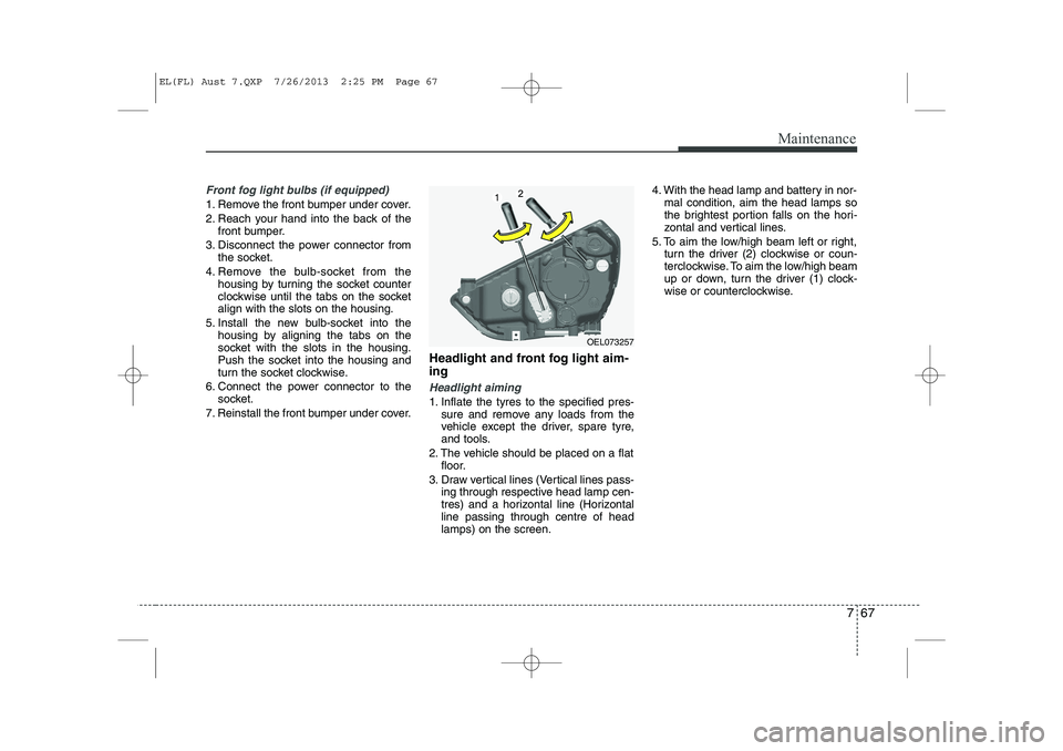
3. Draw vertical lines (Vertical lines pass- ing through respective head lamp cen-
tres) and a horizontal line (Horizontalline passing through centre of headlamps) on the screen. 4. With the head lamp and battery in nor-
mal condition, aim the head lamps so
the brightest portion falls on the hori-
zontal and vertical lines.
5. To aim the low/high beam left or right, turn the driver (2) clockwise or coun-
terclockwise. To aim the low/high beam
up or down, turn the driver (1) clock-
wise or counterclockwise.
OEL073257
EL(FL) Aust 7.QXP 7/26/2013 2:25 PM Page 67
Page 371 of 1534
777
Maintenance
APPEARANCE CARE
Exterior care
Exterior general caution
It is very important to follow the label
directions when using any chemical
cleaner or polish. Read all warning andcaution statements that appear on thelabel.
Finish maintenance
Washing
To help protect your vehicle’s finish from
rust and deterioration, wash it thoroughlyand frequently at least once a month with
lukewarm or cold water.
If you use your vehicle for off-road driv-
ing, you should wash it after each off-
road trip. Pay special attention to the
removal of any accumulation of salt, dirt,
mud, and other foreign materials. Make
sure the drain holes in the lower edges of
the doors and rocker panels are keptclear and clean.
Insects, tar, tree sap, bird droppings,
industrial pollution and similar deposits
can damage your vehicle’s finish if not
removed immediately.
Even prompt washing with plain water
may not completely remove all these
deposits.
A mild soap, safe for use on painted sur-
faces, may be used.
After washing, rinse the vehicle thor-
oughly with lukewarm or cold water. Do
not allow soap to dry on the finish.
WARNING - Wet brakes
After washing the vehicle, test the
brakes whilst driving slowly to see
if they have been affected by water.
If braking performance is impaired,
dry the brakes by applying them
lightly whilst maintaining a slow
forward speed.
CAUTION
Do not use strong soap, chemical detergents or hot water, and do
not wash the vehicle in directsunlight or when the body of thevehicle is warm.
Be careful when washing the side windows of your vehicle.Especially, with high-pressure water, water may leak through thewindows and wet the interior.
To prevent damage to the plastic parts and lamps, do not cleanwith chemical solvents or strong detergents.
EL(FL) Aust 7.QXP 7/26/2013 2:26 PM Page 77
Page 373 of 1534
779
Maintenance
Bright-metal maintenance
To remove road tar and insects, use atar remover, not a scraper or other
sharp object.
To protect the surfaces of bright-metal parts from corrosion, apply a coating of
wax or chrome preservative and rub to
a high luster.
During winter weather or in coastal areas, cover the bright metal parts with
a heavier coating of wax or preserva-
tive. If necessary, coat the parts with
non-corrosive petroleum jelly or other
protective compound.
Underbody maintenance
Corrosive materials used for ice and
snow removal and dust control may col-
lect on the underbody. If these materials
are not removed, accelerated rusting can
occur on underbody parts such as the
fuel lines, frame, floor pan and exhaust
system, even though they have been
treated with rust protection.
Thoroughly flush the vehicle underbody
and wheel openings with lukewarm or
cold water once a month, after off-road
driving and at the end of each winter. Payspecial attention to these areas because
it is difficult to see all the mud and dirt. It
will do more harm than good to wet down
the road grime without removing it. The
lower edges of doors, rocker panels, and
frame members have drain holes that
should not be allowed to clog with dirt;
trapped water in these areas can cause
rusting.WARNING
After washing the vehicle, test the
brakes whilst driving slowly to see
if they have been affected by water.
If braking performance is impaired,
dry the brakes by applying them
lightly whilst maintaining a slow
forward speed.
EL(FL) Aust 7.QXP 7/26/2013 2:26 PM Page 79
Page 377 of 1534
783
Maintenance
EMISSION CONTROL SYSTEM
The emission control system of your
vehicle is covered by a written limited
warranty. Please see the warranty infor-
mation contained in the Service Passport
in your vehicle.
Your vehicle is equipped with an emis-
sion control system to meet all Australian
Design Rules (ADR) requirements. There are three emission control sys-
tems which are as follows.
(1) Crankcase emission control system
(2) Evaporative emission control system(3) Exhaust emission control system In order to assure the proper function of
the emission control systems, it is rec-
ommended that you have your car
inspected and maintained by an autho-
rised HYUNDAI dealer or other repairshops that use qualified technicians inaccordance with the maintenance sched-
ule in this manual. Caution for the Inspection and
Maintenance Test (With ElectronicStability Contol (ESC) system)
To prevent the vehicle from misfir-
ing during dynamometer testing,
turn the Electronic Stability Contol
(ESC) system off by pressing the
ESC switch.
After dynamometer testing is com- pleted, turn the ESC system back on
by pressing the ESC switch again.
1. Crankcase emission control system
The positive crankcase ventilation sys-
tem is employed to prevent air pollution
caused by blow-by gases being emitted
from the crankcase. This system supplies
fresh filtered air to the crankcase through
the air intake hose. Inside the crankcase,
the fresh air mixes with blow-by gases,
which then pass through the PCV valveinto the induction system. 2. Evaporative emission control
System
The Evaporative Emission Control
System is designed to prevent fuel
vapours from escaping into the atmos-
phere.
Canister
Fuel vapours generated inside the fuel tank are absorbed and stored in the
onboard canister. When the engine is
running, the fuel vapours absorbed in the
canister are drawn into the surge tank
through the purge control solenoid valve.
Purge Control Solenoid Valve (PCSV)
The purge control solenoid valve is con-
trolled by the Engine Control Module
(ECM); when the engine coolant temper-
ature is low during idling, the PCSV clos-
es so that evaporated fuel is not taken
into the engine. After the engine warms-
up during ordinary driving, the PCSV
opens to introduce evaporated fuel to the
engine.
EL(FL) Aust 7.QXP 7/26/2013 2:26 PM Page 83
Page 395 of 1534
F5
The compliance plate shows that your vehicle has been tested and found to comply with all relevant
Australian Design Rules (ADR's) applicable at its date of manufacture.
Any part, that is subject to these ADR's, must not be removed or altered and is to be maintained in
good order at all times for the vehicle to be roadworthy and re-registerable by all registerable author-
ities.
Consult an Authorised Hyundai Dealer before conducting any repairs that may affect these areas or
if requiring further classification on design rules or safety features. Failure to observe the above warn-
ing may render the vehicle compliance invalid and result in personal injury which may have otherwise
been avoided.
AUSTRALIAN DESIGN RULES
EL(FL) Aust FOREWORD.QXP 7/26/2013 1:59 PM Page 5
Page 410 of 1534
Introduction
2
1
We want to help you get the greatest
possible driving pleasure from your vehi-
cle. Your Owner’s Manual can assist you
in many ways. We strongly recommend
that you read the entire manual. In order
to minimize the chance of death or injury,
you must read the WARNING and CAU-
TION sections in the manual.
Illustrations complement the words in this
manual to best explain how to enjoy your
vehicle. By reading your manual, you will
learn about features, important safety
information, and driving tips under vari-
ous road conditions.
The general layout of the manual is pro-
vided in the Table of Contents. A good
place to start is the index; it has an alpha-
betical listing of all information in your
manual.
Sections: This manual has eight sections
plus an index. Each section begins with a
brief list of contents so you can tell at a
glance if that section has the information
you want. You’ll find various WARNINGS, CAU-
TIONS, and NOTICES in this manual.
These were prepared to enhance your
personal safety. You should carefully read
and follow ALL procedures and recom-
mendations provided in these WARN-
INGS, CAUTIONS and NOTICES.
✽✽
NOTICE
A NOTICE indicates interesting or help-
ful information is being provided.
Gasoline engine
Unleaded
For Europe
For the optimal vehicle performance, we
recommend you to use unleaded gaso-line which complies with EN 228 and has
an octane rating of RON (Research
Octane Number) 95 / AKI (Anti Knock
Index) 91 or higher. You may use unlead-
ed gasoline with an octane rating of RON
91-94 / AKI 87-90 but it may result in
slight performance reduction of the vehi-
cle.
Except Europe
Your new vehicle is designed to use only
unleaded fuel having an Octane Rating
of RON (Research Octane Number) 91 /
AKI (Anti-Knock Index) 87 or higher.
Your new vehicle is designed to obtain
maximum performance with UNLEADED
FUEL, as well as minimize exhaust emis-
sions and spark plug fouling.
HOW TO USE THIS MANUAL
WARNING
A WARNING indicates a situation in
which harm, serious bodily injury ordeath could result if the warning isignored.
CAUTION
A CAUTION indicates a situation in which damage to your vehicle couldresult if the caution is ignored.
FUEL REQUIREMENTS
EL(FL) Eng 1.QXP 8/8/2013 6:52 PM Page 2
Page 413 of 1534
15
Introduction
Biodiesel
Commercially supplied Diesel blends of no more than 7% biodiesel, commonly
known as "B7 Diesel" may be used in
your vehicle if Biodiesel meets EN 14214
or equivalent specifications. (EN stands
for "European Norm"). The use of biofu-
els exceeding 7% made from rapeseed
methyl ester (RME), fatty acid methyl
ester (FAME), vegetable oil methyl ester
(VME) etc. or mixing diesel exceeding7% with biodiesel will cause increased
wear or damage to the engine and fuel
system. Repair or replacement of worn ordamaged components due to the use of
non approved fuels will not be covered by
the manufactures warranty.CAUTION
Do not let any gasoline or waterenter the tank. This would make it
necessary to drain it out and to bleed the lines to avoid jammingthe injection pump and damagingthe engine.
In winter, in order to cut down incidents due to freezing, paraffinoil may be added to the fuel if thetemperature drops to below -10°C
(14°F). Never use more than 20% paraffin oil.
CAUTION - Diesel Fuel
It is recommended to use the regu-
lated automotive diesel fuel fordiesel vehicle equipped with the DPF system.
If you use diesel fuel including highsulfur (more than 50 ppm sulfur)and unspecified additives, it can cause the DPF system to be dam-aged and white smoke can be emit-
ted.CAUTION
Never use any fuel, whether diesel, B7 biodiesel or otherwise,that fails to meet the latest petro-leum industry specification.
Never use any fuel additives or treatments that are not recom-mended or approved by the vehi- cle manufacturer.
EL(FL) Eng 1.QXP 8/8/2013 6:52 PM Page 5