battery location Hyundai Kona EV 2019 Owner's Manual
[x] Cancel search | Manufacturer: HYUNDAI, Model Year: 2019, Model line: Kona EV, Model: Hyundai Kona EV 2019Pages: 540, PDF Size: 21.84 MB
Page 91 of 540
3-7
Convenient features of your vehicle
3
When possible, avoid keeping the
remote key and your mobile phone in
the same location such as a pants or
jacket pocket in order to avoid inter-
ference between the two devices.
Keep the smart key away from
electromagnetic materials that
block electromagnetic waves to
the key surface.
Always have the smart key with
you when leaving the vehicle. If
the smart key is left near the vehi-
cle, the vehicle battery may be dis-
charged.Information
This device complies with Part 15 of
the FCC rules.
Operation is subject to the following
three conditions:
1. This device may not cause harmfulinterference.
2. This device must accept any inter- ference received, including inter-
ference that may cause undesired
operation.
3. Changes or modifications not expressly approved by the party
responsible for compliance could
void the user's authority to operate
the device.
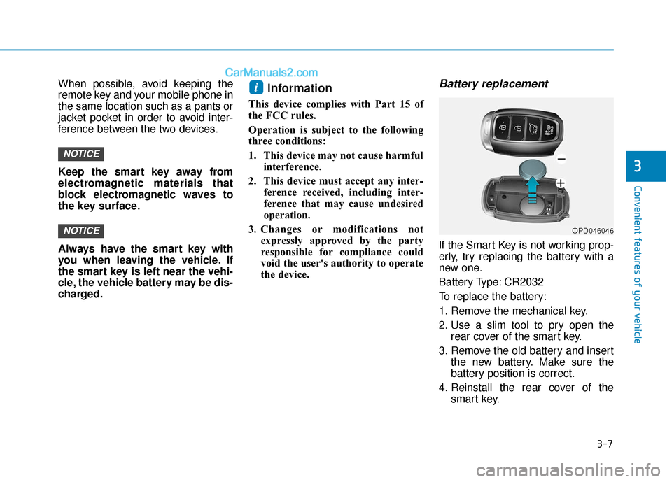
Battery replacement
If the Smart Key is not working prop-
erly, try replacing the battery with a
new one.
Battery Type: CR2032
To replace the battery:
1. Remove the mechanical key.
2. Use a slim tool to pry open therear cover of the smart key.
3. Remove the old battery and insert the new battery. Make sure the
battery position is correct.
4. Reinstall the rear cover of the smart key.
i
NOTICE
NOTICE
OPD046046
Page 131 of 540
3-47
Convenient features of your vehicle
3
Toque gauge
The torque gauge shows the real-
time torque value while driving when
SPORT mode is selected by press-
ing the DRIVE MODE button.
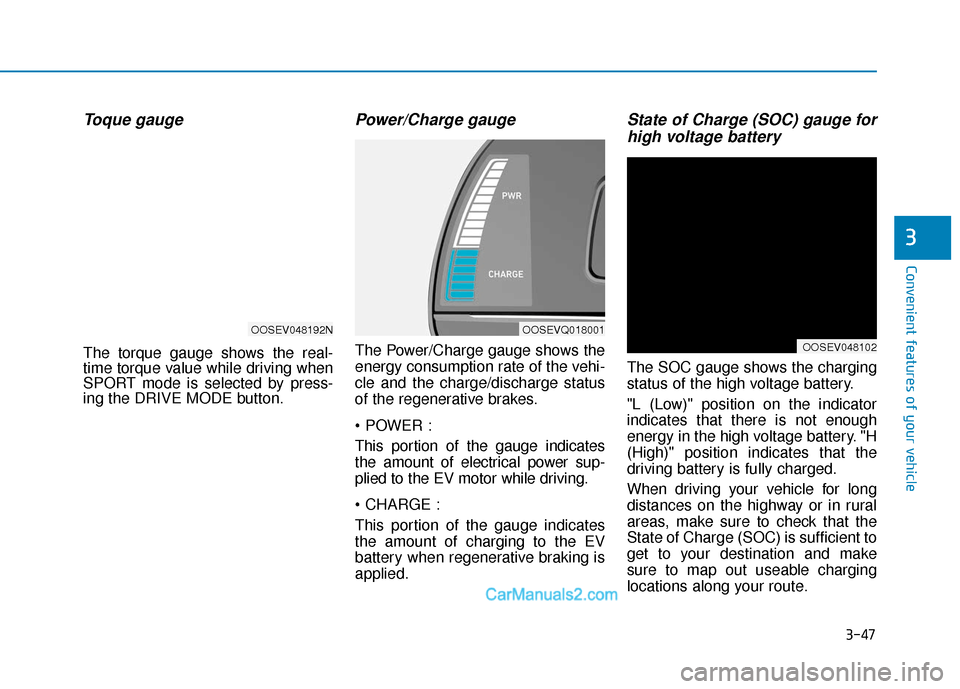
Power/Charge gauge
The Power/Charge gauge shows the
energy consumption rate of the vehi-
cle and the charge/discharge status
of the regenerative brakes.
This portion of the gauge indicates
the amount of electrical power sup-
plied to the EV motor while driving.
This portion of the gauge indicates
the amount of charging to the EV
battery when regenerative braking is
applied.
State of Charge (SOC) gauge forhigh voltage battery
The SOC gauge shows the charging
status of the high voltage battery.
"L (Low)" position on the indicator
indicates that there is not enough
energy in the high voltage battery. "H
(High)" position indicates that the
driving battery is fully charged.
When driving your vehicle for long
distances on the highway or in rural
areas, make sure to check that the
State of Charge (SOC) is sufficient to
get to your destination and make
sure to map out useable charging
locations along your route.
OOSEVQ018001
OOSEV048102
OOSEV048192N
Page 133 of 540
3-49
Convenient features of your vehicle
3
Odometer
The odometer indicates the total dis-
tance that the vehicle has been driv-
en and should be used to determine
when periodic maintenance should
be performed.
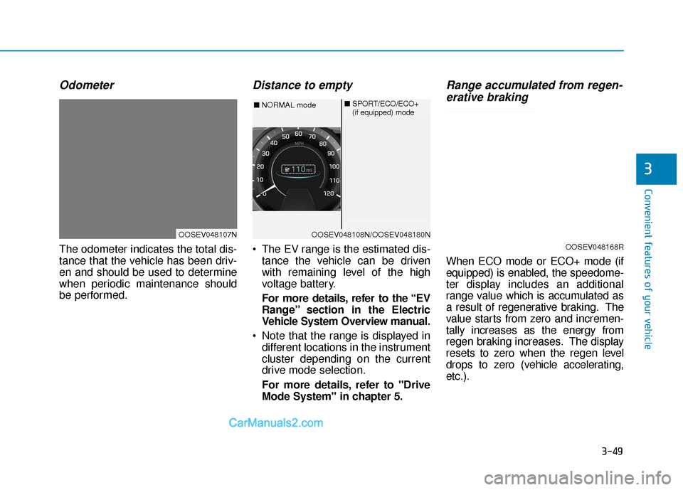
Distance to empty
The EV range is the estimated dis-tance the vehicle can be driven
with remaining level of the high
voltage battery.
For more details, refer to the “EV
Range” section in the Electric
Vehicle System Overview manual.
Note that the range is displayed in different locations in the instrument
cluster depending on the current
drive mode selection.
For more details, refer to "Drive
Mode System" in chapter 5.
Range accumulated from regen-erative braking
When ECO mode or ECO+ mode (if
equipped) is enabled, the speedome-
ter display includes an additional
range value which is accumulated as
a result of regenerative braking. The
value starts from zero and incremen-
tally increases as the energy from
regen braking increases. The display
resets to zero when the regen level
drops to zero (vehicle accelerating,
etc.).
OOSEV048107NOOSEV048108N/OOSEV048180N
■ NORMAL mode ■
SPORT/ECO/ECO+
(if equipped) mode
OOSEV048168R
Page 140 of 540
3-56
Convenient features of your vehicle
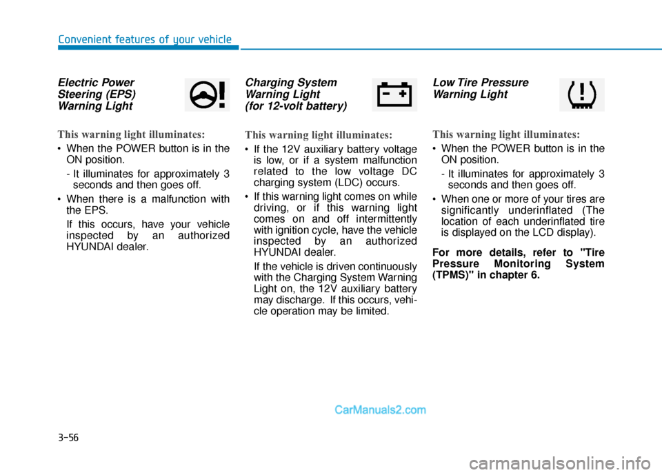
Electric PowerSteering (EPS)Warning Light
This warning light illuminates:
When the POWER button is in the
ON position.
- It illuminates for approximately 3seconds and then goes off.
When there is a malfunction with the EPS.
If this occurs, have your vehicle
inspected by an authorized
HYUNDAI dealer.
Charging SystemWarning Light(for 12-volt battery)
This warning light illuminates:
If the 12V auxiliary battery voltage
is low, or if a system malfunction
related to the low voltage DC
charging system (LDC) occurs.
If this warning light comes on while driving, or if this warning light
comes on and off intermittently
with ignition cycle, have the vehicle
inspected by an authorized
HYUNDAI dealer.
If the vehicle is driven continuously
with the Charging System Warning
Light on, the 12V auxiliary battery
may discharge. If this occurs, vehi-
cle operation may be limited.
Low Tire PressureWarning Light
This warning light illuminates:
When the POWER button is in the
ON position.
- It illuminates for approximately 3seconds and then goes off.
When one or more of your tires are significantly underinflated (The
location of each underinflated tire
is displayed on the LCD display).
For more details, refer to "Tire
Pressure Monitoring System
(TPMS)" in chapter 6.
Page 158 of 540
3-74
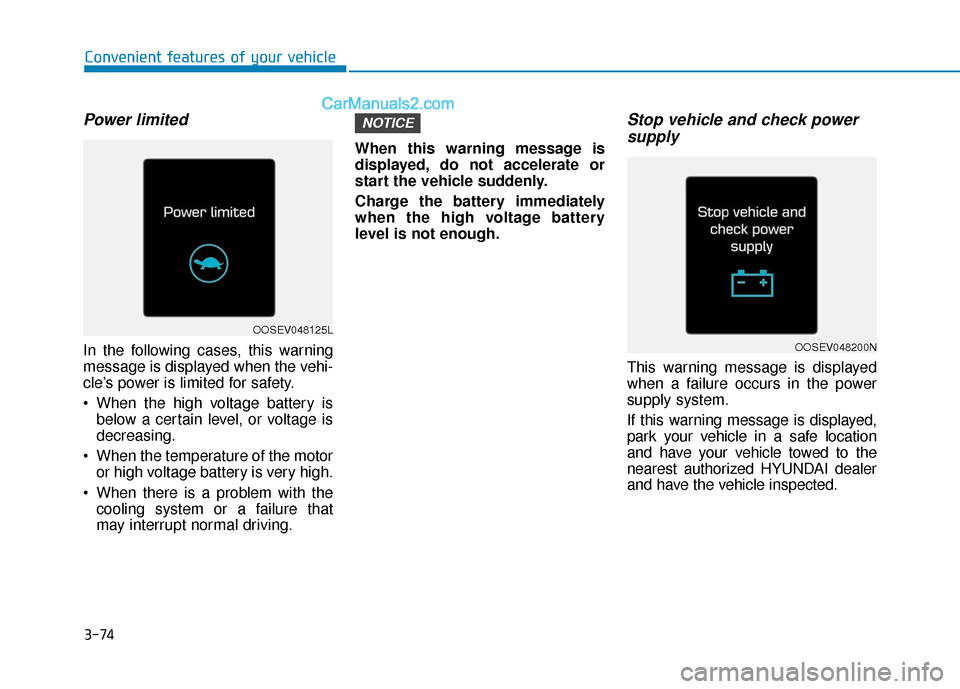
Power limited
In the following cases, this warning
message is displayed when the vehi-
cle’s power is limited for safety.
When the high voltage battery isbelow a certain level, or voltage is
decreasing.
When the temperature of the motor or high voltage battery is very high.
When there is a problem with the cooling system or a failure that
may interrupt normal driving. When this warning message is
displayed, do not accelerate or
start the vehicle suddenly.
Charge the battery immediately
when the high voltage battery
level is not enough.
Stop vehicle and check power
supply
This warning message is displayed
when a failure occurs in the power
supply system.
If this warning message is displayed,
park your vehicle in a safe location
and have your vehicle towed to the
nearest authorized HYUNDAI dealer
and have the vehicle inspected.
NOTICE
Convenient features of your vehicle
OOSEV048200N
OOSEV048125L
Page 206 of 540
3-122
Convenient features of your vehicle
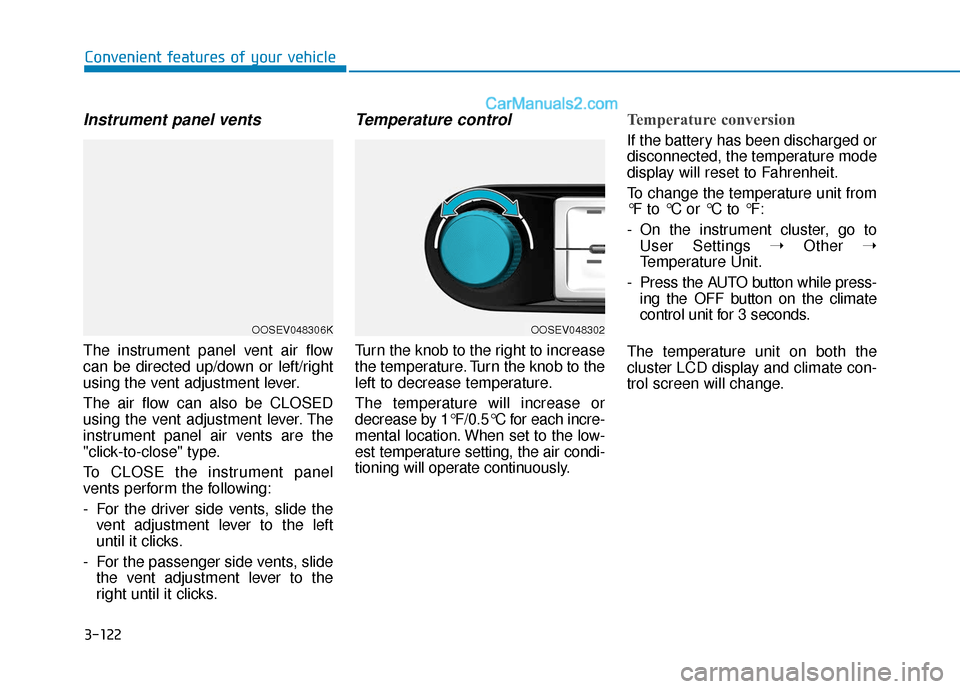
Instrument panel vents
The instrument panel vent air flow
can be directed up/down or left/right
using the vent adjustment lever.
The air flow can also be CLOSED
using the vent adjustment lever. The
instrument panel air vents are the
"click-to-close" type.
To CLOSE the instrument panel
vents perform the following:
- For the driver side vents, slide thevent adjustment lever to the left
until it clicks.
- For the passenger side vents, slide the vent adjustment lever to the
right until it clicks.
Temperature control
Turn the knob to the right to increase
the temperature. Turn the knob to the
left to decrease temperature.
The temperature will increase or
decrease by 1°F/0.5°C for each incre-
mental location. When set to the low-
est temperature setting, the air condi-
tioning will operate continuously.
Temperature conversion
If the battery has been discharged or
disconnected, the temperature mode
display will reset to Fahrenheit.
To change the temperature unit from
°F to °C or °C to °F:
- On the instrument cluster, go toUser Settings ➝ Other ➝
Temperature Unit.
- Press the AUTO button while press- ing the OFF button on the climate
control unit for 3 seconds.
The temperature unit on both the
cluster LCD display and climate con-
trol screen will change.
OOSEV048306KOOSEV048302
Page 464 of 540
E
El
le
e c
ct
tr
r i
ic
c
V
V e
eh
h i
ic
c l
le
e
S
S y
ys
st
te
e m
m
O
O v
ve
e r
rv
v i
ie
e w
w
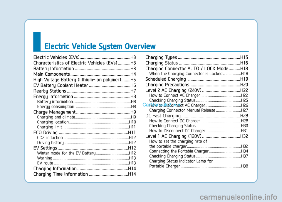
Electric Vehicles (EVs)............................................H3
Characteristics of Electric Vehicles (EVs) ...........H3
Battery Information ................................................H3
Main Components ....................................................H4
High Voltage Battery (lithium-ion polymer)........H5
EV Battery Coolant Heater ....................................H6
Nearby Stations .......................................................H7
Energy Information .................................................H8
Battery information ............................................................H8
Energy consumption .........................................................H8
Charge Management ...............................................H9
Charging and climate........................................................\
..H9
Charging location ..............................................................H10
Charging limit .....................................................................H11\
ECO Driving ............................................................H11
CO2 reduction ....................................................................H12
Driving history ...................................................................H12
EV Settings .............................................................H12
Winter mode for the EV Battery ..................................H12
Warning ........................................................................\
.......H13
EV route ........................................................................\
......H13
Charging Information ............................................H14
Charging Time Information ..................................H14 Charging Types ......................................................H15
Charging Status .....................................................H16
Charging Connector AUTO / LOCK Mode ..........H18
When the Charging Connector is Locked ...................H18
Scheduled Charging .............................................H19
Charging Precautions............................................H20
Level 2 AC Charging (240V) .................................H22
How to Connect AC Charger ..........................................H22
Checking Charging Status ...............................................H25
How to Disconnect AC Charger.....................................H26
Charging Connector Manual Release ..........................H27
DC Fast Charging ...................................................H28
How to Connect DC Charger ..........................................H28
Checking Charging Status ...............................................H30
How to Disconnect DC Charger.....................................H31
Level 1 AC Charging (120V) .................................H32
How to set the charging rate of
the portable charger ........................................................H32
Connecting the Portable Charger .................................H34
Checking Charging Status ...............................................H37
Charging Status Indicator Lamp for
Portable Charger ...............................................................H38
Page 472 of 540
H9
➃‘Battery care’ shows the momen-
tary power and energy consump-
tion which are used when:
increase the battery temperature
during winter to improve the driv-
ing performance.
ature during summer to prevent
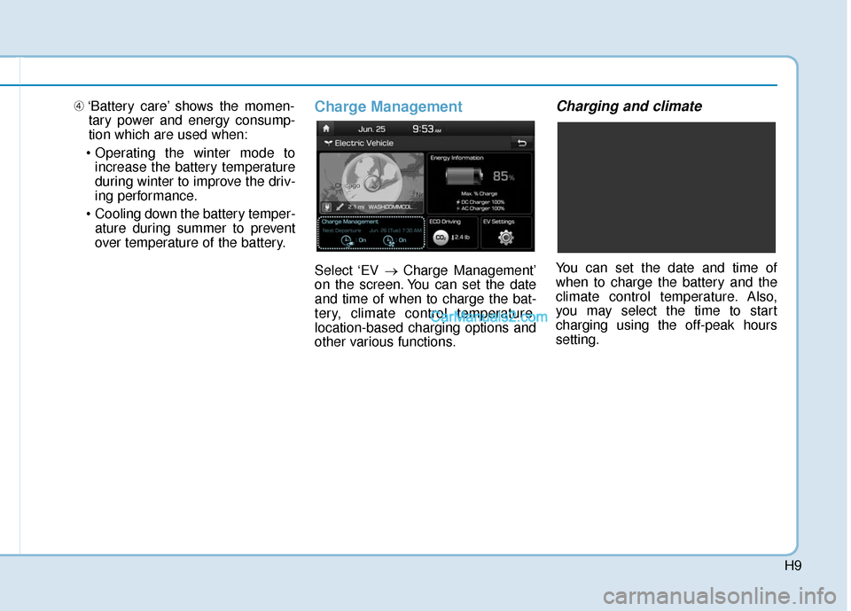
over temperature of the battery.Charge Management
Select ‘EV → Charge Management’
on the screen. You can set the date
and time of when to charge the bat-
tery, climate control temperature,
location-based charging options and
other various functions.
Charging and climate
You can set the date and time of
when to charge the battery and the
climate control temperature. Also,
you may select the time to start
charging using the off-peak hours
setting.
Page 510 of 540
H47
Tips for Improving Range
While Driving
Depress and hold the acceleratorpedal to maintain speed and drive
economically.
Gradually depress and release the accelerator pedal when accelerat-
ing or decelerating.
Always maintain specified tire pressures.
Do not use unnecessary electrical components while driving.
Do not load unnecessary items in the vehicle.
Do not mount parts that may increase air resistance.
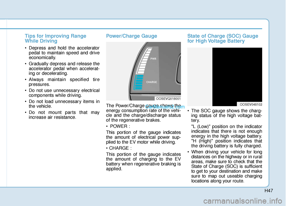
Power/Charge Gauge
The Power/Charge gauge shows the
energy consumption rate of the vehi-
cle and the charge/discharge status
of the regenerative brakes.
POWER :
This portion of the gauge indicates
the amount of electrical power sup-
plied to the EV motor while driving.
This portion of the gauge indicates
the amount of charging to the EV
battery when regenerative braking is
applied.
State of Charge (SOC) Gauge
for High Voltage Battery
The SOC gauge shows the charg-ing status of the high voltage bat-
tery.
"L (Low)" position on the indicator
indicates that there is not enough
energy in the high voltage battery.
"H (High)" position indicates that
the driving battery is fully charged.
When driving your vehicle for long distances on the highway or in rural
areas, make sure to check that the
State of Charge (SOC) is sufficient
to get to your destination and make
sure to map out useable charging
locations along your route.
OOSEVQ018001
OOSEV048102