engine coolant Hyundai Matrix 2003 Owner's Guide
[x] Cancel search | Manufacturer: HYUNDAI, Model Year: 2003, Model line: Matrix, Model: Hyundai Matrix 2003Pages: 312, PDF Size: 4.1 MB
Page 156 of 312

DO-IT-YOURSELF MAINTENANCE 6-23
G290A01FC-GAT
HEADLIGHT AIMING ADJUSTMENT
Before performing aiming adjustment, make sure of the following.
1. Keep all tires inflated to the correct pres- sure.
2. Place the vehicle on level ground and press the front bumper and rear bumper downseveral times. Place the vehicle at a dis-tance of 3,000 mm (118 in.) from the testwall.
3. See that the vehicle is unloaded (except for full levels of coolant, engine oil and fuel, andspare tire, jack, and tools).
4. Clean the head lights lens and turn on the headlight (low beam).
G290A01FC
Horizontal Aiming
5. Push the bulb spring for removing the head-
light bulb.
6. Remove the protective cap from the replace- ment bulb and install the new bulb by match- ing the plastic base with the headlight hole.Install the dust cover after retightening thebulb spring and reconnect the power cord.
7. Use the protective cap and carton to dis- pose of the old bulb.
8. Check for proper headlight aim.
WARNING The halogen bulb contains gas under pres-
sure and if impacted could shatter, resulting in flying fragments. Always wear eye pro-tection when servicing the bulb. Protect thebulb against abrasions or scratches andagainst liquids when lighted. Turn on thebulb only when installed in a headlight. Re-place the headlight if damaged or cracked.Keep the bulb out of the reach of childrenand dispose of the used bulb with care.
G270A02FC
Vertical Aiming
G270A02A-GAT
HEADLIGHT BULB Replacement instructions:
G270A01FC
1. Allow the bulb to cool. Wear eye protection.
2. Always grasp the bulb by its plastic base, avoid touching the glass.
3. Disconnect the power cord from the bulb base in the back of the headlight.
4. Remove the dust cover.
Page 162 of 312

EMISSION CONTROL SYSTEMS 7-1
7. EMISSION CON-TROL SYSTEMS
H010A01A-GAT
EMISSION CONTROL SYSTEMS (If Installed)
Your Hyundai is equipped with an emission
control system to meet all requirements of the Emission prohibition rules of your province. There are three emission control systems which
are as follows.
(1) Crankcase emission control system (2) Evaporative emission control system(3) Exhaust emission control system In order to assure the proper function of the
emission control systems, it is recommended that you have your car inspected and main-tained by an authorized Hyundai dealer in ac-cordance with the maintenance schedule in thismanual. H010D01A-AAT
3. Exhaust Emission Control System
The Exhaust Emission Control System is a
highly effective system which controls exhaustemissions while maintaining good vehicle per-formance.
H010C01E-GAT
2. Evaporative Emission Control
System
The Evaporative Emission Control System is
designed to prevent fuel vapors from escapinginto the atmosphere. Canister
While the engine is inoperative, fuel vapors
generated inside the fuel tank are absorbed and stored in the canister. When the engine isrunning, the fuel vapors absorbed in the canis-ter are drawn into the induction system through
the purge control solenoid valve.
Purge Control Solenoid Valve (PCSV) The purge control solenoid valve is controlled
by the Engine Control Module (ECM); when theengine coolant temperature is low during idling,the PCSV closes so that evaporated fuel is nottaken into the engine. After the engine warms-up during ordinary driving, the PCSV opens soas to introduce evaporated fuel to the engine. H010B01A-AAT
1. Crankcase Emission Control
System
The Positive Crankcase Ventilation System is
employed to prevent air pollution caused byblow-by gases being emitted from the crank-case. This system supplies fresh filtered air tothe crankcase through the air intake hose.Inside the crankcase, the fresh air mixes withblow-by gases, then passes through the PCVvalve into the induction system.
The catalytic converter is part of the exhaust
emission control system. Its purpose is to re-move certain engine emission products fromthe engine's exhaust. It looks something like amuffler and is located underneath the car in the
exhaust system.
H020A01A-GAT
CATALYTIC CONVERTER (If Installed); For a gasoline engine
Catalytic Converter HFC5013
7
Page 169 of 312
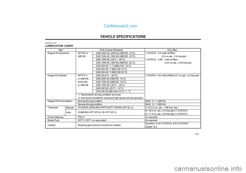
VEHICLE SPECIFICATIONS 9-3
Oil & Grease Standard
API SG or SAE 20W-40, 20W-50 (ABOVE -10°C)
ABOVE SAE 15W-40, 15W-50 (ABOVE -15°C)
SAE 10W-30 (-25°C ~ 40°C) SAE 10W-40, 10W-50 (ABOVE -25°C) SAE 5W-20 *1, *2 (BELOW -10°C)SAE 5W-30 *1 (BELOW 10°C) SAE 5W-40 *1 (BELOW 20°C)
API CF-4 SAE 30 (0°C ~ 40°C)
or ABOVE, SAE 20W-40 (ABOVE -10°C)
ACEA B4 SAE 15W-40 (ABOVE -15°C)
or ABOVE SAE 10W-30 (-20°C ~ 40°C) SAE 5W-30 (-25°C ~ 10°C) SAE 0W-30 (BELOW 10°C) *1, *2
*1. Restricted to driving condition and area *2. Not recommended for sustained high speed vehicle operation Normal driving condition Severe driving conditionHYUNDAI GENUINE PARTS MTF 75W/90 (API GL-4) DIAMOND ATF SP- III, SK ATF SP- III
PSF-3 DOT 3, DOT 4 or equivalent Ethylene glycol base for aluminum radiator
Item
Engine Oil (Gasoline) Engine Oil (Diesel)
Engine Oil Consumption Transaxle
Power Steering Brake Fluid Coolant
J080A03FC-GAT
LUBRICATION CHART
Q’ty (liter)
1.6 DOHC - 3.3 (with oil filter)
(3.5 us.qts., 2.9 Imp.qts)
1.8 DOHC - 3.85 (with oil filter) (4.07 us.qts., 3.39 Imp.qts)
1.5 SOHC - 4.8 (with oil filter) (5.1 us.qts., 4.2 Imp.qts) MAX. 1L / 1,500 Km MAX. 1L / 1,000 Km2.15 (2.3 us. qts., 1.86 Imp. qts) 6.1 (6.4 us. qts., 5.3 Imp.qts) (1.6 DOHC) 6.7 (7.0 us. qts., 5.8 Imp.qts) (1.8 DOHC)As required As required Gasoline : 6.2(1.6 DOHC), 6.5(1.8 DOHC)Diesel : 6.3
Manual Auto
Page 171 of 312
INDEX
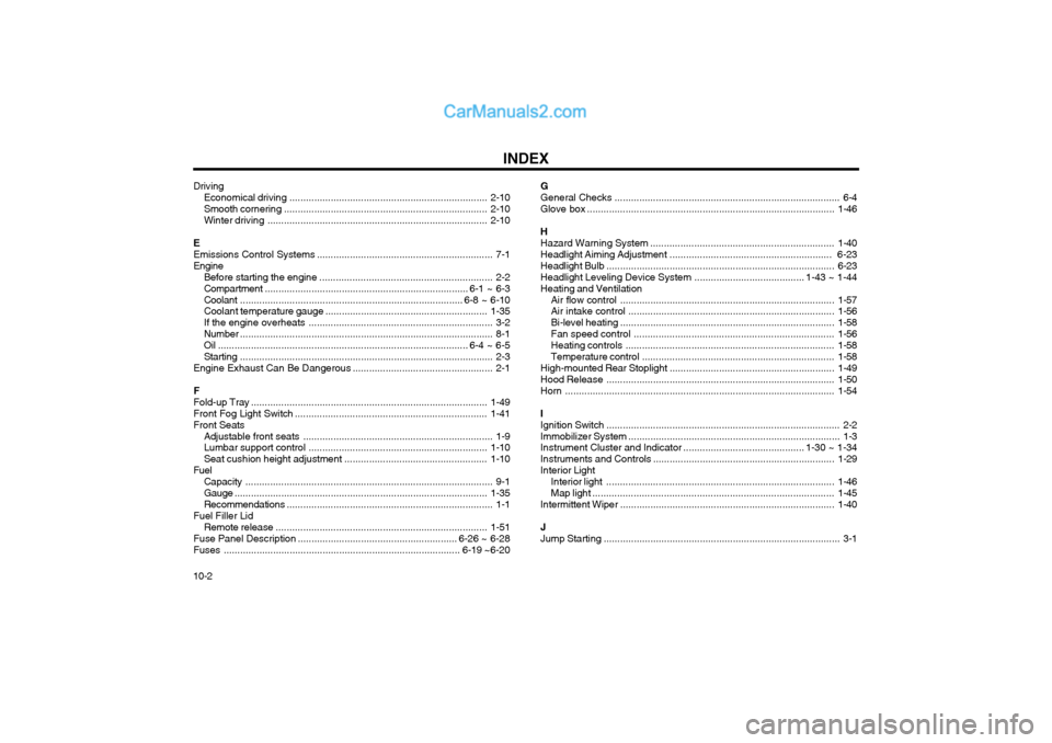
10-2 Driving
Economical dr iving ........................................................................ 2-10
Smooth cornering .......................................................................... 2-10
Winter driving ................................................................................ 2-10
E Emissions Control Systems ................................................................ 7-1
Engine Before starting the engine ............................................................... 2-2Compartment .......................................................................... 6-1 ~ 6-3
Coolant ................................................................................. 6-8 ~ 6-10
Coolant temperature gauge ........................................................... 1-35
If the engine overheats ................................................................... 3-2
Number ............................................................................................ 8-1
Oil ........................................................................................... 6-4 ~ 6-5Starting ............................................................................................ 2-3
Engine Exhaust Can Be Dangerous ................................................... 2-1
FFold-up Tray ...................................................................................... 1-49
Front Fog Light Sw itch ...................................................................... 1-41
Front Seats Adjustable front seats ..................................................................... 1-9
Lumbar support control ................................................................. 1-10
Seat cushion height adjustment .................................................... 1-10
Fuel Capacity .......................................................................................... 9-1
Gauge ............................................................................................ 1-35
Recommendations ........................................................................... 1-1
Fuel Filler Lid
Remote release ............................................................................. 1-51
Fuse Panel Description .......................................................... 6-26 ~ 6-28
Fuses ...................................................................................... 6-19 ~6-20 GGeneral Checks
.................................................................................. 6-4
Glove box .......................................................................................... 1-46
H Hazard Warning System ................................................................... 1-40
Headlight Aiming Adjustment ........................................................... 6-23
Headlight Bulb ................................................................................... 6-23
Headlight Leveling Device System ........................................ 1-43 ~ 1-44
Heating and Ventilation
Air flow control .............................................................................. 1-57
Air intake control ........................................................................... 1-56
Bi-level heating .............................................................................. 1-58
Fan speed control ......................................................................... 1-56
Heating controls ............................................................................ 1-58
Temperature control ...................................................................... 1-58
High-mounted Rear Stoplight ............................................................ 1-49
Hood Release ................................................................................... 1-50
Horn .................................................................................................. 1-54
IIgnition Switch ..................................................................................... 2-2
Immobilizer System ............................................................................. 1-3
Instrument Cluster and Indicator ............................................ 1-30 ~ 1-34
Instruments and Controls .................................................................. 1-29
Interior Light Interior light ................................................................................... 1-46
Map light ........................................................................................ 1-45
Intermittent Wiper .............................................................................. 1-40
JJump Starting ...................................................................................... 3-1
Page 213 of 312
CONTROLS AND EQUIPMENT
1- 32
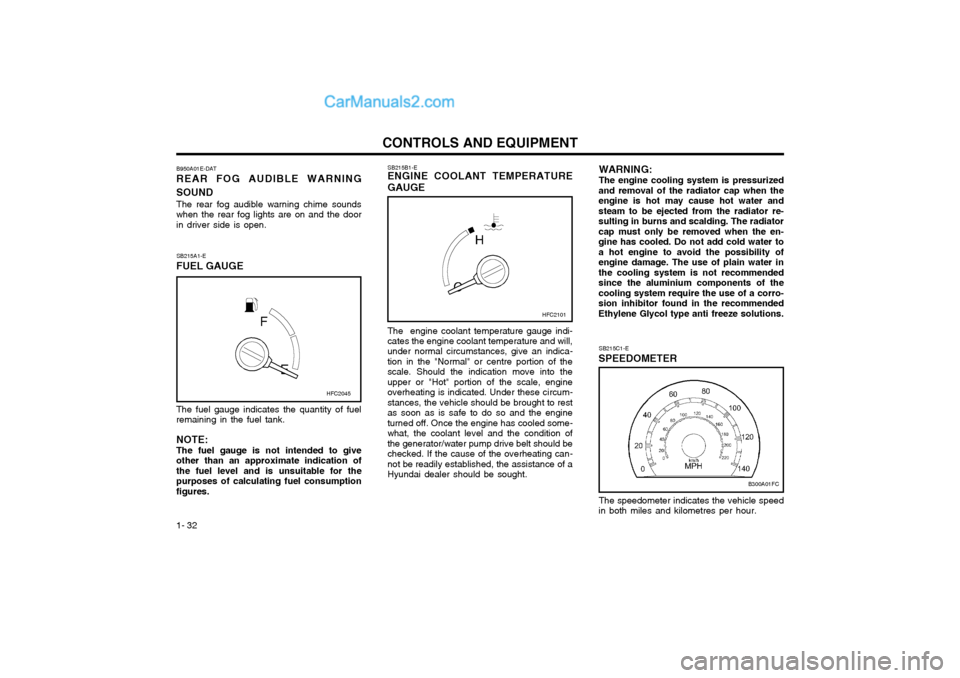
The fuel gauge indicates the quantity of fuel remaining in the fuel tank. NOTE: The fuel gauge is not intended to giveother than an approximate indication ofthe fuel level and is unsuitable for thepurposes of calculating fuel consumptionfigures. SB215B1-E
ENGINE COOLANT TEMPERATURE GAUGE
The engine coolant temperature gauge indi-
cates the engine coolant temperature and will, under normal circumstances, give an indica-tion in the "Normal" or centre portion of thescale. Should the indication move into theupper or "Hot" portion of the scale, engineoverheating is indicated. Under these circum-stances, the vehicle should be brought to restas soon as is safe to do so and the engineturned off. Once the engine has cooled some-what, the coolant level and the condition ofthe generator/water pump drive belt should bechecked. If the cause of the overheating can-not be readily established, the assistance of aHyundai dealer should be sought.
SB215A1-E
FUEL GAUGE
B950A01E-DAT REAR FOG AUDIBLE WARNING SOUND The rear fog audible warning chime sounds when the rear fog lights are on and the doorin driver side is open.
HFC2101
HFC2045
WARNING: The engine cooling system is pressurized
and removal of the radiator cap when the engine is hot may cause hot water andsteam to be ejected from the radiator re-sulting in burns and scalding. The radiatorcap must only be removed when the en-gine has cooled. Do not add cold water toa hot engine to avoid the possibility ofengine damage. The use of plain water inthe cooling system is not recommendedsince the aluminium components of thecooling system require the use of a corro-sion inhibitor found in the recommendedEthylene Glycol type anti freeze solutions.
B300A01FC
SB215C1-E
SPEEDOMETER
The speedometer indicates the vehicle speed
in both miles and kilometres per hour.
Page 254 of 312

DRIVING YOUR HYUNDAI
2- 12 NOTE: Never allow undiluted screen washer fluid additive to spill upon the paintwork or useengine coolant anti-freeze since damage tothe paintwork may result.
o When driving in extreme conditions, the windscreen wiper blades may fail to clearthe screen properly due to the formation ofice upon the blade edge. It will therefore benecessary to periodically remove such iceto restore their efficiency.
o If the power operated door mirrors become frozen, attempts to adjust these may dam-age the mechanism.
o The formation of snow or ice built up inside the wheel arches may interfere with theroad wheels or steering mechanism. Insuch instances, unusual noises or an in-crease in steering effort may result. There-fore, ensure that the wheel arches arechecked periodically and any accumulatedsnow or ice removed.
o It is advisable to carry emergency equip- ment including, torch, shovel, tow rope,blankets etc., if a journey is to be under-taken into areas of severe road conditions.
ZC170D1-E
Door Locks
Should the door lock mechanism becomefrozen, a proprietary lock de-icer should beused. Alternatively, warming the door keymay thaw the door lock. However, the keyshould be handled carefully to avoid burningthe fingers. Never attempt to thaw a frozen door lock using hot water, since the water will eventu-ally freeze and compound the problem. NOTE: The proper temperature for using the im-mobilizer key is from -40°F to 176°F (-40°Cto 80°C). If you heat the immobilizer keyover 176°F (80°C) to open the frozen lock,it may cause damage to the transponderin its head.
SC170E1-E Windscreen Washers and Wipers The windscreen washer bottle should be filled
with a solution of water and a proprietary winter screen wash additive. The windscreenwipers should not be used if the blades arefrozen to the windscreen or if they are cov-ered with snow, before this is removed.
ZC170B1-E
Electrical System
Winter conditions impose severe demandsupon vehicle electrical systems, particularlythe charging circuit. The battery condition andperformance along with the alternator perfor-mance and drive belt condition should bechecked prior to the onset of winter. ZC170C1-E Anti-freeze/Corrosion inhibitorThe cooling system must always contain an Ethylene-Glycol based anti-freeze solution.The system is filled during manufacture withsolution of the correct strength which shouldbe checked before the onset of winter andadjusted or changed as required. NOTE: The anti-freeze solution contains a corro-sion inhibitor to prevent degradation of thealuminum castings contained within theengine. Therefore, never, drain the systemand refill with water only. In addition, anti-freeze solution must ALWAYS be used in vehicles fitted with air conditioning,to prevent the heater matrix from freezing andsubsequently bursting with the refrigerationsystem in use.
Page 259 of 312
IN CASE OF EMERGENCY
3-2
CAUTION:
Personal injury and damage to the vehicle
may occur if jump starting is not per- formed correctly. If any doubt exists as tohow this operation should be performed,seek assistance from qualified personnel. WARNING:
Motor vehicle batteries contain sulphuric
acid and emit hydrogen gas. Protective clothing should be worn and care exer-cised to prevent the acid from coming intocontact with skin or clothing and the ve-hicle. Naked lights should not be permittedin the vicinity of the battery. Care shouldbe exercised to prevent sparks occurringduring connection. If acid accidentallycomes into contact with skin or eyes, theaffected area should immediately be flushed ponents such as the Fuel Injection system
computer and the Automatic Transaxlecomputer. The battery must never be dis-connected whilst the engine is running. SD040A2-E IF THE ENGINE OVERHEATS If the temperature gauge indicates overheat- ing:
1. Pull off the road and stop as soon as it is
safe to do so.
2. Place the gear selector lever in "P" (auto- matic), or neutral (manual transaxle) and set the parking brake. If the air condition-ing is on, turn it off.
3. If coolant is running out under the car or steam is coming out from under the bonnetstop the engine. Do not open the bonnetuntil the coolant has stopped running orthe steaming has stopped. If there is novisible loss of coolant and no steam, leavethe engine running and check to be surethe engine cooling fan is operating. If the fan is not running, turn the engine off.
4. Check to see if the water pump drive belt is missing. If it is not missing, check to see that it is tight. If the drive belt seems to besatisfactory, check for coolant leaking fromthe radiator, hoses or under the car. (If theair conditioning had been in use, it isnormal for cold water to be draining fromit).
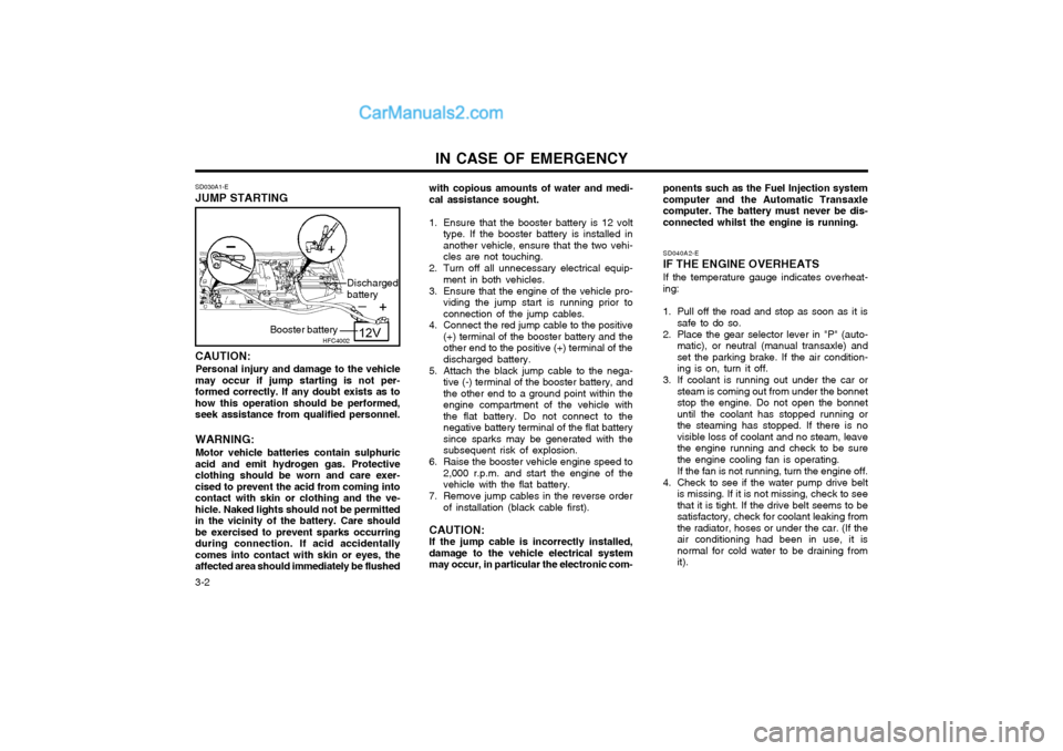
SD030A1-E JUMP STARTING
with copious amounts of water and medi- cal assistance sought.
1. Ensure that the booster battery is 12 volt type. If the booster battery is installed inanother vehicle, ensure that the two vehi-cles are not touching.
2. Turn off all unnecessary electrical equip- ment in both vehicles.
3. Ensure that the engine of the vehicle pro- viding the jump start is running prior toconnection of the jump cables.
4. Connect the red jump cable to the positive (+) terminal of the booster battery and theother end to the positive (+) terminal of thedischarged battery.
5. Attach the black jump cable to the nega- tive (-) terminal of the booster battery, andthe other end to a ground point within theengine compartment of the vehicle withthe flat battery. Do not connect to thenegative battery terminal of the flat batterysince sparks may be generated with thesubsequent risk of explosion.
6. Raise the booster vehicle engine speed to 2,000 r.p.m. and start the engine of thevehicle with the flat battery.
7. Remove jump cables in the reverse order of installation (black cable first).
CAUTION:If the jump cable is incorrectly installed,damage to the vehicle electrical systemmay occur, in particular the electronic com-
HFC4002
Booster battery Discharged battery
Page 260 of 312
3-3
IN CASE OF EMERGENCY
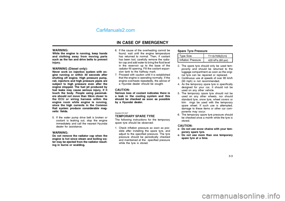
WARNING: While the engine is running, keep hands
and clothing away from moving parts such as the fan and drive belts to preventinjury.
WARNING (Diesel only): Never work on injection system with en-
gine running or within 30 seconds after shutting off engine. High pressure pump,rail, injectors and high pressure pipes aresubject to high pressure even after theengine stopped. The fuel jet produced byfuel leaks may cause serious injury, if ittouch the body. People using pacemak-ers should not move than 30cm closer tothe ECU or wiring harness within theengine room while engine is running,since the high currents in the CommonRail system produce considerable mag-netic fields.
5. If the water pump drive belt is broken or coolant is leaking out, stop the engine immediately and call the nearest Hyundaidealer for assistance.
WARNING: Do not remove the radiator cap when the
engine is hot since steam and boiling wa- ter may be ejected from the radiator result-ing in burns or scalding. D040A01FC-EAT TEMPORARY SPARE TYREThe following instructions for the temporary spare tyre should be observed:
1. Check inflation pressure as soon as pos-
sible after installing the spare tyre, and adjust to the specified pressure. The tyrepressure should be periodically checkedand maintained at the specified pressurewhile the tyre is stored. 2. The spare tyre should only be used tem-
porarily and should be returned to theluggage compartment as soon as the origi-nal tyre can be repaired or replaced.
3. Continuous use at speeds of over 80 km/h (50 mph) is not recommended.
4. As the temporary spare tyre is specifically designed for your car, it should not beused on any other vehicle.
5. The temporary spare tyre should not be used on any other wheels, nor shouldstandard tyre, snow tyre, wheel covers ortrim rings be used with the temporaryspare wheel. If such use is attempted,damage to these items or other car com-ponents may occur.
6. The temporary spare tyre pressure should be checked once a month while the tyre isstored.
CAUTION:
o Do not use snow chains with your tem- porary spare tyre.
o Do not use more than one temporary spare tyre at a time.
Spare Tyre Pressure
Type Size Inflation Pressure T115/70R(D)15420 kPa (60 psi)6. If the cause of the overheating cannot be
found, wait until the engine temperature has returned to normal. Then, if coolanthas been lost, carefully remove the radia-tor cap and add water to bring the fluid levelin the reservoir up to the base of theradiator fill opening. Fill the coolant expan-sion tank to the halfway mark.
7. Proceed with caution until it is established that the engine is operating normally. If theengine overheats repeatedly, the advice ofa Hyundai dealer should be sought.
CAUTION: Serious loss of coolant indicates there is a leak in the cooling system and thisshould be checked as soon as possibleby a Hyundai dealer.
Page 271 of 312

VEHICLE MAINTENANCE REQUIREMENTS
5- 4 F030C01E-EAT
R : REPLACE I : INSPECT AND, AFTER INSPECTION, CLEAN, ADJUST, REPAIR OR REPLACE IF NECESSARY
GENERAL MAINTENANCE COOLING SYSTEMCOOLANT GASOLINE ENGINEDIESEL ENGINE
ENGINE COOLANT SPECIFIC GRAVITYMANUAL TRANSAXLE OILAUTOMATIC TRANSAXLE FLUIDBRAKE PIPES, HOSES, AND CONNECTIONSBRAKE FLUIDCLUTCH FLUIDREAR BRAKE LININGS AND CYLINDERSBRAKE PADSSUSPENSION AND STEERING SYSTEMFRONT SUSPENSION BALL JOINTSPOLLEN FILTER (IN FRONT OF BLOWER UNIT)REAR WHEEL BEARINGSTYRE CONDITION AND PRESSURE (incl. Spare)LUBRICATE LOCKS AND HINGESCHECK ALL ELECTRICAL SYSTEMSROAD TESTCHECK ALL SYSTEMS WITH HI-SCAN
60 72
50 60
4048
I
R R
I I
R I
R R I I II
R
IIIII I
I I IIII I I I I
R I III I I
I
R IIII
R R I I I I
R I III I I
30 36
2024
I
R
I IIII I I II
R IIIIII
I
R IIII
R R I I I I
R I III I I
10 12
I I IIII I I I I
R I III I I
MILES X 1,000 MONTHS
NO. DESCRIPTION
1 2 3 456789
10111213141516171819
Page 274 of 312
VEHICLE MAINTENANCE REQUIREMENTS 5-7
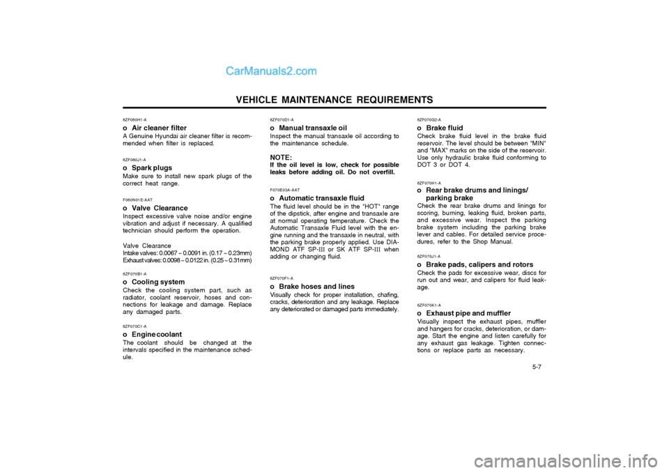
6ZF070D1-A
o Manual transaxle oil Inspect the manual transaxle oil according to
the maintenance schedule. NOTE: If the oil level is low, check for possible
leaks before adding oil. Do not overfill.
6ZF070H1-A
o Rear brake drums and linings/ parking brake
Check the rear brake drums and linings for
scoring, burning, leaking fluid, broken parts, and excessive wear. Inspect the parkingbrake system including the parking brakelever and cables. For detailed service proce-dures, refer to the Shop Manual.
6ZF070J1-A
o Brake pads, calipers and rotors Check the pads for excessive wear, discs for
run out and wear, and calipers for fluid leak-age.
6ZF070K1-A
o Exhaust pipe and muffler Visually inspect the exhaust pipes, mufflerand hangers for cracks, deterioration, or dam-age. Start the engine and listen carefully forany exhaust gas leakage. Tighten connec-tions or replace parts as necessary.
F070E03A-AAT
o Automatic transaxle fluid The fluid level should be in the "HOT" range
of the dipstick, after engine and transaxle areat normal operating temperature. Check theAutomatic Transaxle Fluid level with the en-gine running and the transaxle in neutral, withthe parking brake properly applied. Use DIA-MOND ATF SP- III or SK ATF SP- III when
adding or changing fluid. 6ZF070F1-A
o Brake hoses and lines Visually check for proper installation, chafing, cracks, deterioration and any leakage. Replaceany deteriorated or damaged parts immediately.
6ZF060H1-A
o Air cleaner filter A Genuine Hyundai air cleaner filter is recom-
mended when filter is replaced.
6ZF060J1-A
o Spark plugs Make sure to install new spark plugs of the
correct heat range.
6ZF070B1-A
o Cooling system Check the cooling system part, such asradiator, coolant reservoir, hoses and con-nections for leakage and damage. Replaceany damaged parts. 6ZF070G2-A
o Brake fluid Check brake fluid level in the brake fluidreservoir. The level should be between "MIN"and "MAX" marks on the side of the reservoir.Use only hydraulic brake fluid conforming toDOT 3 or DOT 4.
6ZF070C1-A
o Engine coolant The coolant should be changed at theintervals specified in the maintenance sched-ule.
F060N01E-AAT
o Valve Clearance Inspect excessive valve noise and/or enginevibration and adjust if necessary. A qualifiedtechnician should perform the operation.
Valve Clearance
Intake valves: 0.0067 ~ 0.0091 in. (0.17 ~ 0.23mm)
Exhaust valves: 0.0098 ~ 0.0122 in. (0.25 ~ 0.31mm)