stop start Hyundai Matrix 2003 Owner's Guide
[x] Cancel search | Manufacturer: HYUNDAI, Model Year: 2003, Model line: Matrix, Model: Hyundai Matrix 2003Pages: 312, PDF Size: 4.1 MB
Page 163 of 312
7-2EMISSION CONTROL SYSTEMS
H020B01A-GAT
About the Catalytic Converter
Exhaust gases passing through the catalytic
converter cause it to operate at very high tem- peratures. As a result, the introduction of largeamounts of unburned gasoline may cause it tooverheat and create a fire hazard. This can beavoided by observing the following:
o Use unleaded fuel only.
o Maintain your engine in good condition. Ex- tremely high converter temperatures can result from improper operation of the electri-cal, ignition or fuel injection systems.
o If your engine stalls, pings, knocks, or is hard to start, take your car to your Hyundaidealer as soon as possible and have thedifficulty corrected.
o Avoid driving with a very low fuel level. If your run out of gasoline, it could cause theengine to misfire and result in excessiveloading of the catalytic converter.
o Avoid idling the engine for periods longer than 10 minutes.
o Your Hyundai should not be either pushed or pulled to get it started. This can cause thecatalytic converter to overload.
o Take care not to stop your Hyundai over any combustible material such as grass, paper,leaves or rags. As these materials couldcome in contact with the catalytic converterand could cause a fire. o Do not touch the catalytic converter or any
other part of the exhaust system while theengine is running as it is very hot and couldresult in burns.
o Remember that your Hyundai dealer is your best source of assistance.
H020D01S-GAT
CATALYTIC CONVERTER ; For a diesel engine
All Hyundai vehicles are equipped with oxida- tion type catalytic converter to reduce the car-bon monoxide, hydrocarbons and particulatecontained in the exhaust gas.
H020C01S-GAT
EGR SYSTEM ; For a diesel engine
This system helps control oxides of nitrogen by recirculating a part of the exhaust gas into theengine.
Page 171 of 312
INDEX
10-2 Driving
Economical dr iving ........................................................................ 2-10
Smooth cornering .......................................................................... 2-10
Winter driving ................................................................................ 2-10
E Emissions Control Systems ................................................................ 7-1
Engine Before starting the engine ............................................................... 2-2Compartment .......................................................................... 6-1 ~ 6-3
Coolant ................................................................................. 6-8 ~ 6-10
Coolant temperature gauge ........................................................... 1-35
If the engine overheats ................................................................... 3-2
Number ............................................................................................ 8-1
Oil ........................................................................................... 6-4 ~ 6-5Starting ............................................................................................ 2-3
Engine Exhaust Can Be Dangerous ................................................... 2-1
FFold-up Tray ...................................................................................... 1-49
Front Fog Light Sw itch ...................................................................... 1-41
Front Seats Adjustable front seats ..................................................................... 1-9
Lumbar support control ................................................................. 1-10
Seat cushion height adjustment .................................................... 1-10
Fuel Capacity .......................................................................................... 9-1
Gauge ............................................................................................ 1-35
Recommendations ........................................................................... 1-1
Fuel Filler Lid
Remote release ............................................................................. 1-51
Fuse Panel Description .......................................................... 6-26 ~ 6-28
Fuses ...................................................................................... 6-19 ~6-20 GGeneral Checks
.................................................................................. 6-4
Glove box .......................................................................................... 1-46
H Hazard Warning System ................................................................... 1-40
Headlight Aiming Adjustment ........................................................... 6-23
Headlight Bulb ................................................................................... 6-23
Headlight Leveling Device System ........................................ 1-43 ~ 1-44
Heating and Ventilation
Air flow control .............................................................................. 1-57
Air intake control ........................................................................... 1-56
Bi-level heating .............................................................................. 1-58
Fan speed control ......................................................................... 1-56
Heating controls ............................................................................ 1-58
Temperature control ...................................................................... 1-58
High-mounted Rear Stoplight ............................................................ 1-49
Hood Release ................................................................................... 1-50
Horn .................................................................................................. 1-54
IIgnition Switch ..................................................................................... 2-2
Immobilizer System ............................................................................. 1-3
Instrument Cluster and Indicator ............................................ 1-30 ~ 1-34
Instruments and Controls .................................................................. 1-29
Interior Light Interior light ................................................................................... 1-46
Map light ........................................................................................ 1-45
Intermittent Wiper .............................................................................. 1-40
JJump Starting ...................................................................................... 3-1
Page 182 of 312
1- 1
CONTROLS AND EQUIPMENTfrom jerry cans or by means of a funnel that the fuel being used is unleaded. The use of leaded fuel in this vehicle will result in irreversible pollution of the catalyst ele-ment. Such pollution will prevent correct op-eration of the catalyst and give rise to in-creased operating temperatures leading tothe catalyst element melting and restrictingthe exhaust flow along with an increase inexhaust emission levels. CAUTION: The vehicle warranty will not extend to damage arising from the use of incorrectfuels. Use Diesel Diesel fuel of 52 to 54 cetane is used in Hyundai vehicle. If two types of diesel fuel areavailable, use summer or winter fuel properlyaccording to the following temperature condi-tions.
o Above 23°F (-5°C) ... Summer type diesel fuel.
o Below 23°F (-5°C) ... Winter type diesel fuel. Watch the fuel level in the tank very carefully : If the engine stops through fuel failure, thecircuits must be completely purged to permitrestarting.
SB000A1-E
1. CONTROLS AND
EQUIPMENT
B010A02O-EAT FUEL RECOMMENDATIONS THIS VEHICLE MUST ONLY BE OPERATED WITH UNLEADED FUEL. SERIOUS DAMAGE WILL RESULT FROM THE USE OF LEADED FUEL.
UNLEADED FUEL ONLY
Unleaded fuel with a Research Octane Num- ber (RON) of 91 or higher must be used in thisvehicle. To prevent accidental charging of the fuel tank with leaded fuel, a small diameter fillerneck along with a restrictor flap are fitted toensure that only unleaded fuel pump nozzlesmay enter the filler neck. However, care mustbe exercised when charging the vehicle tank SB010E1-A GASOLINES FOR CLEANER AIR To help contribute to cleaner air, Hyundai recommends that you use gasolines treatedwith detergent additives, which help to pre-vent deposit formation in the engine. Thesegasolines will help the engines run cleanerand the Emission Control System performance.
CAUTION: Do not let any gasoline or water enter the tank. This would make it necessary todrain it out and to bleed the lines to avoidjamming the injection pump and damagingthe engine. Overseas Operation: When the vehicle is to be operated overseas, the vehicle operator should establish that asuitable fuel for satisfactory operation of thevehicle is available.
1
B010A01FC
Page 210 of 312

1- 29
CONTROLS AND EQUIPMENTSB210E1-E OVERDRIVE OFF INDICATOR LIGHT (Not all models)
When the overdrive (4th gear) switch is turned off and the operation of overdrive (4th gear) iscancelled, the overdrive warning light (O/DOFF) will be illuminated. When the switch is atthe on position, the gearbox will operate in thenormal fully automatic mode and the warninglight will be extinguished.
B260P02Y-EAT
ABS SERVICE REMINDER INDICATOR (SRI)(Not all models)
When the key is turned to the "ON" position, the Anti-Lock Brake System SRI will come onand then go off in a few seconds. If the ABSSRI remains on, comes on while driving, ordoes not come on when the key is turned tothe "ON" position, this indicates that theremay be a problem with the ABS. If this occurs, have your vehicle checked by your Hyundai dealer as soon as possible. Thenormal braking system will still be operational,but without the assistance of the anti-lockbrake system.
CAUTION: If the both ABS SRI and Parking Brake/
Brake fluid level warning lights remain "ON" or come on while driving, there may be a
problem with E.B.D (Electronic Brake Force
Distribution).
If this occurs, avoid sudden stops and
have your vehicle checked by your Hyundaidealer as soon as possible. SB210K1-E
OIL PRESSURE WARNING LIGHT
CAUTION: If the oil pressure light illuminates when the engine is running, an insufficient oilpressure level for continued safe opera-tion of the engine exists. Continued opera-tion of the engine in this condition mayresult in serious engine damage. Under normal circumstances, the light will illuminate when the ignition is turned "on" andwill be extinguished when the engine is started. If the oil pressure warning light illuminates whilst the engine is running, stop the engineimmediately and check the engine oil level. Ifthe level is insufficient, add the required amountof oil as indicated by the engine oil dipstick. Ifthe light fails to extinguish when the engine isrestarted, do not continue to operate the ve-hicle. If the oil pressure light illuminates during nor- mal operation and the cause is not an insuffi-cient oil level, or the light fails to illuminatewhen the ignition is turned "on", contact thenearest Hyundai dealer before further operat-ing the vehicle.
SB210G1-E TURN SIGNAL INDICATOR LIGHT
Operation of a turn signal is indicated by the warning light located in the instrument cluster.If the light fails to illuminate or does not flash,a malfunction within the turn signal system isindicated.
SB210J1-E HIGH BEAM INDICATOR LIGHT
The high beam indicator light will illuminate
whenever the headlights are switched to high beam of flash position.
SB210C1-F
SRS (Airbag) SERVICE REMINDER INDICATOR
The SRS service reminder indicator (SRI) comes on and flashes for about 6 secondsafter the ignition key is turned to the "ON"position or after the engine is started, afterwhich it will go out. This light also comes on when the SRS is not working properly. If the SRI does not come on, or continuously remains on after flashing for about 6 secondswhen you turned the ignition key to the "ON"position or started the engine, or if it comes onwhile driving, have the SRS inspected by anauthorized Hyundai Dealer.
Page 211 of 312
CONTROLS AND EQUIPMENT
1- 30 circuits becoming defective, approximately fifty per cent of the normal braking perfor-mance will be available.
If failure of one of the circuits occurs, the
required amount of pedal effort, pedal traveland stopping distance will be increased. Useof the gearbox is recommended to assist inbringing the vehicle to rest. The vehicle mustnot be driven once brake failure has occurreduntil the system has been repaired and isfunctioning normally.
The braking system employs a vacuum servo
in order that the pedal efforts are reduced.Power for the servo is derived from the engineand therefore, in the event of the enginestopping or the vehicle being towed, pedalefforts will be substantially increased.
SB210L2-E
PARKING BRAKE/BRAKE FLUID LEVEL WARNING LIGHT
WARNING: In the event of problems being suspected with the braking system, the advice of thenearest Hyundai dealer must be soughtbefore the vehicle is driven. Driving thevehicle with either an electrical or hydrau-lic braking system defect may be danger-ous, resulting in accident or personal in-jury. Warning light operation The parking brake/brake fluid level warning light will be illuminated whenever the ignitionswitch is turned to the "ON" position irrespec-tive of whether or not the parking brake isapplied and must be extinguished when theengine starts and the parking brake released. If the warning light fails to extinguish or illumi- nates at any other time, the vehicle must bebrought to rest in a safe location and the levelof brake fluid in the reservoir checked. If thefluid level is incorrect, fluid conforming to DOT3 or DOT 4 specifications should be added. If,after correcting the brake fluid level, the warn-ing light continues to be illuminated, the ad-vice of the nearest Hyundai dealer must besought before the vehicle is driven again.The Hyundai Matrix is equipped with a diago-nally split dual braking system which will en-sure that in the event of one of the brake
CAUTION: If the drive belt (generator belt) is loosen,
broken, or missing while the vehicle is driving, there may be a serious malfunc-tion, engine could overheat because thisbelt also drives the water pump.
SB210M1-E CHARGING SYSTEM WARNING LIGHT
The charging system warning light should
illuminate when the ignition switch is turned to the "ON" position and should be extinguishedwhen the engine is started. If the light fails toilluminate when the ignition is turned "ON" orfails to extinguish after starting the engine, thenearest Hyundai dealer should be contacted.If the light illuminates whilst the vehicle isbeing driven, stop the vehicle as soon as it issafe to do so and check the condition of thegenerator drive belt. If the belt is in place andthe tension is satisfactory, the advice of aHyundai dealer should be sought.
B260B01FC-EAT
TAIL GATE OPEN WARNING LIGHT
The tail gate warning light indicates when the
tail gate is open or is not fully closed. Ensure that the light has extinguished prior to drivingthe vehicle.
SB2100I-E DOOR AJAR WARNING LIGHT
The door ajar warning light indicates that a
door is not correctly closed. Ensure that the light is extinguished prior to driving the vehicle.
SB210P1-E
LOW FUEL LEVEL WARNING LIGHT
The low fuel warning light serves to warn the
driver that the remaining fuel quantity is ap- proximately 9 litres and that the vehicle shouldbe refuelled. If the vehicle is driven for anextended period with the low fuel warning lightilluminated there exists a possibility that mis-firing due to fuel shortage may occur. Thissituation must be avoided to prevent damageto the catalyst occurring.
Page 246 of 312
DRIVING YOUR HYUNDAI
2- 4 C050B02S-GAT
NORMAL CONDITIONS The Starting Procedure:
1. Insert key, and fasten the seat belt.
2. Depress the clutch pedal fully and place the gearshift lever (manual transaxle) in neutral or the selector lever (automatictransaxle) in "P" (park) position.
3. After turning the ignition key to the "ON" position, make certain all warning lightsand gauges are functioning properly be-fore starting the engine.
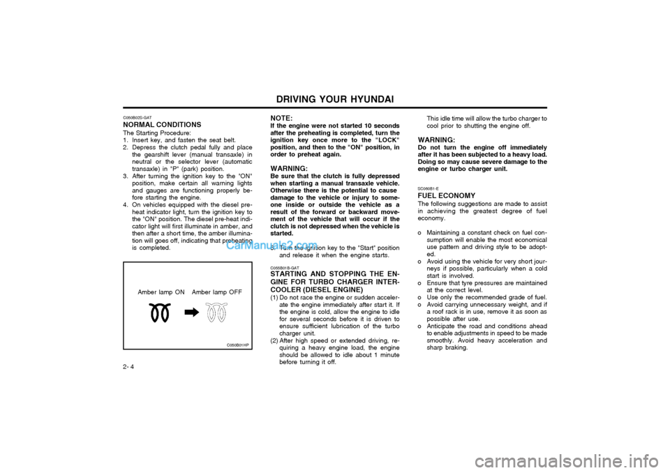
4. On vehicles equipped with the diesel pre- heat indicator light, turn the ignition key tothe "ON" position. The diesel pre-heat indi-cator light will first illuminate in amber, andthen after a short time, the amber illumina-tion will goes off, indicating that preheatingis completed. SC060B1-E FUEL ECONOMY
The following suggestions are made to assist in achieving the greatest degree of fueleconomy.
o Maintaining a constant check on fuel con- sumption will enable the most economicaluse pattern and driving style to be adopt-ed.
o Avoid using the vehicle for very short jour- neys if possible, particularly when a coldstart is involved.
o Ensure that tyre pressures are maintained at the correct level.
o Use only the recommended grade of fuel.
o Avoid carrying unnecessary weight, and if a roof rack is in use, remove it as soon aspossible after use.
o Anticipate the road and conditions ahead to enable adjustments in speed to be madesmoothly. Avoid heavy acceleration andsharp braking.
NOTE: If the engine were not started 10 seconds
after the preheating is completed, turn the ignition key once more to the "LOCK"position, and then to the "ON" position, inorder to preheat again.
WARNING: Be sure that the clutch is fully depressed
when starting a manual transaxle vehicle. Otherwise there is the potential to cause damage to the vehicle or injury to some-
one inside or outside the vehicle as aresult of the forward or backward move-ment of the vehicle that will occur if theclutch is not depressed when the vehicle isstarted.
5. Turn the ignition key to the "Start" position and release it when the engine starts.
C055B01B-GAT
STARTING AND STOPPING THE EN- GINE FOR TURBO CHARGER INTER- COOLER (DIESEL ENGINE)
(1) Do not race the engine or sudden acceler-
ate the engine immediately after start it. If the engine is cold, allow the engine to idlefor several seconds before it is driven toensure sufficient lubrication of the turbocharger unit.
(2) After high speed or extended driving, re- quiring a heavy engine load, the engineshould be allowed to idle about 1 minutebefore turning it off. This idle time will allow the turbo charger tocool prior to shutting the engine off.
WARNING: Do not turn the engine off immediately after it has been subjected to a heavy load.Doing so may cause severe damage to theengine or turbo charger unit.
C050B01HP
Amber lamp ON Amber lamp OFF
Page 247 of 312

DRIVING YOUR HYUNDAI 2- 5
SC090A02-E
MANUAL TRANSAXLE
HFC3029
The five speed fully synchronized transaxle is controlled by a floor mounted shift lever uponwhich the shift pattern is indicated. It is impor-tant that when changing gear, the clutch pedalis fully depressed to avoid transaxle damage. CAUTION:
o Do not attempt to engage reverse gear
when the car is in motion.
o To avoid damaging the selector mecha- nism, do not use the gear shift lever as a hand rest. Release the lever immedi-ately the shift is completed.
o To avoid premature clutch wear, do not use the clutch pedal as a foot rest, anddo not hold the vehicle on a gradientusing the clutch.
o Ensure that the engine is not over-revved by upshifting before the tachometerneedle enters the red zone.
o Do not coast with the shift lever at the neutral position.
o When descending long gradients, make use of the engine braking to assist thefootbrake to avoid brake fade or over-heating.
o When slippery conditions are encoun- tered, increased caution should be ex-ercised when gear changing, braking oraccelerating. Abrupt changes in speedmay cause a loss of traction or controlof the vehicle.
o The starter motor will not operate un- less the clutch pedal is depressed whilstthe engine is being started.
o During cold weather, shifting may be difficult until the transaxle lubricant haswarmed up. This is normal and notharmful to the transaxle. SC090B1-F
Using the Clutch The clutch should be pressed all the way to
the floor before shifting, then released slowly.Do not rest your foot on the clutch pedal whiledriving.
This can cause unnecessary wear. Do not partially engage the clutch to hold the
car on an incline. This causes unnecessary wear.
Use the parking brake to hold the car on an
incline. Do not operate the clutch pedal rapidlyand repeatedly.
o Avoid cruising at unnecessary high speeds.
o Always ensure that the periodic mainte-
nance services are performed by a Hyundai dealer at the time and/or mileage intervalsspecified.
o Use the air conditioning only when neces- sary.
o If you 've come to a complete stop and it's hard to shift into 1 st
or R(Reverse),
put the shift lever in N(Neutral) position and release the clutch. Press the clutchpedal back down, and then shift into 1 st
or R(Reverse) gear position.
o Do not use the shift lever as a handrest during driving, as this can result inpremature wear of the transaxle shiftforks.
Page 250 of 312

DRIVING YOUR HYUNDAI
2- 8 o Always engage the parking brake when
the vehicle is unattended, never use the "P" position in place of the parking brake.
o Under normal circumstances, the selector should be placed in the "D" position andthe transaxle allowed to select the mostideal ratio for the circumstances. In thisposition maximum fuel economy will beachieved.
o When descending steep gradients where engine braking is required, the selectorshould be placed at the "2" or "L" positiondepending upon the vehicle speed.
o When ascending steep gradients using large throttle openings, the transaxle mayre-peatedly change between two adjacentratios. This is a normal characteristic andmay be prevented by cancelling the over-drive facility if the shifting occurs betweenthird and fourth ratios, selecting position"2" if the shifting occurs between third andsecond ratios or selecting position "1" if theshifting occurs between first and secondratios.
o Never move the selector to or from the "P" or "N" position with the accelerator de-pressed.
o Ensure that the overdrive switch is at the "ON" position for maximum economy. o If rapid acceleration is required, fully de-
press the accelerator pedal. In this condi-tion, the kickdown mechanism will be oper-ated and the transaxle will automaticallydownshift according to the vehicle speed.
o The automatic transaxle may be used to great effect if the vehicle becomes stuck insnow or mud by allowing the vehicle to berocked to and fro. The engine speed shouldbe held at approximately 1,000rpm bymeans of the accelerator pedal and theselector lever moved between the "D" and"R" positions to induce a rocking motion.
o Do not depress the accelerator pedal with the brakes applied and the selector at the"R", "D", "2" or "L" position.
o Turn the overdrive switch on for good fuel economy and smooth driving. But if enginebraking is needed in the "D" range or ifrepeated upshifting and downshifting be-tween the 3rd and 4th gear is neededwhen climbing a gentle slope, it is recom-mended that the overdrive switch be turnedoff. Turn the overdrive switch back onimmediately afterward.
C090I02A-EAT
CAUTION:
o Shift into "R" and "P" only when the vehicle has completely stopped.
o Do not accelerate the engine in reverse or any of the forward positions with the brakes applied.
o Always apply the footbrake when shift- ing from "P" or "N", to "R", "D", "2" or"L" position.
o Do not use the "P" (Park) position in place of the parking brake. Always setthe parking brake, shift the transaxleinto "P" (Park) and turn off the ignitionwhen you leave the vehicle, even mo-mentarily. Never leave the vehicle unat-tended whilst the engine is running.
o Check the automatic transaxle fluid level regularly, and add fluid as necessary. See the maintenance schedule for the proper fluid recommendation.
FC120D1-E
General Operating Instructions
o The button in the selector handle must be depressed before the selector can be moved.
o The engine may only be started when the selector is at position "P" or "N".
o Ensure that the footbrake is firmly applied when shifting from "P" or "N" to "D", "2", "L"or "R" and vice versa.
Page 251 of 312

DRIVING YOUR HYUNDAI 2- 9
SC130A1-E
OVERDRIVE SWITCH
The overdrive switch prevents the transaxle
upshifting higher than third gear when the switch is turned "OFF". The transaxle will startfrom rest in first gear and upshift to secondand third gear depending upon the roadspeedand throttle opening but will not upshift tofourth gear. When the overdrive switch isturned "ON", the transaxle will start from restin first gear and will upshift, depending uponroadspeed and throttle opening to second,third and fourth gear. Therefore, when theoverdrive switch is turned "OFF", the transaxleperforms as a three speed unit and the over-drive warning light located in the instrumentcluster will be illuminated. When the overdriveswitch is turned "ON", the transaxle functionsas a fully automatic four speed unit with themaximum fuel economy potential of the ve-hicle being realized. o Do not hold the vehicle on the upgrade
with the accelerator pedal. This can causethe transmission to overheat. Always usethe brake pedal or parking brake.
SC140A1-E EFFECTIVE BRAKING Braking system performance and friction ma- terial life are greatly affected by the drivingstyle adopted. The following suggestions aremade to assist in achieving the best resultsfrom the braking system.
o Anticipate the road and conditions ahead
in order that heavy braking may be avoided.
o When descending long gradients, use the engine to assist in retarding the vehicle to minimize the possibility of brake fade oc-curring.
o When trailer towing, ensure that the trailer brakes function correctly and use enginebraking to assist the vehicle braking system.
o Use only genuine Hyundai replacement brake pads and shoes to ensure consis-tent friction characteristics and wear rates.
o After driving through deep water (e.g. fording), the brakes may become wet andperformance reduced. Always check brakeefficiency after emerging from the waterand dry the brakes by lightly depressingthe brake pedal several times whilst driv-ing slowly.
o Apply the parking brake only when the vehicle is at rest.
o Since the power assistance provided by the brake servo is derived from the engine,coasting with the engine turned off or tow-ing of the vehicle with the engine turned offwill result in greatly increased pedal pres-sures being required to stop the vehicle. SC140B1-E
ANTI-LOCK BRAKE SYSTEM (Not all models)
The Anti-Lock Brake System (ABS) is de-
signed to prevent wheel lock-up during sud- den braking or on hazardous road surfaces.The ABS control module monitors the wheelspeed and controls the pressure applied toeach brake. Thus, in emergency situations oron slick roads, ABS will increase vehicle con-trol during braking.
NOTE: During ABS operation, a slight pulsation
may be felt in the brake pedal when the brakes are applied. Also, a noise may beheard in the engine compartment whilstbraking. These conditions are normal andindicate that the anti-lock brake system isfunctioning properly.
WARNING:ABS will not prevent accidents due to im-
proper or dangerous driving maneuvers.Even though vehicle control is improvedduring emergency braking, always maintaina safe distance between you and objectsahead. Vehicle speeds should always bereduced during extreme road conditions.
HFC3023-D
Page 252 of 312

DRIVING YOUR HYUNDAI
2- 10 C300B01O-GAT
TCS ON Mode In the TCS ON mode, the indicator in the instrument cluster will not be illuminated. NOTE:
1) Turn off the engine. Then restart the engine, and the TCS mode will auto- matically turn "ON".
2) When the traction control is operating properly, you can feel a slight pulsationin the vehicle. This is only the effect ofbrake control and indicates nothingunusual. C300D02O-GAT
Indicator and Warning
The indicator should illuminate when the igni-tion key is turned to "ON" or "START", butshould go out after three seconds. If the indicator does not illuminate, have it checked by an authorized Hyundai dealer. Should there be any unusual conditions in the device, TCS illuminates as a warning.If TCS illuminates, pull your car to a safeplace and stop the engine. Then, start the engine again to check if the TCS indicator goes out. If the indicator remains lit even after the engine has been started, have your carchecked by an authorized Hyundai dealer. NOTE: When TCS illuminates, traction control is automatically deactivated for safety.
Driving hints
TCS does not actively apply brakes. Be sure
to decelerate the car sufficiently before enter-ing curves.
CAUTION: When the TCS indicator blinks, SLIP con-
trol has been activated. It also means that the road is slippery or your car is acceler-ating excessively. In this situation, releasefoot pressure from the accelerator pedaland maintain moderate speed.
WARNING: Traction control is only a driving aid; all
normal precautions for driving in inclem- ent weather and on slippery driving sur-faces should be observed. 3) When the engine starts, a click is heard
from the engine compartment; however,this is only the sound of traction controlbeing checked.
4) When moving out of the mud or fresh snow, pressing the accelerator pedalmay not cause the engine speed toincrease.
The braking distance for cars equippedwith an anti-lock braking system may belonger than for those without it in thefollowing road conditions.
o Driving on rough, gravel or snow-cov-
ered roads.
o Driving with tyre chains installed.
o Driving on roads where the road sur- face is pitted or has different surface height.
These roads should be driven at reducedspeeds. The safety features of an ABSequipped vehicle should not be tested byhigh speed driving or cornering. This couldendanger the safety of yourself or others.
C300A01O-EAT
BRAKE TRACTION CONTROL SYSTEM (BTCS) (Not all models)
On slippery road surfaces, the traction control
system (TCS) limits the drive wheels from spinning excessively, thus helping the car toaccelerate. It also provides sufficient drivingforce and steering performance as the carturns at accelerated speeds. SLIP Control
Limits the drive wheels from spinning exces-
sively during starting or while making acceler- ated turns on slippery roads to avoid losingthe driving force of the front wheels.