tension Hyundai Matrix 2003 Owner's Manual
[x] Cancel search | Manufacturer: HYUNDAI, Model Year: 2003, Model line: Matrix, Model: Hyundai Matrix 2003Pages: 312, PDF Size: 4.1 MB
Page 30 of 312
FEATURES OF YOUR HYUNDAI
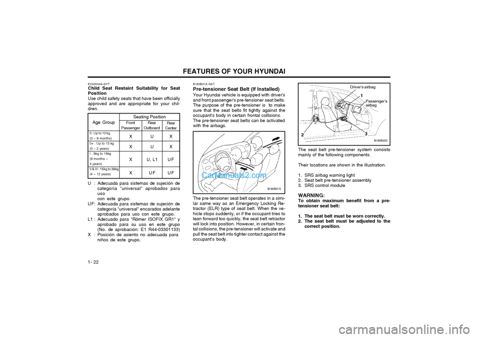
1- 22 B180B01A-GAT Pre-tensioner Seat Belt (If Installed)Your Hyundai vehicle is equipped with driver's and front passenger's pre-tensioner seat belts.The purpose of the pre-tensioner is to makesure that the seat belts fit tightly against theoccupant's body in certain frontal collisions.The pre-tensioner seat belts can be activatedwith the airbags.
B180B01S
B180B02S
Driver's airbag
1
2
3
Passenger's airbag
The seat belt pre-tensioner system consists mainly of the following components. Their locations are shown in the illustration.
1. SRS airbag warning light
2. Seat belt pre-tensioner assembly
3. SRS control module WARNING: To obtain maximum benefit from a pre-tensioner seat belt:
1. The seat belt must be worn correctly.
2. The seat belt must be adjusted to the correct position.
The pre-tensioner seat belt operates in a simi-lar same way as an Emergency Locking Re-tractor (ELR) type of seat belt. When the ve-hicle stops suddenly, or if the occupant tries tolean forward too quickly, the seat belt retractorwill lock into position. However, in certain fron-tal collisions, the pre-tensioner will activate andpull the seat belt into tighter contact against theoccupant's body.
Age Group
Seating PositionFront
Passenger Rear
Outboard Rear
Center
0 : Up to 10 kg (0 ~ 9 months)0+ : Up to 13 kg(0 ~ 2 years)I : 9kg to 18kg(9 months ~4 years)II & III : 15kg to 36kg(4 ~ 12 years)XUX
XUX
X U, L1 U F XU FUF
E230H04A-GYT Child Seat Restaint Suitability for Seat Position
Use child safety seats that have been officiallyapproved and are appropriate for your chil-dren.
U : Adecuada para sistemas de sujeción de categoría "universal" aprobados parauso con este grupo.
U F: Adecuada para sistemas de sujeción de categoría "universal" encarados adelante aprobados para uso con este grupo.
L1 : Adecuado para "Römer ISOFIX GR1" y aprobado para su uso en este grupo(No. de aprobación: E1 R44-03301133)
X : Posición de asiento no adecuada para niños de este grupo.
Page 31 of 312
FEATURES OF YOUR HYUNDAI 1- 23
CAUTION:
o Because the sensor that activates the
SRS airbag is connected with the pre-tensioner seat belt, the SRS airbag warn-ing light on the instrument panel willblink for approximately 6 seconds afterthe ignition key has been turned to the"ON" position, and then it should turnoff.
o If the pre-tensioner seat belt is not work- ing properly, this warning light will illu-minate even if there is no malfunction ofthe SRS airbag system . If the SRS airbagwarning light does not illuminate whenthe ignition key is turned to "ON", or if itremains illuminated after blinking forapproximately 6 seconds, or if it illumi-nates while the vehicle is being driven,please have an authorized Hyundai deal-er inspect the pre-tensioner seat belt orSRS airbag system as soon as possible. WARNING:
o Pre-tensioners are designed to operate
only one time. After activation, pre-tensioner seat belts must be replaced.All seat belts, of any type, should alwaysbe replaced after they have been wornduring a collision.
o The pre-tensioner seat belt assembly mechanisms become hot during activa-tion. Do not touch the pre-tensioner seatbelt assemblies for several minutes afterthey have been activated.
o Do not attempt to inspect or replace the pre-tensioner seat belts yourself. Thismust be done by an authorized Hyundaidealer.
o Do not strike the pre-tensioner seat belt assemblies.
o Do not attempt to service or repair the pre-tensioner seat belt system in anymanner.
o Improper handling of the pre-tensioner seat belt assemblies, and failure to heedthe warnings to not strike, modify, in-spect, replace, service or repair the pre-tensioner seat belt assemblies may leadto improper operation or inadvertent ac-tivation and serious injury.
o Always wear the seat belts when driving or riding in a motor vehicle.
NOTE:
o Both the driver's and front passenger's pre-tensioner seat belts will be activatedin certain frontal collisions. The pre-tensioner seat belts can be activatedwith the airbags. The pre-tensioners willbe activated under these conditions evenif the seat belts are not being worn at thetime of the collision.
o When the pre-tensioner seat belts are activated, a loud noise may be heard andfine dust, which may appear to be smoke,may be visible in the passenger compart-ment. These are normal operating condi-tions and are not hazardous.
o Although it is harmless, the fine dust may cause skin irritation and should notbe breathed for prolonged periods. Washyour hands and face thoroughly after anaccident in which the pre-tensioner seatbelts were activated.
Page 41 of 312
FEATURES OF YOUR HYUNDAI 1- 33
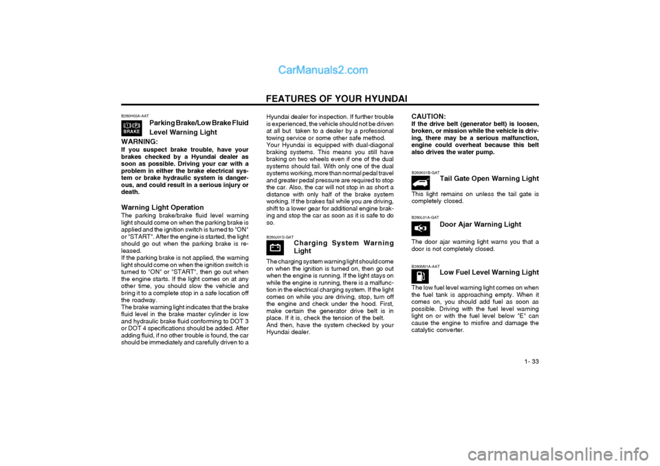
B260J01S-GAT
Charging System Warning Light
The charging system warning light should come on when the ignition is turned on, then go outwhen the engine is running. If the light stays onwhile the engine is running, there is a malfunc-tion in the electrical charging system. If the lightcomes on while you are driving, stop, turn offthe engine and check under the hood. First,make certain the generator drive belt is inplace. If it is, check the tension of the belt.And then, have the system checked by yourHyundai dealer.
CAUTION: If the drive belt (generator belt) is loosen,broken, or mission while the vehicle is driv-ing, there may be a serious malfunction,engine could overheat because this beltalso drives the water pump. B260L01A-GAT Door Ajar Warning Light
The door ajar warning light warns you that a door is not completely closed.B260H03A-AAT Parking Brake/Low Brake Fluid Level Warning Light
WARNING: If you suspect brake trouble, have your brakes checked by a Hyundai dealer assoon as possible. Driving your car with aproblem in either the brake electrical sys-tem or brake hydraulic system is danger-ous, and could result in a serious injury ordeath. Warning Light Operation The parking brake/brake fluid level warning light should come on when the parking brake isapplied and the ignition switch is turned to "ON"or "START". After the engine is started, the lightshould go out when the parking brake is re-leased.If the parking brake is not applied, the warninglight should come on when the ignition switch isturned to "ON" or "START", then go out whenthe engine starts. If the light comes on at anyother time, you should slow the vehicle andbring it to a complete stop in a safe location offthe roadway.The brake warning light indicates that the brakefluid level in the brake master cylinder is lowand hydraulic brake fluid conforming to DOT 3or DOT 4 specifications should be added. Afteradding fluid, if no other trouble is found, the carshould be immediately and carefully driven to a Hyundai dealer for inspection. If further troubleis experienced, the vehicle should not be drivenat all but taken to a dealer by a professionaltowing service or some other safe method.Your Hyundai is equipped with dual-diagonalbraking systems. This means you still havebraking on two wheels even if one of the dualsystems should fail. With only one of the dualsystems working, more than normal pedal traveland greater pedal pressure are required to stopthe car. Also, the car will not stop in as short adistance with only half of the brake systemworking. If the brakes fail while you are driving,shift to a lower gear for additional engine brak-ing and stop the car as soon as it is safe to doso.
B260K01B-GAT
Tail Gate Open Warning Light
This light remains on unless the tail gate is completely closed.
B260M01A-AAT Low Fuel Level Warning Light
The low fuel level warning light comes on whenthe fuel tank is approaching empty. When itcomes on, you should add fuel as soon aspossible. Driving with the fuel level warninglight on or with the fuel level below "E" cancause the engine to misfire and damage thecatalytic converter.
Page 118 of 312

WHAT TO DO IN AN EMERGENCY 3-7
STA3071H
WARNING: Wheel and wheel covers may have sharp edges. Handle them carefully to avoid pos- sible severe injury. Before putting the wheel into place, be sure that there is nothing on the hub or wheel (such as mud, tar, gravel, etc.) that interferes with the wheel from fitting solidly against the hub. If there is, remove it. If there is not good contact on the mounting surface between the wheel and hub, the wheel nuts could loosen and cause the loss of a wheel. Loss of a wheel may result in loss of control of the vehicle. This may cause serious injury or death. D060H02A-AAT 7. Re-install Wheel Nuts To reinstall the wheel cover, hold it on the studs, put the wheel nuts on the studs and tighten them finger tight. The nuts should be installed with their small diameter ends directed inward. Jiggle the tire to be sure it is completely seated, then tighten the nuts as much as possible with your fingers again.
Lower the car to the ground by turning the wheel nut wrench counterclockwise. Then position the wrench as shown in the drawing and tighten the wheel nuts. Be sure the socket is seated com- pletely over the nut. Do not stand on the wrench handle or use an extension pipe over the wrench handle. Go around the wheel tightening every other nut until they are all tight. Then double-check each nut for tightness. After changing wheels, have a technician tighten the wheel nuts to their proper torque as soon as possible. Wheel nut tightening torque: Steel wheel & aluminium alloy wheel: 900-1,100 kg.cm (65-80 lb.ft)
D060H01FCD060I01E-GAT 8. Lower Vehicle and Tighten NutsD060I01FC
Page 131 of 312
VEHICLE MAINTENANCE REQUIREMENTS
5- 6
F060A01A-AAT EXPLANATION OF SCHEDULED MAINTENANCE ITEMS F060M01A-AAT o Engine Oil and FilterThe engine oil and filter should be changed at
the intervals specified in the maintenance sched- ule. If the car is being driven in severe condi- tions, more frequent oil and filter changes are required. F060B01A-AAT
o Drive BeltsInspect all drive belts for evidence of cuts, cracks, excessive wear or oil saturation and replace if necessary. Drive belts should be checked periodically for proper tension andadjusted as necessary. F060C01A-AAT
o Fuel FilterA clogged filter can limit the speed at which the vehicle may be driven, damage the emission system and cause hard starting. If an exces- sive amount of foreign matter accumulates in the fuel tank, the filter may require replacement more frequently. After installing a new filter, run the engine for several minutes, and check for leaks at the connections. Fuel filters should be installed by trained technicians.
F060D02A-AAT
o Fuel Lines, Fuel Hoses and
Connections
Check the fuel lines, fuel hoses and connec- tions for leakage and damage. Have a trained technician replace any damaged or leaking parts immediately. WARNING (Diesel only): Never work on injection system with engine running or within 30 seconds after shutting off engine. High pressure pump, rail, injec- tors and high pressure pipes are subject to high pressure even after the engine stopped. The fuel jet produced by fuel leaks may cause serious injury, if it touch the body. People using pacemakers should not move than 30cm closer to the ECU or wiring har- ness within the engine room while engine is running, since the high currents in the Com- mon Rail system produce considerable mag- netic fields. F060E01A-AAT
o Timing BeltInspect all parts related to the timing belt for damage and deformation. Replace any dam- aged parts immediately. F060G01A-AAT
o Vapor Hose and Fuel Filler Cap The vapor hose and fuel filler cap should be
inspected at those intervals specified in themaintenance schedule. Make sure that a new vapor hose or fuel filler cap is correctly re- placed.
F060F01A-AAT
o Vacuum, Crankcase Ventilation
Hoses
Inspect the surface of hoses for evidence of
heat and/or mechanical damage. Hard and brit-tle rubber, cracking, tears, cuts, abrasions, and excessive swelling indicate deterioration. Par- ticular attention should be paid to examining those hose surfaces nearest to high heat sourc- es, such as the exhaust manifold.
Inspect the hose routing to assure that the
hoses do not come in contact with any heatsource, sharp edges or moving component which might cause heat damage or mechanical wear. Inspect all hose connections, such as clamps and couplings, to make sure they are secure, and that no leaks are present. Hoses should be replaced immediately if there is any evidence of deterioration or damage.
Page 133 of 312
VEHICLE MAINTENANCE REQUIREMENTS
5- 8 F070L01A-AAT
o Suspension Mounting Bolts Check the suspension connections for loose-
ness or damage. Retighten to the specified torque. F070M01A-AAT
o Steering Gear Box, Linkage & Boots/
Lower arm Ball Joint
With the vehicle stopped and engine off, check for excessive free-play in the steering wheel. Check the linkage for bends or damage. Check the dust boots and ball joints for deterioration, cracks, or damage. Replace any damaged parts. F070N01A-AAT o
Power Steering Pump, Belt and HosesCheck the power steering pump and hoses for leakage and damage. Replace any damaged or leaking parts immediately. Inspect the power steering belt for evidence of cuts, cracks, ex- cessive wear, oiliness and proper tension. Re- place or adjust it if necessary. F070P01A-AAT o Driveshafts and Boots Check the drive shafts, boots and clamps for cracks, deterioration, or damage. Replace any damaged parts and, if necessary, repack the grease. F070Q01A-AAT
o Air Conditioning Refrigerant Check the air conditioning lines and connec- tions for leakage and damage. Check air condi- tioning performance according to the relevant shop manual if necessary.
Page 150 of 312

DO-IT-YOURSELF MAINTENANCE 6-17
G160A01A-GAT
CHECKING CLUTCH PEDAL FREE-PLAY With the engine off, press lightly on the clutch pedal until you feel a change in resistance. Thisis the clutch pedal freeplay. The freeplay shouldbe within the limits specified in the illustration. Ifit is not, have it inspected by your Hyundaidealer and adjusted or repaired if necessary.
G160A01E
6 ~ 13 mm (0.24 ~ 0.51 in.)
G150A01A-GAT
CHECKING STEERING WHEEL FREEPLAY
To check the steering wheel freeplay, stop the
car with the wheels pointed straight ahead and gently move the steering wheel back and forth.Use very light finger pressure and be sensitiveto changes in resistance that mark the limits ofthe freeplay. If the freeplay is greater thanspecified, have it inspected by your Hyundaidealer and adjusted or repaired if necessary.
G150A01FC
G140D01S-GAT
Checking the Compressor Drive Belt
When the air conditioning is being used regular-
ly, the compressor drive belt tension should be checked at least once a month.
To check the drive belt tension, press down on
the belt halfway between the engine crankshaftand compressor pulleys. Pressing with yourfinger, you should not be able to deflect this beltanymore than 8.0 mm. If you have the instru-ments to check it with a force of 98N (22 lb.),the deflection should be approx. 8.0 mm (0.315in.). If the belt is too loose, have it adjusted byyour Hyundai dealer.
G140D01A
A/C
CRANK PULLEY
TENSION PULLEY
30 mm (1.18 in.)
8mm(0.315 in.)
Page 151 of 312

DO-IT-YOURSELF MAINTENANCE
6-18 G190A01A-GAT CHECKING DRIVE BELTS (Gasoline Engine) Drive belts should be checked periodically for proper tension and adjusted if necessary. At thesame time, belts should be examined for cracks,wear, fraying or other evidence of deteriorationand replaced if necessary. Belt routing should also be checked to be sure there is no interference between the belts andother parts of the engine. After a belt is re-placed, the new belt should be adjusted againafter two or three weeks to eliminate slackresulting from initial stretching after use.
SSA6190A
Water Pump Pulley
Alternator Pulley
Crankshaft Pulley 5.1~6 mm (0.2~0.24 in.)
G180A01A-GAT
CHECKING BRAKE PEDAL CLEARANCE
You need a helper to check the brake pedal
clearance. With the engine running, have your helper press down on the brake pedal severaltimes and then hold it down with a force of about490N (50 kg, 110 lbs). The brake pedal clear-ance is the distance from the top surface of thebrake pedal to the asphalt sheeting under thefloor mat. If the brake pedal clearance is notwithin the limits specified in the illustration, haveit inspected by your Hyundai dealer and adjust-ed or repaired if necessary.
SSA6180A
45.1 mm (1.78 in.)
G170A01A-GAT
CHECKING BRAKE PEDAL FREE-PLAY
With the engine off, press down on the brake
pedal several times to reduce the vacuum in the brake booster.
Then, using your hand, press down slowly on
the brake pedal until you feel a change inresistance. This is the brake pedal freeplay.The freeplay should be within the limits speci-fied in the illustration. If it is not, have it inspect-ed by your Hyundai dealer and adjusted orrepaired if necessary.
SSA6170A
3 ~ 8 mm (0.12 ~ 0.31 in.)
Page 172 of 312
INDEX10-3
R
Rear Fog Audible Warning Sound
....................................................1-35
Rear Seat Adjustable headrests ..................................................................... 1-11
Adjusting seatback angle .............................................................. 1-11
Adjusting seat forward and rearward ............................................ 1-11
Arm Rest ....................................................................................... 1-43
Fold down ........................................................................... 1-12 ~ 1-13
Rear Window Defroster Switch ......................................................... 1-41
Recommended Shift Poi nts ................................................................ 2-5
Removal of water from the fuel fiter ................................................. 6-22
Replacing Light Bulbs ....................................................................... 6-22
Replacing The Spark Plugs .............................................................. 6-10
Roof R ack ......................................................................................... 1-53
SSeat Belts 2-Point Static Type ............................................................ 1-16 ~ 1-173-Point system ................................................................... 1-15 ~ 1-16
Adjustable height ........................................................................... 1-15
Adjusting your seat belt ................................................................ 1-16
Care of seat belts ......................................................................... 1-14
Precautions ................................................................................... 1-13
Seat Warmer ..................................................................................... 1-13
Spark Plugs ........................................................................... 6-10 ~ 6-11
Spectacle Case ................................................................................. 1-46
Speedometer ..................................................................................... 1-35
Starting Procedures ............................................................................ 2-3Steering Wheel Free play ....................................................................................... 6-17
Tilt lever ........................................................................................ 1-54
Stereo Radio Operation (H210, H220, H260, H280) ............................ 1-64 ~ 1-65, 1-66 ~ 1-67, 1-70 ~ 1-72, 1-77 ~ 1-79
Stereo Sound System ............................................................ 1-62 ~ 1-63
K
Keys .................................................................................................... 1-2
If you lose your keys .................................................................... 3-10
Positions .......................................................................................... 2-2
LLight Bulb Replacement ......................................................... 6-22 ~ 6-23
Lubrication Chart ................................................................................. 9-3
Luggaga Net ..................................................................................... 1-52
M Maintenance Intervals Explanation of scheduled maintenance items ........................ 5-7 ~ 5-8
Maintenance under severe usage conditions ................................. 5-6
Scheduled maintenance ......................................................... 5-3 ~ 5-5
Service requirements ...................................................................... 5-1
Mirros Day-night inside rearview .............................................................. 1-48
Outside rear view .......................................................................... 1-47
Multi Box ........................................................................................... 1-47
O Odometer .......................................................................................... 1-36
Outside Rearview Mirror Heater ....................................................... 1-48
PParking Brake ................................................................................... 1-49
Power Outlet ..................................................................................... 1-50
Power Steering Fluid Level .............................................................. 6-21
Pre-tensioner Seat Belt .......................................................... 1-22 ~ 1-23
Page 200 of 312
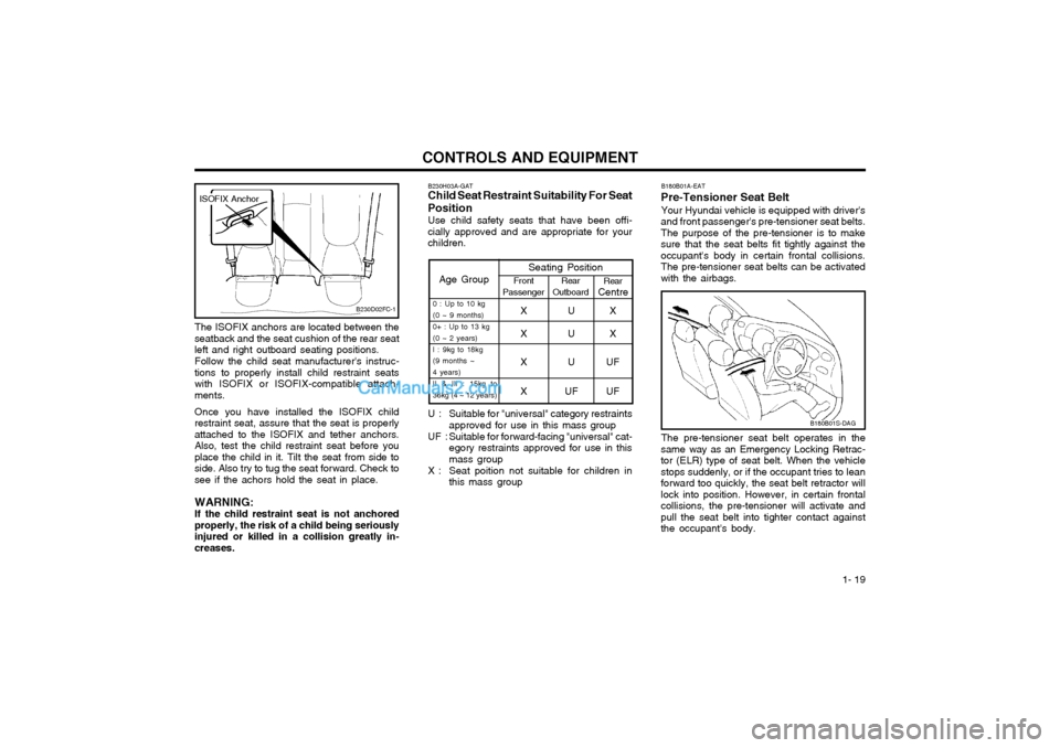
1- 19
CONTROLS AND EQUIPMENT
Age GroupSeating PositionFront
Passenger Rear
Outboard Rear
Centre
0 : Up to 10 kg (0 ~ 9 months)0+ : Up to 13 kg(0 ~ 2 years)I : 9kg to 18kg (9 months ~ 4 years)II & III : 15kg to 36kg (4 ~ 12 years)XUX
XUX
XUU F
XU FUF
The ISOFIX anchors are located between the
seatback and the seat cushion of the rear seat left and right outboard seating positions.
Follow the child seat manufacturer's instruc-
tions to properly install child restraint seatswith ISOFIX or ISOFIX-compatible attach-ments.
Once you have installed the ISOFIX child
restraint seat, assure that the seat is properlyattached to the ISOFIX and tether anchors.Also, test the child restraint seat before youplace the child in it. Tilt the seat from side toside. Also try to tug the seat forward. Check tosee if the achors hold the seat in place.
WARNING:If the child restraint seat is not anchored
properly, the risk of a child being seriouslyinjured or killed in a collision greatly in-creases.
B230D02FC-1
ISOFIX Anchor
B180B01S-DAG
B180B01A-EAT
Pre-Tensioner Seat Belt
Your Hyundai vehicle is equipped with driver's
and front passenger's pre-tensioner seat belts. The purpose of the pre-tensioner is to makesure that the seat belts fit tightly against theoccupant's body in certain frontal collisions.The pre-tensioner seat belts can be activatedwith the airbags.
The pre-tensioner seat belt operates in the
same way as an Emergency Locking Retrac- tor (ELR) type of seat belt. When the vehiclestops suddenly, or if the occupant tries to leanforward too quickly, the seat belt retractor willlock into position. However, in certain frontalcollisions, the pre-tensioner will activate andpull the seat belt into tighter contact againstthe occupant's body.
B230H03A-GAT Child Seat Restraint Suitability For Seat Position Use child safety seats that have been offi- cially approved and are appropriate for yourchildren.
U : Suitable for "universal" category restraints approved for use in this mass group
UF : Suitable for forward-facing "universal" cat- egory restraints approved for use in this mass group
X : Seat poition not suitable for children in this mass group