Hyundai Matrix 2004 Owner's Manual
Manufacturer: HYUNDAI, Model Year: 2004, Model line: Matrix, Model: Hyundai Matrix 2004Pages: 317, PDF Size: 5.12 MB
Page 261 of 317
IN CASE OF EMERGENCY
3-2
CAUTION: Personal injury and damage to the vehicle may occur if jump starting is not per- formed correctly. If any doubt exists as to how this operation should be performed, seek assistance from qualified personnel. WARNING: Motor vehicle batteries contain sulphuric acid and emit hydrogen gas. Protective clothing should be worn and care exer- cised to prevent the acid from coming into contact with skin or clothing and the ve- hicle. Naked lights should not be permitted in the vicinity of the battery. Care should be exercised to prevent sparks occurring during connection. If acid accidentally comes into contact with skin or eyes, the affected area should immediately be flushed CAUTION: If the jump cable is incorrectly installed,
damage to the vehicle electrical system may occur, in particular the electronic components such as the Fuel Injection system computer and the Automatic
Transaxle computer. The battery must never be disconnected whilst the engine is running. SD040A2-E IF THE ENGINE OVERHEATS
If the temperature gauge indicates overheat- ing:
1. Pull off the road and stop as soon as it is safe to do so.
2. Place the gear selector lever in "P" (auto- matic), or neutral (manual transaxle) and set the parking brake. If the air condition- ing is on, turn it off.
3. If coolant is running out under the car or
steam is coming out from under the bonnet stop the engine. Do not open the bonnet until the coolant has stopped running or the steaming has stopped. If there is no visible loss of coolant and no steam, leave the engine running and check to be sure the engine cooling fan is operating.If the fan is not running, turn the engine off.
4. Check to see if the water pump drive belt is missing. If it is not missing, check to seethat it is tight. If the drive belt seems to be
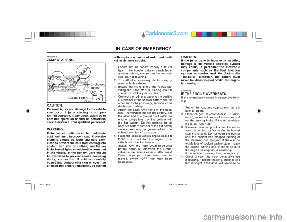
SD030A2-E JUMP STARTING
with copious amounts of water and medi- cal assistance sought.
1. Ensure that the booster battery is 12 volt
type. If the booster battery is installed in another vehicle, ensure that the two vehi- cles are not touching.
2. Turn off all unnecessary electrical equip- ment in both vehicles.
3. Ensure that the engine of the vehicle pro- viding the jump start is running prior to connection of the jump cables.
4. Connect the red jump cable to the positive (+) terminal of the booster battery and theother end to the positive (+) terminal of the discharged battery.
5. Attach the black jump cable to the nega- tive (-) terminal of the booster battery, andthe other end to a ground point within the engine compartment of the vehicle with the flat battery. Do not connect to the negative battery terminal of the flat battery since sparks may be generated with the subsequent risk of explosion.
6. Raise the booster vehicle engine speed to 2,000 r.p.m. and start the engine of thevehicle with the flat battery.
7. Switch "ON" the main beam headlamps before carefully removing the jumper cables in the reverse order of attachment. Once the jumper cables have been re- moved, switch "OFF" the main beam headlamps.
HFC4002
Booster battery Discharged battery
fcuk-3.p65
3/6/2007, 9:59 AM
2
Page 262 of 317
3-3
IN CASE OF EMERGENCY
satisfactory, check for coolant leaking from the radiator, hoses or under the car. (If the air conditioning had been in use, it is normal for cold water to be draining from it).
WARNING: While the engine is running, keep hands and clothing away from moving parts such as the fan and drive belts to prevent injury. WARNING (Diesel only): Never work on injection system with en-gine running or within 30 seconds after shutting off engine. High pressure pump, rail, injectors and high pressure pipes are subject to high pressure even after the engine stopped. The fuel jet produced by fuel leaks may cause serious injury, if it touch the body. People using pacemak- ers should not move than 30cm closer to the ECU or wiring harness within the engine room while engine is running, since the high currents in the Common Rail system produce considerable mag- netic fields.
5. If the water pump drive belt is broken or coolant is leaking out, stop the engine immediately and call the nearest Hyundai dealer for assistance. WARNING:Do not remove the radiator cap when theengine is hot since steam and boiling water may be ejected from the radiator resulting in burns or scalding.
6. If the cause of the overheating cannot be found, wait until the engine temperature has returned to normal. Then, if coolant has been lost, carefully remove the radia- tor cap and add water to bring the fluid level in the reservoir up to the base of the radiator fill opening. Fill the coolant expan- sion tank to the halfway mark.
7. Proceed with caution until it is established that the engine is operating normally. If theengine overheats repeatedly, the advice of a Hyundai dealer should be sought.
CAUTION: Serious loss of coolant indicates there isa leak in the cooling system and this should be checked as soon as possible by a Hyundai dealer. D040A01FC-EAT
TEMPORARY SPARE TYRE The following instructions for the temporary
spare tyre should be observed:
1. Check inflation pressure as soon as pos-
sible after installing the spare tyre, and adjust to the specified pressure. The tyre pressure should be periodically checked and maintained at the specified pressure while the tyre is stored.
2. The spare tyre should only be used tem- porarily and should be returned to the luggage compartment as soon as the origi- nal tyre can be repaired or replaced.
3. Continuous use at speeds of over 80 km/h
(50 mph) is not recommended.
4. As the temporary spare tyre is specifically designed for your car, it should not beused on any other vehicle.
5. The temporary spare tyre should not be used on any other wheels, nor shouldstandard tyre, snow tyre, wheel covers or trim rings be used with the temporary spare wheel. If such use is attempted, damage to these items or other car com- ponents may occur.
6. The temporary spare tyre pressure should be checked once a month while the tyre isstored.
Spare Tyre Pressure
Type Size
Inflation Pressure T115/70R(D)15
420 kPa (60 psi)
fcuk-3.p65
3/6/2007, 9:59 AM
3
Page 263 of 317
IN CASE OF EMERGENCY
3-4
SD070A1-E
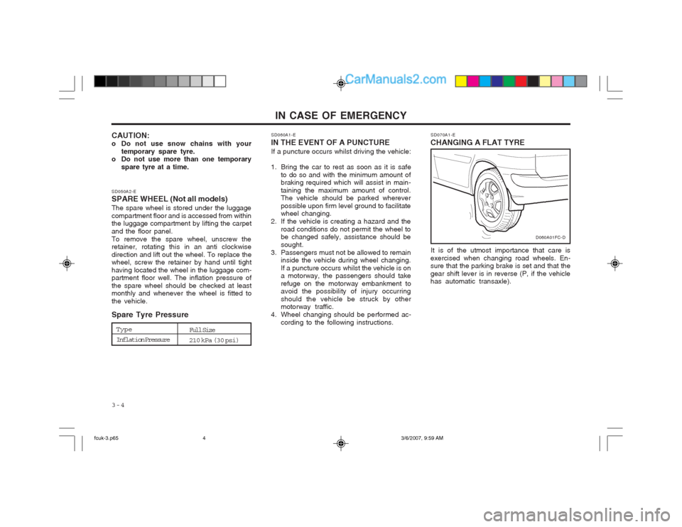
CHANGING A FLAT TYRE
It is of the utmost importance that care is
exercised when changing road wheels. En- sure that the parking brake is set and that the gear shift lever is in reverse (P, if the vehicle has automatic transaxle).
D060A01FC-D
SD050A2-E SPARE WHEEL (Not all models) The spare wheel is stored under the luggage compartment floor and is accessed from within the luggage compartment by lifting the carpet and the floor panel.To remove the spare wheel, unscrew the retainer, rotating this in an anti clockwise direction and lift out the wheel. To replace the wheel, screw the retainer by hand until tight having located the wheel in the luggage com- partment floor well. The inflation pressure of the spare wheel should be checked at least monthly and whenever the wheel is fitted to the vehicle. Spare Tyre Pressure
CAUTION:
o Do not use snow chains with your
temporary spare tyre.
o Do not use more than one temporary
spare tyre at a time. SD060A1-E
IN THE EVENT OF A PUNCTURE If a puncture occurs whilst driving the vehicle:
1. Bring the car to rest as soon as it is safe to do so and with the minimum amount of braking required which will assist in main- taining the maximum amount of control. The vehicle should be parked wherever possible upon firm level ground to facilitate wheel changing.
2. If the vehicle is creating a hazard and the road conditions do not permit the wheel tobe changed safely, assistance should be sought.
3. Passengers must not be allowed to remain inside the vehicle during wheel changing.If a puncture occurs whilst the vehicle is on a motorway, the passengers should take refuge on the motorway embankment to avoid the possibility of injury occurring should the vehicle be struck by other motorway traffic.
4. Wheel changing should be performed ac- cording to the following instructions.
Type
Inflation Pressure Full Size
210 kPa (30 psi)
fcuk-3.p65
3/6/2007, 9:59 AM
4
Page 264 of 317
3-5
IN CASE OF EMERGENCY
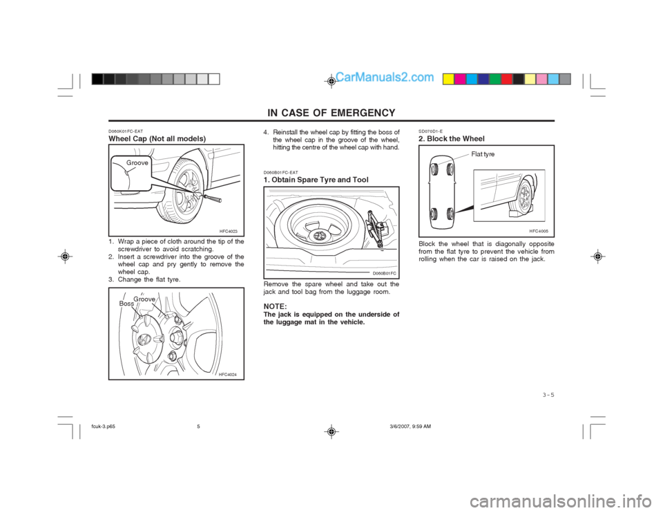
D060K01FC-EAT Wheel Cap (Not all models)
HFC4024
1. Wrap a piece of cloth around the tip of the
screwdriver to avoid scratching.
2. Insert a screwdriver into the groove of the wheel cap and pry gently to remove the wheel cap.
3. Change the flat tyre. HFC4023
Groove
BossGroove
Remove the spare wheel and take out the jack and tool bag from the luggage room. NOTE: The jack is equipped on the underside ofthe luggage mat in the vehicle.
D060B01FC-EAT 1. Obtain Spare Tyre and Tool
4. Reinstall the wheel cap by fitting the boss of
the wheel cap in the groove of the wheel,
hitting the centre of the wheel cap with hand.
D060B01FC Block the wheel that is diagonally opposite from the flat tyre to prevent the vehicle from rolling when the car is raised on the jack.
SD070D1-E 2. Block the Wheel
Flat tyre
HFC4005
fcuk-3.p65 3/6/2007, 9:59 AM
5
Page 265 of 317
IN CASE OF EMERGENCY
3-6 SD070G1-E
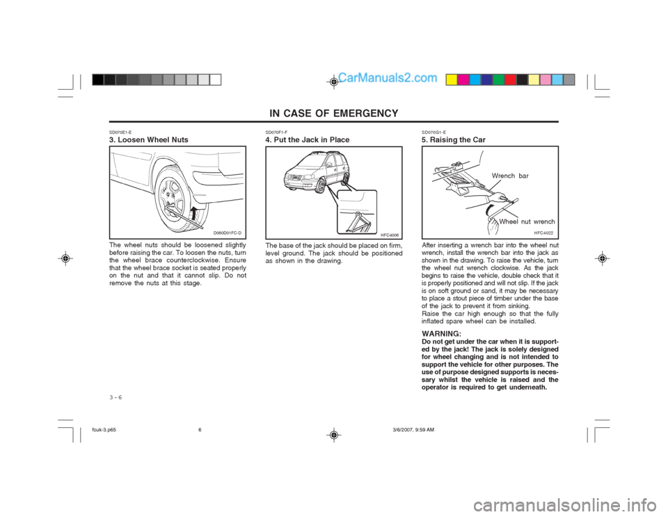
5. Raising the Car
After inserting a wrench bar into the wheel nut
wrench, install the wrench bar into the jack as shown in the drawing. To raise the vehicle, turn the wheel nut wrench clockwise. As the jack begins to raise the vehicle, double check that it is properly positioned and will not slip. If the jack is on soft ground or sand, it may be necessary to place a stout piece of timber under the base of the jack to prevent it from sinking.
Raise the car high enough so that the fully
inflated spare wheel can be installed.
WARNING: Do not get under the car when it is support-
ed by the jack! The jack is solely designedfor wheel changing and is not intended to support the vehicle for other purposes. The use of purpose designed supports is neces- sary whilst the vehicle is raised and the operator is required to get underneath.
HFC4022
Wrench bar
Wheel nut wrench
SD070E1-E 3. Loosen Wheel Nuts The wheel nuts should be loosened slightly before raising the car. To loosen the nuts, turn the wheel brace counterclockwise. Ensure that the wheel brace socket is seated properly on the nut and that it cannot slip. Do not remove the nuts at this stage. SD070F1-F
4. Put the Jack in Place
The base of the jack should be placed on firm,level ground. The jack should be positioned as shown in the drawing.
D060D01FC-DHFC4006
fcuk-3.p65 3/6/2007, 9:59 AM
6
Page 266 of 317
3-7
IN CASE OF EMERGENCY
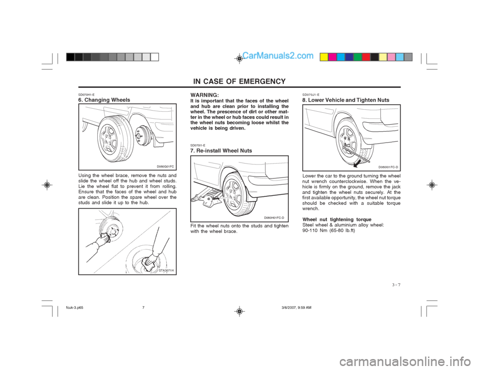
WARNING: It is important that the faces of the wheeland hub are clean prior to installing the wheel. The prescence of dirt or other mat- ter in the wheel or hub faces could result in the wheel nuts becoming loose whilst the vehicle is being driven. SD070I1-E
7. Re-install Wheel Nuts
Fit the wheel nuts onto the studs and tighten with the wheel brace.
SD070H1-E 6. Changing Wheels Using the wheel brace, remove the nuts and slide the wheel off the hub and wheel studs. Lie the wheel flat to prevent it from rolling. Ensure that the faces of the wheel and hub are clean. Position the spare wheel over the studs and slide it up to the hub.
STA3071H
D060H01FC-D
D060G01FC
SD070J1-E
8. Lower Vehicle and Tighten Nuts
Lower the car to the ground turning the wheel
nut wrench counterclockwise. When the ve- hicle is firmly on the ground, remove the jack and tighten the wheel nuts securely. At the first available opportunity, the wheel nut torque should be checked with a suitable torque wrench.
Wheel nut tightening torqueSteel wheel & aluminium alloy wheel: 90-110 Nm (65-80 lb.ft)
D060I01FC-D
fcuk-3.p65 3/6/2007, 9:59 AM
7
Page 267 of 317
IN CASE OF EMERGENCY
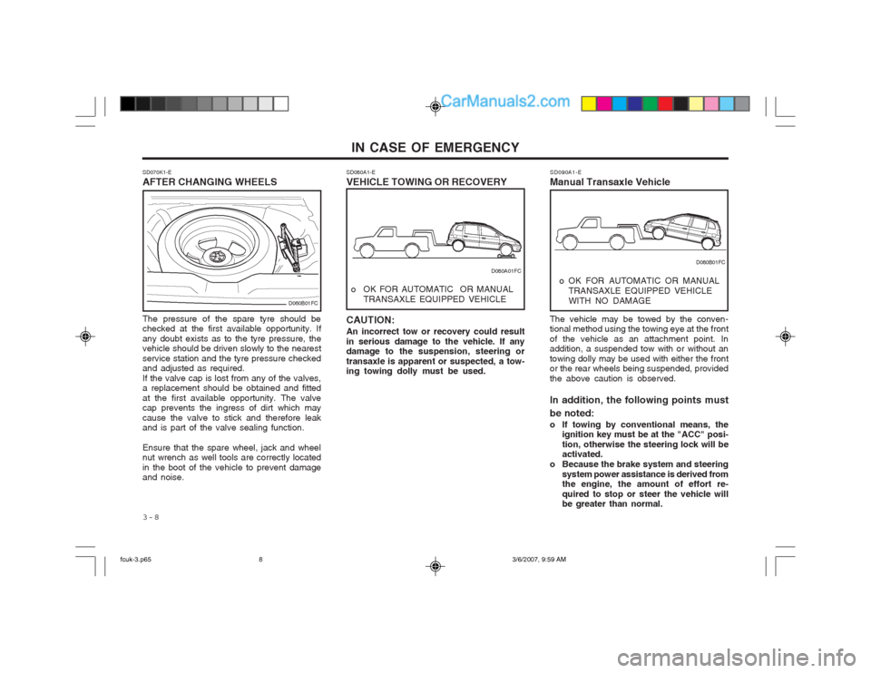
3-8 The vehicle may be towed by the conven- tional method using the towing eye at the front of the vehicle as an attachment point. In addition, a suspended tow with or without an towing dolly may be used with either the front or the rear wheels being suspended, provided the above caution is observed. In addition, the following points must be noted:
o If towing by conventional means, the
ignition key must be at the "ACC" posi- tion, otherwise the steering lock will be activated.
o Because the brake system and steering system power assistance is derived fromthe engine, the amount of effort re- quired to stop or steer the vehicle will be greater than normal.
SD090A1-E
Manual Transaxle Vehicle
o OK FOR AUTOMATIC OR MANUAL TRANSAXLE EQUIPPED VEHICLE WITH NO DAMAGE D080B01FC
SD070K1-E AFTER CHANGING WHEELS
SD080A1-EVEHICLE TOWING OR RECOVERY
The pressure of the spare tyre should be checked at the first available opportunity. If any doubt exists as to the tyre pressure, the vehicle should be driven slowly to the nearest service station and the tyre pressure checked and adjusted as required. If the valve cap is lost from any of the valves, a replacement should be obtained and fitted at the first available opportunity. The valve cap prevents the ingress of dirt which may cause the valve to stick and therefore leak and is part of the valve sealing function. Ensure that the spare wheel, jack and wheel nut wrench as well tools are correctly located in the boot of the vehicle to prevent damage and noise. CAUTION: An incorrect tow or recovery could result in serious damage to the vehicle. If any damage to the suspension, steering or transaxle is apparent or suspected, a tow- ing towing dolly must be used.
D060B01FC
o OK FOR AUTOMATIC OR MANUAL
TRANSAXLE EQUIPPED VEHICLE D080A01FC
fcuk-3.p65
3/6/2007, 9:59 AM
8
Page 268 of 317
3-9
IN CASE OF EMERGENCY
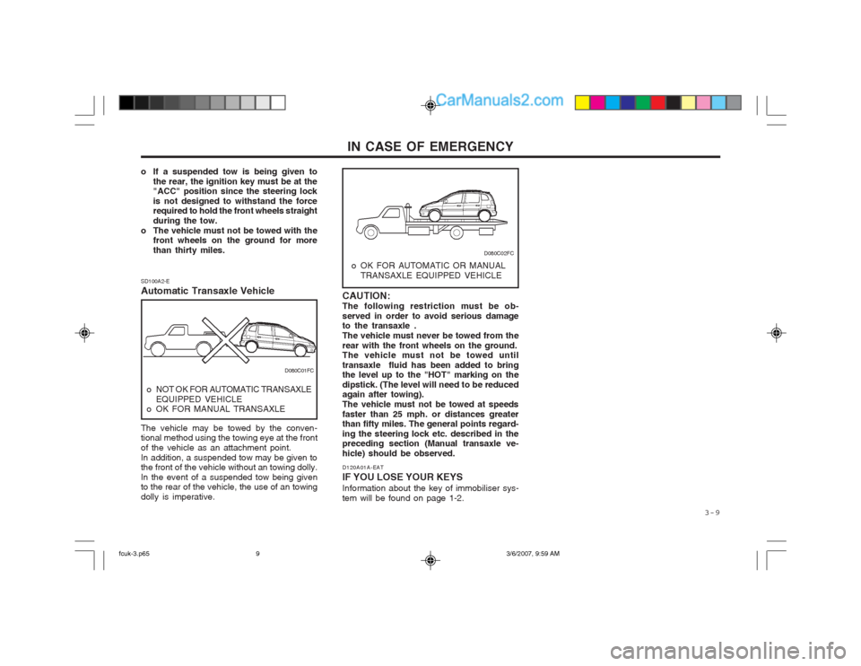
o If a suspended tow is being given to the rear, the ignition key must be at the "ACC" position since the steering lock is not designed to withstand the force required to hold the front wheels straight during the tow.
o The vehicle must not be towed with the front wheels on the ground for morethan thirty miles.
o OK FOR AUTOMATIC OR MANUAL
TRANSAXLE EQUIPPED VEHICLE
SD100A2-E Automatic Transaxle Vehicle
o NOT OK FOR AUTOMATIC TRANSAXLE
EQUIPPED VEHICLE
o OK FOR MANUAL TRANSAXLE
The vehicle may be towed by the conven- tional method using the towing eye at the front of the vehicle as an attachment point.In addition, a suspended tow may be given to the front of the vehicle without an towing dolly. In the event of a suspended tow being given to the rear of the vehicle, the use of an towing dolly is imperative. D120A01A-EAT IF YOU LOSE YOUR KEYS Information about the key of immobiliser sys- tem will be found on page 1-2.
CAUTION:The following restriction must be ob-served in order to avoid serious damage to the transaxle . The vehicle must never be towed from therear with the front wheels on the ground. The vehicle must not be towed until transaxle fluid has been added to bring the level up to the "HOT" marking on the dipstick. (The level will need to be reduced again after towing). The vehicle must not be towed at speedsfaster than 25 mph. or distances greater than fifty miles. The general points regard- ing the steering lock etc. described in the preceding section (Manual transaxle ve- hicle) should be observed.
D080C01FC
D080C02FC
fcuk-3.p65
3/6/2007, 9:59 AM
9
Page 269 of 317
APPEARANCE CARE 4-1
garding the retreatment programme must be observed in accordance with the Terms and Conditions outlined in the separate Anti Per- foration Warranty Booklet. NOTE: The underbody should never be steamcleaned since the underbody coating may be removed by this process. During the interim period between powerwashing the underbody, the more vulnera- ble areas such as wheel arches should be hosed off particularly during the winter sea- son to prevent prolonged contact with road salts.Ensure that the various drain points located at the bottom of the door panels and sills are kept clear to prevent water from becom- ing trapped within the cavities. Wherever possible, the parking of the vehicle in a confined, poorly ventilated location (a ga- rage for example) should be avoided when the vehicle is wet or is covered with snow or ice. Under these conditions, the internal cavities of the vehicle will remain damp for prolonged periods of time which will en- courage corrosion. Parking the vehicle where good ventilation exists (outside for example) is preferable.
SE040A1-E VALETING Regular cleaning of the exterior paintwork serves two important functions. Firstly, the removal of abrasive dirt and contaminants will maintain the lustre of the paintwork and will prevent discolouration and dulling due to prolonged con- tact. Secondly, the presence of damage through im- pact or abrasion will be apparent allowing early rectification to be made thus preventing corro- sion from becoming established and spreading beneath the paint film. To avoid "water spotting" the vehicle should not be washed in direct sun- light particularly in the case of vehicles having dark body colours. The heat from the sun rays is absorbed by the paint film increasing the surface temperature. This action causes water used for washing to evaporate quickly leaving behind the deposits from the water and the shampoo used. Use only a shampoo intended for the purpose and ensure that the body work is thoroughly wetted to soften the dirt film prior to attempting to remove this. After removing the dirt film with a soft sponge, the body work should be thoroughly rinsed and then dried with a good quality chamois leather to prevent streaking or spotting of the paint work. Household detergents, solvents and abrasive cleaning materials should not be used in order to avoid damaging the paint film.
SE030A1-E UNDERBODY COATINGSEvery Hyundai passenger car receives a full underbody and cavity injection treatment during production. In order that this treatment may retain maximum effectiveness it is recommend- ed that the underbody receives a power wash and a thorough inspection after each winter season. In doing so any accumulations of mud, which act as moisture traps and com- bine with road salts to accelerate corrosion will be removed. In order to maintain the Anti Perforation Warranty, the requirements re-
SE000A1-E
4. APPEARANCE
CARE
SE020A1-E PROTECTING YOUR HYUNDAI FROM CORROSION By using the most advanced design and con- struction practices, every Hyundai is built to retain the original factory finish for many years. However, long term durability is also greatly dependant upon maintaining the various protec- tion systems and coatings used in manufacture since constant, exposure to the elements will result in a breakdown and loss of effectiveness. The following suggestions are made to assist in the maintenance of the vehicle bodywork.
4
fcuk-4.p65 3/6/2007, 10:00 AM
1
Page 270 of 317
APPEARANCE CARE
4-2
Plastic wheel covers should be cleaned using a sponge and water. Cast alloy wheels should be cleaned using a mild soap or neutral deter- gent. Abrasive compounds must not be used since in the event of these damaging the lac- quer coating, oxidization of the aluminium wheel will occur, spoiling the appearance. The use of an a toothbrush will facilitate cleaning between the wheel "spokes".
ensure that accidental spillages are immediately flushed with water. Do not use abrasive cleaning materials which may damage the bumpers. Avoid subjecting the bumpers to high tempera- tures such as may be encountered in high bake paint ovens.
SE040B1-E STAIN/SPOT REMOVAL Should tree sap, dead insects or tar prove to be difficult to remove from the paint film, turpentine or a proprietary paint cutting compound may be used. Ensure that the area to be cleaned is not rubbed intensively to prevent breaking through the colour coat and exposing the under coat. SE040C1-E POLISHINGThe exterior paint work should be polished with a proprietary wax polish when water no longer collects in bead form on the paint work. The instructions of the product manufacturer should be adhered to. SE040E1-E BUMPER MAINTENANCEThe special material from which the bumpers are manufactured warrants special attention to pre- serve the appearance of the bumpers. Avoid contact with battery electrolyte or brake fluid and SE040F1-E ACCIDENT REPAIRSIn the event of the body work sustaining damage, the following points should be noted prior to repairs being undertaken. If body panels are replaced or repaired, anti corrosion treatment must be applied to the repair area. The product used must be compatible withthose used in manufacture. It is recommended that repairs are entrusted to a Hyundai dealer to ensure that replacement parts used are of the same high quality as those used in manufacture of the vehicle and that the correct repair methods and materials will ensure adequate levels of corrosion protection and the continued validity of the Anti Perforation Warranty. SE050A1-E INTERIORDuring the winter period, it is possible that the passenger compartment flooring may become wet from damp footwear or quantities of snow adhering to footwear. The carpet should not be allowed to remain in this condition since the carpet may begin to create musty smells and will
SE050D1-E SEAT BELTS Seat belts should be cleaned only with a mild soap solution. Strong detergents, solvens or bleaches may damage the belt webbing and therefore reduce the effectiveness of the belt. Belts which display signs of fraying, wear of cut should be replaced. SE050E1-E WINDOWS A proprietary glass cleaner should be used to clean the inside of the windows. However, the rear heated windshield must only be cleaned using a light horizontal cleaning action. Care should be exercised to avoid the use of abrasive cleaners or contact with items of jewellery which may damage the heating elements.
promote corrosion of the floor pan in addition tothe carpet and under felt beginning to rot. SE050C1-E INTERIOR VALETING The soft trim and carpets should be maintained with the regular use of a vacuum cleaner. Heavy soiling should be removed with a dry cleaning agent recommended for this purpose following the instructions of the product manufacturer. Paint thinner, solvents or other such cleaning materials should not be used since damage to the upholstery may result.
fcuk-4.p65
3/6/2007, 10:00 AM
2