fuse box Hyundai Matrix 2004 Owner's Manual
[x] Cancel search | Manufacturer: HYUNDAI, Model Year: 2004, Model line: Matrix, Model: Hyundai Matrix 2004Pages: 317, PDF Size: 5.12 MB
Page 35 of 317
FEATURES OF YOUR HYUNDAI 1- 27
parts. If the liquid from the air freshener does leak onto these areas, wash them withwater immediately. WARNING:
o When the SRS is activated, there may be
a loud noise and fine dust will be re-leased throughout the vehicle. These con-ditions are normal and are not hazard-ous. However, the fine dust generatedduring airbag deployment may causeskin irritation. Wash your hands and facethoroughly with lukewarm water and amild soap after an accident in which theairbags were deployed.
o The SRS can function only when the ignition key is in the "ON" position. If theSRS SRI does not come on, or continu-ously remains on, after flashing for about6 seconds when the ignition key is turnedto the "ON" position, or after the engineis started, comes on while driving, theSRS is not working properly. If this oc-curs, have your vehicle immediately in-spected by your Hyundai dealer.
o Before you replace a fuse or disconnect a battery terminal, turn the ignition key tothe "LOCK" position or remove the igni-tion key. Never remove or replace the airbag related fuse(s) when the ignition keyis in the "ON" position. Failure to heedthis warning will cause the SRS SRI toilluminate.
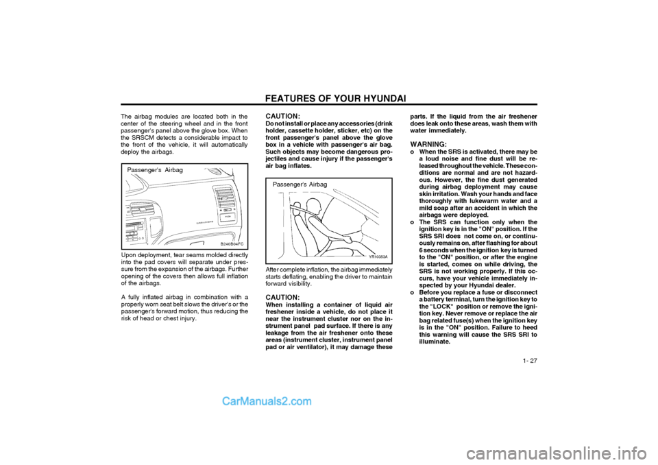
Passenger's Airbag
YR10353A
After complete inflation, the airbag immediately starts deflating, enabling the driver to maintainforward visibility. CAUTION: When installing a container of liquid airfreshener inside a vehicle, do not place itnear the instrument cluster nor on the in-strument panel pad surface. If there is anyleakage from the air freshener onto theseareas (instrument cluster, instrument panelpad or air ventilator), it may damage these
CAUTION:Do not install or place any accessories (drinkholder, cassette holder, sticker, etc) on thefront passenger's panel above the glovebox in a vehicle with passenger's air bag.Such objects may become dangerous pro-jectiles and cause injury if the passenger'sair bag inflates.
Passenger's Airbag
The airbag modules are located both in the center of the steering wheel and in the frontpassenger's panel above the glove box. Whenthe SRSCM detects a considerable impact tothe front of the vehicle, it will automaticallydeploy the airbags.
Upon deployment, tear seams molded directlyinto the pad covers will separate under pres-sure from the expansion of the airbags. Furtheropening of the covers then allows full inflationof the airbags. A fully inflated airbag in combination with a properly worn seat belt slows the driver's or thepassenger's forward motion, thus reducing therisk of head or chest injury.
B240B04FC
Page 56 of 317
FEATURES OF YOUR HYUNDAI
1- 48
B510D01E
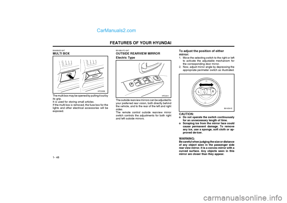
B510B01FC-GAT OUTSIDE REARVIEW MIRROR Electric Type
HFC2011
The outside rearview mirrors can be adjusted to your preferred rear vision, both directly behindthe vehicle, and to the rear of the left and rightsides.The remote control outside rearview mirrorswitch controls the adjustments for both rightand left outside mirrors.
HFC2058
The multi box may be opened by pulling it out by its grip.It is used for storing small articles.If the multi box is removed, the fuse box for thelights and other electrical accessories will beexposed.
B500B02E-GAT MULTI BOX
To adjust the position of either mirror:
1. Move the selecting switch to the right or left
to activate the adjustable mechanism for the corresponding door mirror.
2. Now, adjust mirror angle by depressing the appropriate perimeter switch as illustrated.
CAUTION:
o Do not operate the switch continuously for an unnecessary length of time.
o Scraping ice from the mirror face could cause permanent damage. To removeany ice, use a sponge, soft cloth or ap-proved de-icer.
WARNING:Be careful when judging the size or distanceof any object seen in the passenger siderear view mirror. It is a convex mirror with acurved surface. Any objects seen in thismirror are closer than they appear.
Page 153 of 317
DO-IT-YOURSELF MAINTENANCE 6-19
G190A01A-GAT
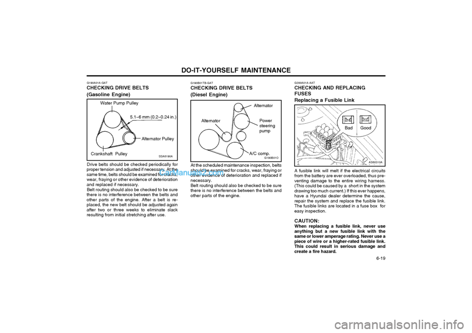
CHECKING DRIVE BELTS (Gasoline Engine)
Drive belts should be checked periodically for
proper tension and adjusted if necessary. At the same time, belts should be examined for cracks,wear, fraying or other evidence of deteriorationand replaced if necessary.
Belt routing should also be checked to be sure
there is no interference between the belts andother parts of the engine. After a belt is re-placed, the new belt should be adjusted againafter two or three weeks to eliminate slackresulting from initial stretching after use.
SSA6190A
Water Pump Pulley
Alternator Pulley
Crankshaft Pulley 5.1~6 mm (0.2~0.24 in.)
G200A01A-AAT
CHECKING AND REPLACING FUSES Replacing a Fusible Link
A fusible link will melt if the electrical circuits
from the battery are ever overloaded, thus pre- venting damage to the entire wiring harness.(This could be caused by a short in the systemdrawing too much current.) If this ever happens,have a Hyundai dealer determine the cause,repair the system and replace the fusible link.The fusible links are located in a fuse box foreasy inspection.
CAUTION: When replacing a fusible link, never use
anything but a new fusible link with the same or lower amperage rating. Never use apiece of wire or a higher-rated fusible link.This could result in serious damage andcreate a fire hazard.
AS60310A
Bad Good
G190B01TB-GAT
CHECKING DRIVE BELTS (Diesel Engine)
At the scheduled maintenance inspection, belts should be examined for cracks, wear, fraying orother evidence of deterioration and replaced ifnecessary. Belt routing should also be checked to be sure there is no interference between the belts andother parts of the engine.G190B01O
Power steeringpump
A/C comp.
Alternator
Alternator
Page 154 of 317
DO-IT-YOURSELF MAINTENANCE
6-20 CAUTION: A burned-out fuse indicates that there is aproblem in the electrical circuit. If you re-place a fuse and it blows as soon as theaccessory is turned on, the problem is seri-ous and should be referred to a Hyundaidealer for diagnosis and repair. Never re-place a fuse with anything except a fusewith the same or a lower amperage rating. Ahigher capacity fuse could cause damageand create a fire hazard.
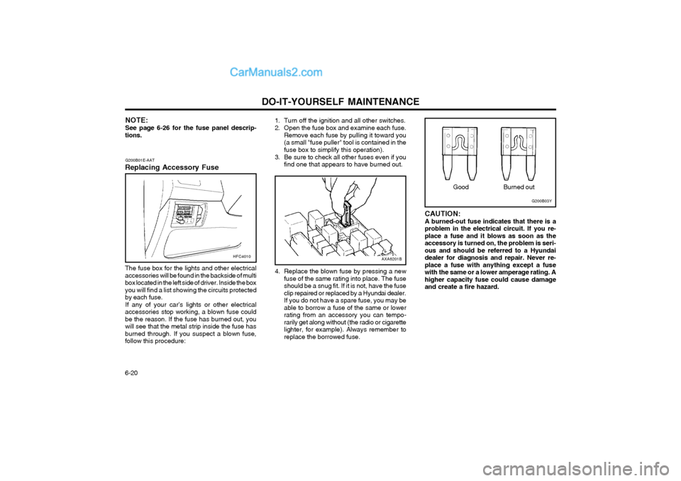
Burned out
G200B03YGood
4. Replace the blown fuse by pressing a new fuse of the same rating into place. The fuse should be a snug fit. If it is not, have the fuseclip repaired or replaced by a Hyundai dealer.If you do not have a spare fuse, you may beable to borrow a fuse of the same or lowerrating from an accessory you can tempo-rarily get along without (the radio or cigarettelighter, for example). Always remember toreplace the borrowed fuse.
AXA6201B
G200B01E-AAT
Replacing Accessory Fuse The fuse box for the lights and other electrical accessories will be found in the backside of multibox located in the left side of driver. Inside the boxyou will find a list showing the circuits protectedby each fuse. If any of your car’s lights or other electrical
accessories stop working, a blown fuse couldbe the reason. If the fuse has burned out, youwill see that the metal strip inside the fuse hasburned through. If you suspect a blown fuse,follow this procedure:
HFC4010
NOTE: See page 6-26 for the fuse panel descrip-
tions. 1. Turn off the ignition and all other switches.
2. Open the fuse box and examine each fuse.
Remove each fuse by pulling it toward you (a small "fuse puller" tool is contained in thefuse box to simplify this operation).
3. Be sure to check all other fuses even if you find one that appears to have burned out.
Page 160 of 317
DO-IT-YOURSELF MAINTENANCE
6-26
G200C02FC-GAT
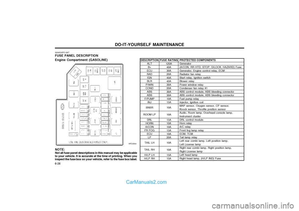
FUSE PANEL DESCRIPTION Engine Compartment (GASOLINE)
HFC4004
PROTECTED COMPONENTS Generator (A/CON, RR HTD, STOP, D/LOCK, HAZARD) Fuse Generator, Engine control relay, ECM Radiator fan relay Start relay, Ignition switch Blower relay Power window relay Condenser fan relay #1 ABS control module, ABS bleeding connector ABS control module, ABS bleeding connector Fuel pump relay Injector, lgnition coilMAP sensor, Oxygen sensor, CP sensor, Knock sensor, Throttle position sensor Audio, Room lamp, Overhead console lamp, lnstrument cluster DRL control module Horn relay A/C relay Front fog lamp relay ECM, TCM Tail lamp relay Left rear combi lamp, Left position lamp, Left License lamp Right rear combi lamp, Right position lamp, Right License lamp Left head lamp Right head lamp, (H/LP IND) Fuse
FUSE RATING
120A40A30A 20A 40A 40A 30A 20A 30A 30A 10A 15A 10A 10A 15A 10A 10A 15A 10A 20A 10A 10A 15A 15A
DESCRIPTION
ALTB+
ECU RAD IGN
BLR
P/WINCOND ABSABS
F/PUMP INJ
SNSR
ROOM LP DRL
HORN
A/CON
FR FOG ECU
LP
TAIL LH
TAIL RH H/LP LH
H/LP RH
NOTE:
Not all fuse panel descriptions in this manual may be applicable
to your vehicle. It is accurate at the time of printing. When you inspect the fuse box on your vehicle, refer to the fuse box label.
Page 161 of 317
DO-IT-YOURSELF MAINTENANCE 6-27
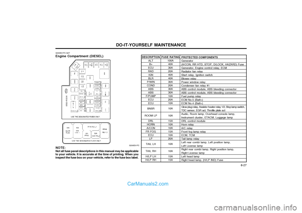
DESCRIPTION
ALTB+
ECU RAD IGN
BLR
P/WINCOND ABSABS
F/PUMP ECU ECU
SNSR
ROOM LP DRL
HORN
A/CON
FR FOG
ECULP
TAIL LH
TAIL RH H/LP LH
H/LP RH
G200E01FC-GAT
Engine Compartment (DIESEL)
G200E01FCPROTECTED COMPONENTS Generator (A/CON, RR HTD, STOP, D/LOCK, HAZARD) Fuse Generator, Engine control relay, ECM Radiator fan relay Start relay, Ignition switch Blower relay Power window relay Condenser fan relay #1 ABS control module, ABS bleeding connector ABS control module, ABS bleeding connector Fuel pump relay ECM No.5 (Batt+) ECM No.4 (Batt+)
Glow plug r elay, Assistor h eater relay 1/2, Stop lamp switch,
TDC sensor, EGR act, Throttle plate a ct
Audio, Room lamp, Overhead console lamp, lnstrument cluster, ETACM, Luggage lamp DRL control module Horn relay A/C relay Front fog lamp relay ECM, TCM Tail lamp relay Left rear combi lamp, Left position lamp, Left License lamp Right rear combi lamp, Right position lamp, Right License lamp Left head lamp Right head lamp, (H/LP IND) Fuse
FUSE RATING
100A40A 30A 20A 40A 40A 30A 20A 30A 30A 10A 20A 10A 10A 10A 15A 10A 10A 15A 10A 20A 10A 10A 15A 15A
NOTE:
Not all fuse panel descriptions in this manual may be applicable
to your vehicle. It is accurate at the time of printing. When you inspect the fuse box on your vehicle, refer to the fuse box label.
Page 172 of 317
INDEX
10-2 Driving
Economical dr iving ........................................................................ 2-10
Smooth cornering .......................................................................... 2-10
Winter driving ................................................................................ 2-10
E Emissions Control Systems ................................................................ 7-1
Engine Before starting the engine ............................................................... 2-2Compartment .......................................................................... 6-1 ~ 6-3
Coolant ................................................................................. 6-8 ~ 6-10
Coolant temperature gauge ........................................................... 1-36
If the engine overheats ................................................................... 3-2
Number ............................................................................................ 8-1
Oil ........................................................................................... 6-4 ~ 6-5Starting ............................................................................................ 2-3
Engine Exhaust Can Be Dangerous ................................................... 2-1
FFold-up Tray ...................................................................................... 1-50
Front Fog Light Sw itch ...................................................................... 1-42
Front Seats Adjustable front seats ..................................................................... 1-9
Lumbar support control ................................................................. 1-10
Seat cushion height adjustment .................................................... 1-10
Fuel Capacity .......................................................................................... 9-1
Gauge ............................................................................................ 1-36
Recommendations ........................................................................... 1-1
Fuel Filler Lid
Remote release ............................................................................. 1-52
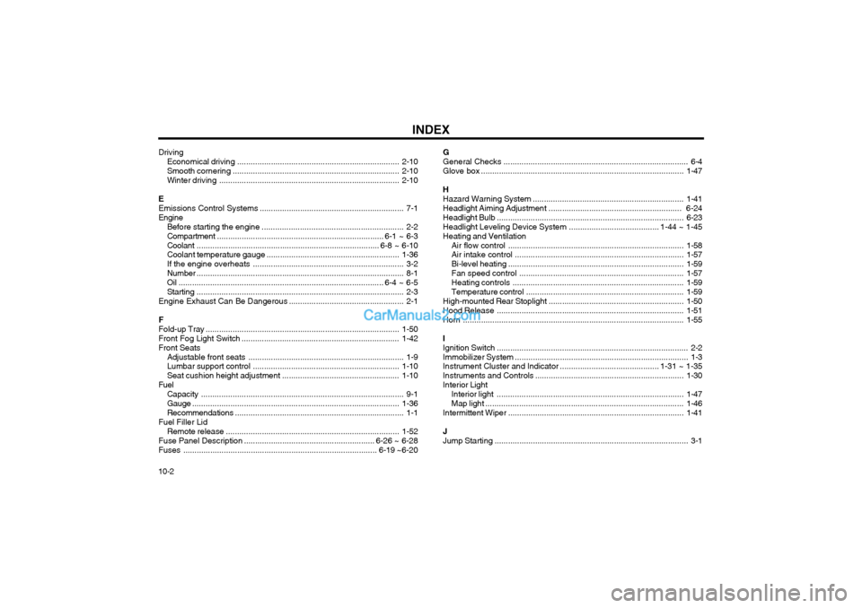
Fuse Panel Description .......................................................... 6-26 ~ 6-28
Fuses ...................................................................................... 6-19 ~6-20 GGeneral Checks
.................................................................................. 6-4
Glove box .......................................................................................... 1-47
H Hazard Warning System ................................................................... 1-41
Headlight Aiming Adjustment ........................................................... 6-24
Headlight Bulb ................................................................................... 6-23
Headlight Leveling Device System ........................................ 1-44 ~ 1-45
Heating and Ventilation
Air flow control .............................................................................. 1-58
Air intake control ........................................................................... 1-57
Bi-level heating .............................................................................. 1-59
Fan speed control ......................................................................... 1-57
Heating controls ............................................................................ 1-59
Temperature control ...................................................................... 1-59
High-mounted Rear Stoplight ............................................................ 1-50
Hood Release ................................................................................... 1-51
Horn .................................................................................................. 1-55
IIgnition Switch ..................................................................................... 2-2
Immobilizer System ............................................................................. 1-3
Instrument Cluster and Indicator ............................................ 1-31 ~ 1-35
Instruments and Controls .................................................................. 1-30
Interior Light Interior light ................................................................................... 1-47
Map light ........................................................................................ 1-46
Intermittent Wiper .............................................................................. 1-41
JJump Starting ...................................................................................... 3-1
Page 227 of 317
1- 45
CONTROLS AND EQUIPMENT
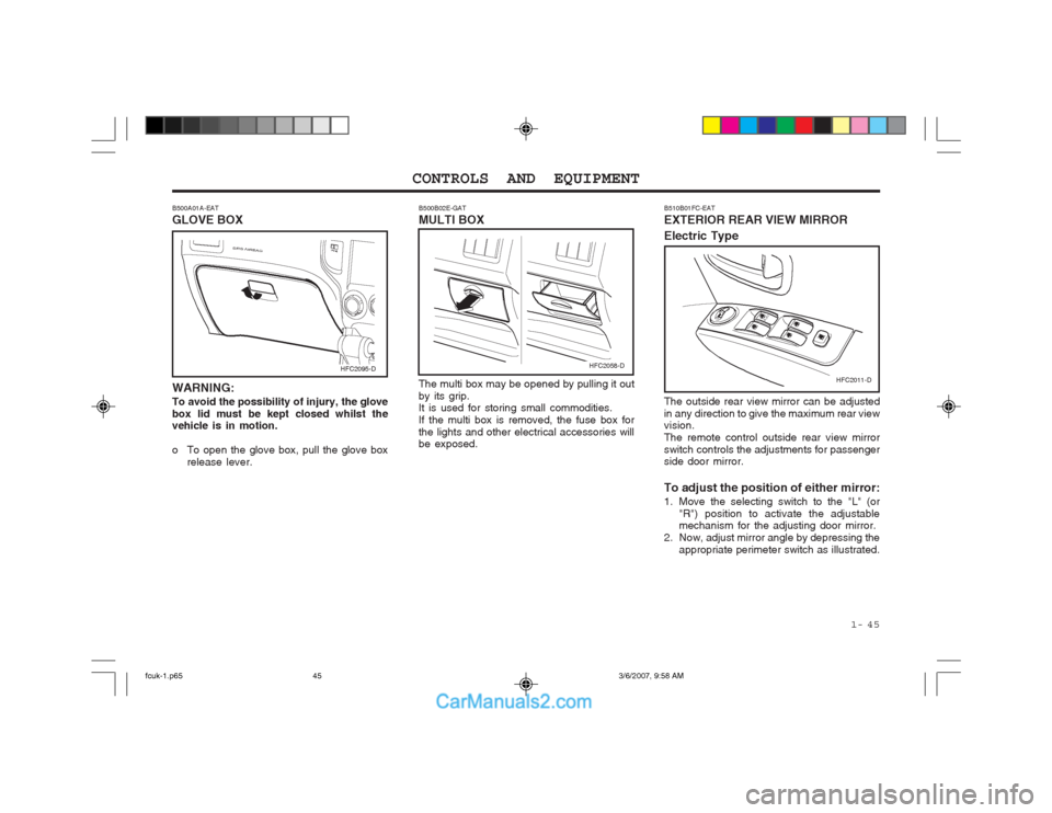
B500A01A-EAT GLOVE BOX WARNING: To avoid the possibility of injury, the glove box lid must be kept closed whilst the vehicle is in motion.
o To open the glove box, pull the glove box release lever. The multi box may be opened by pulling it out by its grip. It is used for storing small commodities. If the multi box is removed, the fuse box forthe lights and other electrical accessories will be exposed.
B500B02E-GAT MULTI BOX
HFC2095-DHFC2058-D
HFC2011-D
B510B01FC-EAT EXTERIOR REAR VIEW MIRROR Electric Type The outside rear view mirror can be adjusted in any direction to give the maximum rear view vision. The remote control outside rear view mirrorswitch controls the adjustments for passenger side door mirror. To adjust the position of either mirror:
1. Move the selecting switch to the "L" (or
"R") position to activate the adjustable mechanism for the adjusting door mirror.
2. Now, adjust mirror angle by depressing the appropriate perimeter switch as illustrated.
fcuk-1.p65 3/6/2007, 9:58 AM
45
Page 296 of 317
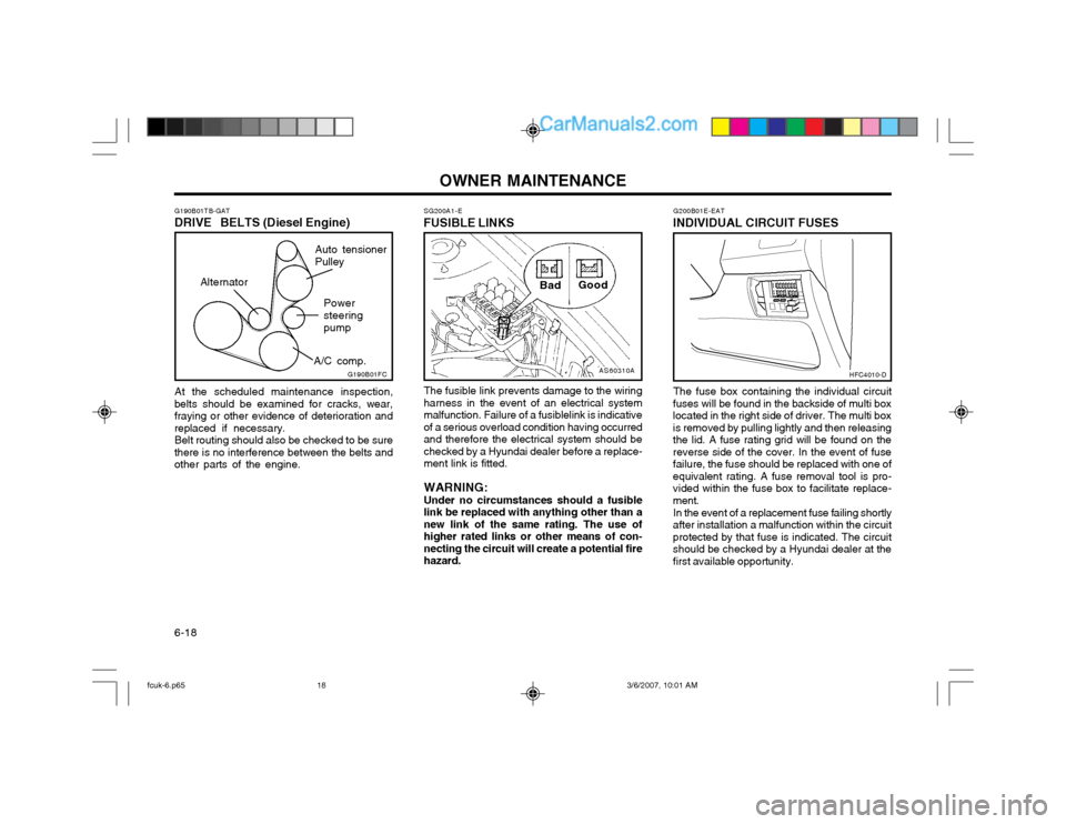
OWNER MAINTENANCE
6-18 G200B01E-EAT
INDIVIDUAL CIRCUIT FUSES
The fuse box containing the individual circuit
fuses will be found in the backside of multi box located in the right side of driver. The multi boxis removed by pulling lightly and then releasingthe lid. A fuse rating grid will be found on thereverse side of the cover. In the event of fusefailure, the fuse should be replaced with one ofequivalent rating. A fuse removal tool is pro-vided within the fuse box to facilitate replace-ment.
In the event of a replacement fuse failing shortly
after installation a malfunction within the circuitprotected by that fuse is indicated. The circuitshould be checked by a Hyundai dealer at thefirst available opportunity.
HFC4010-D
SG200A1-E
FUSIBLE LINKSAS60310A
Bad
Good
The fusible link prevents damage to the wiring harness in the event of an electrical systemmalfunction. Failure of a fusiblelink is indicativeof a serious overload condition having occurredand therefore the electrical system should bechecked by a Hyundai dealer before a replace-ment link is fitted. WARNING: Under no circumstances should a fusible link be replaced with anything other than anew link of the same rating. The use ofhigher rated links or other means of con-necting the circuit will create a potential firehazard.
G190B01TB-GAT DRIVE BELTS (Diesel Engine)
At the scheduled maintenance inspection,
belts should be examined for cracks, wear, fraying or other evidence of deterioration andreplaced if necessary. Belt routing should also be checked to be sure
there is no interference between the belts andother parts of the engine.G190B01FC
Auto tensioner Pulley
Powersteeringpump
A/C comp.
Alternator
fcuk-6.p65
3/6/2007, 10:01 AM
18
Page 303 of 317
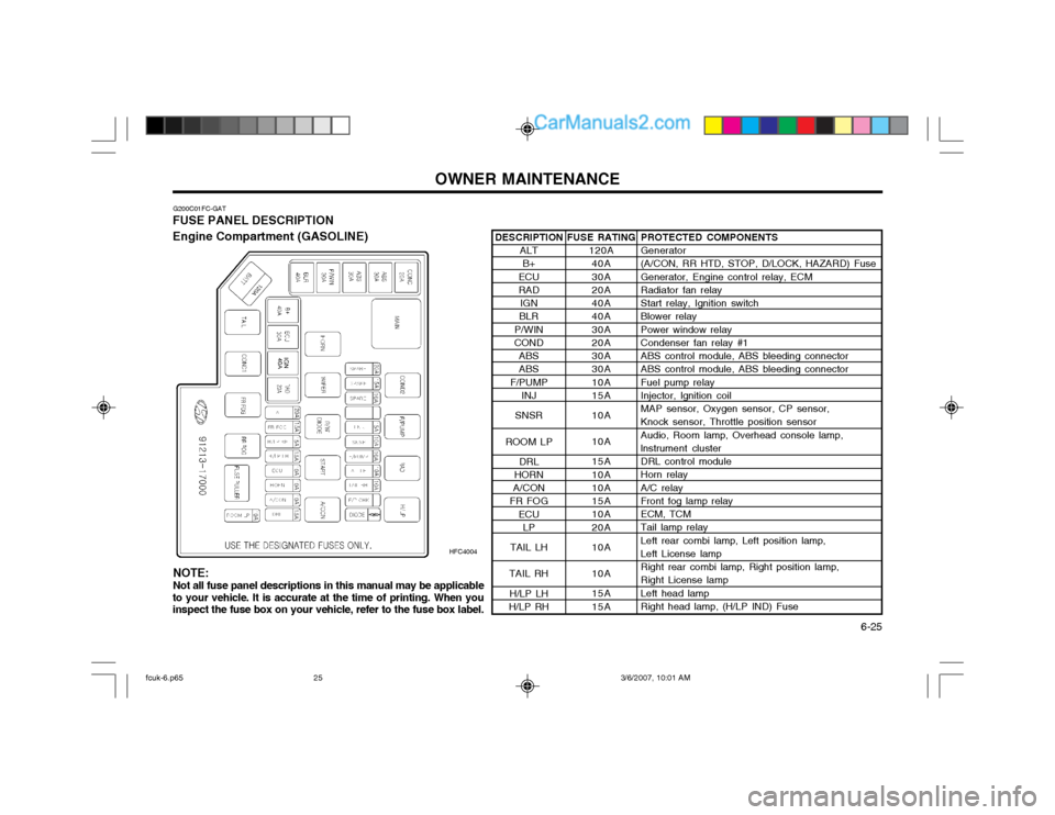
OWNER MAINTENANCE 6-25
G200C01FC-GAT
FUSE PANEL DESCRIPTION Engine Compartment (GASOLINE)
HFC4004PROTECTED COMPONENTS Generator (A/CON, RR HTD, STOP, D/LOCK, HAZARD) Fuse Generator, Engine control relay, ECM Radiator fan relay Start relay, Ignition switch Blower relay Power window relay Condenser fan relay #1 ABS control module, ABS bleeding connector ABS control module, ABS bleeding connector Fuel pump relay Injector, lgnition coil MAP sensor, Oxygen sensor, CP sensor, Knock sensor, Throttle position sensor Audio, Room lamp, Overhead console lamp, lnstrument cluster DRL control module Horn relay A/C relay Front fog lamp relay ECM, TCM Tail lamp relay Left rear combi lamp, Left position lamp, Left License lamp Right rear combi lamp, Right position lamp, Right License lamp Left head lamp Right head lamp, (H/LP IND) Fuse
FUSE RATING
120A40A 30A 20A 40A 40A 30A 20A 30A 30A 10A 15A 10A 10A 15A 10A 10A 15A 10A 20A 10A 10A 15A 15A
DESCRIPTION
ALTB+
ECU RAD IGN
BLR
P/WIN
COND
ABSABS
F/PUMP INJ
SNSR
ROOM LP DRL
HORN
A/CON
FR FOG
ECULP
TAIL LH
TAIL RH H/LP LH
H/LP RH
NOTE: Not all fuse panel descriptions in this manual may be applicable
to your vehicle. It is accurate at the time of printing. When you inspect the fuse box on your vehicle, refer to the fuse box label.
fcuk-6.p65 3/6/2007, 10:01 AM
25