tow Hyundai Matrix 2005 User Guide
[x] Cancel search | Manufacturer: HYUNDAI, Model Year: 2005, Model line: Matrix, Model: Hyundai Matrix 2005Pages: 407, PDF Size: 10.31 MB
Page 47 of 407
1- 39
CONTROLS AND EQUIPMENT
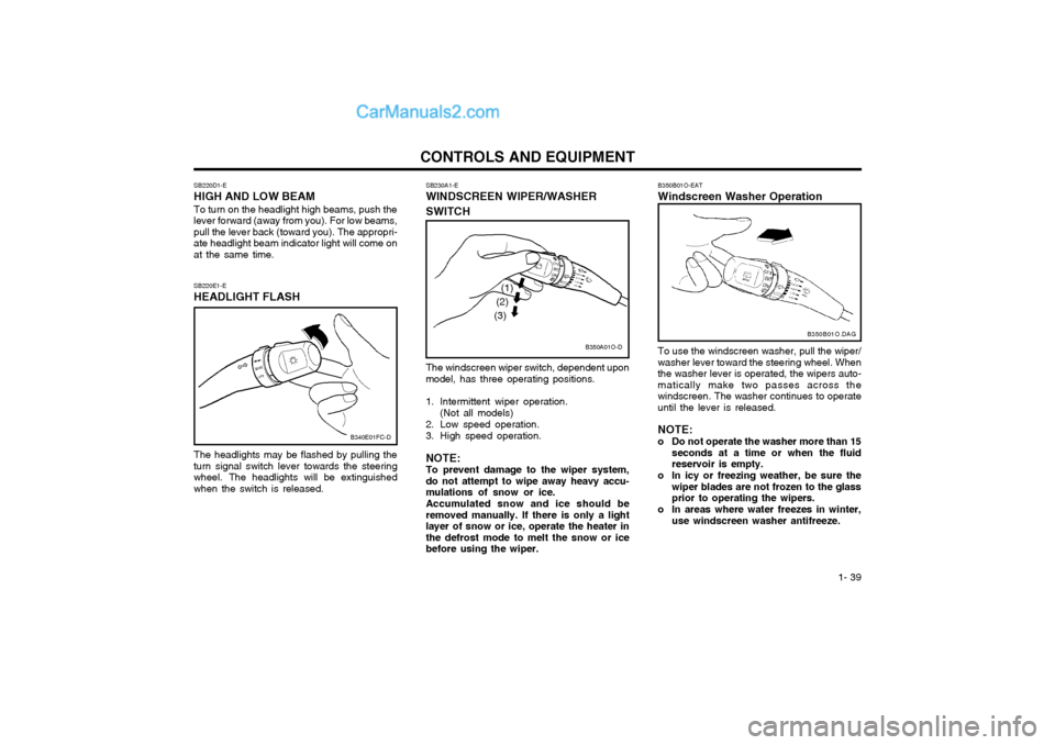
The windscreen wiper switch, dependent upon model, has three operating positions.
1. Intermittent wiper operation.(Not all models)
2. Low speed operation.
3. High speed operation. NOTE: To prevent damage to the wiper system,do not attempt to wipe away heavy accu-mulations of snow or ice. Accumulated snow and ice should be removed manually. If there is only a lightlayer of snow or ice, operate the heater inthe defrost mode to melt the snow or icebefore using the wiper.
SB230A1-E WINDSCREEN WIPER/WASHER SWITCH
SB220E1-E HEADLIGHT FLASH The headlights may be flashed by pulling the turn signal switch lever towards the steeringwheel. The headlights will be extinguishedwhen the switch is released.
SB220D1-E HIGH AND LOW BEAM To turn on the headlight high beams, push the lever forward (away from you). For low beams,pull the lever back (toward you). The appropri-ate headlight beam indicator light will come onat the same time.
B340E01FC-D
B350A01O-D
(1)
(2)
(3)
B350B01O-EAT Windscreen Washer Operation To use the windscreen washer, pull the wiper/ washer lever toward the steering wheel. Whenthe washer lever is operated, the wipers auto-matically make two passes across thewindscreen. The washer continues to operateuntil the lever is released. NOTE:
o Do not operate the washer more than 15 seconds at a time or when the fluid reservoir is empty.
o In icy or freezing weather, be sure the wiper blades are not frozen to the glassprior to operating the wipers.
o In areas where water freezes in winter, use windscreen washer antifreeze. B350B01O.DAG
Page 56 of 407

CONTROLS AND EQUIPMENT
1- 48
SB360C1-F FOLDING THE OUTSIDE REAR VIEW MIRRORS To fold the outside rear view mirrors, push them towards the rear. The outside rear view mirrors can be folded rearward for parking in restricted areas. WARNING: Do not adjust or fold the outside rear view mirrors whilst the vehicle is moving. Thiscould result in loss of control, and anaccident causing death, serious injury orproperty damage.
B510D01E
CAUTION:
o Do not leave the switch on for an unnecessary length of time.
o Scraping ice from the mirror face could cause permanent damage. To remove any ice, use a sponge, soft cloth orapproved deicer.
o Be careful when judging the size or dis- tance of any object seen in the passen-ger side rear view mirror. It is a convexmirror with a curved surface, any ob-jects seen in this mirror are closer thanthey appear.
B510C01FC-D
B510D01HP-EAT OUTSIDE REARVIEW MIRROR HEATER (Not all models)
The outside rearview mirror heater is actuated in connection with the rear window defroster.To heat the outside rearview mirror glass,push in the switch for the rear window de-froster. The rearview mirror glass will be heatedfor defrosting or defogging and will give youimproved rear vision in inclement weatherconditions. Push the switch again to turn theheater off. The outside rearview mirror heaterautomatically turns itself off after 20 minutes. HFC2080-D
Page 57 of 407
1- 49
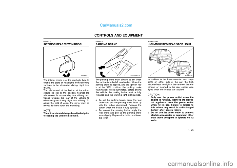
CONTROLS AND EQUIPMENTSB380A1-E PARKING BRAKE The parking brake must always be set when the vehicle is to be left unattended. When theparking brake is applied, and the ignition keyis at the "ON" position, the parking brakewarning light will be illuminated. Before drivingthe vehicle, the parking brake must be fullyreleased and the warning light extinguished.
o To set the parking brake, apply the foot brake and pull the parking brake lever up with the button depressed. Release thebutton when the brake is fully applied.
o To release the parking brake, apply the foot brake and pull up the parking brakelever slightly. Depress the button and lowerthe lever.
SB370A1-E
INTERIOR REAR VIEW MIRROR
The interior mirror is of the day/night type to
enable the glare of headlights from followingvehicles to be eliminated during night timedriving.
The tab located at the bottom of the mirror
should be set to the position nearest thewindscreen for normal day time driving, andflipped towards the rear of the vehicle toeliminate glare during night time driving. Toadjust the field of vision, the mirror may bemoved by hand upon the mounting.
NOTE:The mirror should always be adjusted prior
to setting the vehicle in motion.
B530A01FC-DB550A01FC
B520A01E
B550A01S-DAT
HIGH-MOUNTED REAR STOP LIGHT
In addition to the lower-mounted rear stop-
lights on either side of the car, the high
mounted rear stoplight in the centre of the rearwindow or inserted in the rear spoiler alsolights when the brakes are applied. CAUTION:
o Only use the power outlet when the engine is running. Remove the electri-cal appliance from the power outletwhen not in use. Failure to adhere tothis advice may result in a dischargedbattery after several hours.
o Do not use the power outlet to connect electric accessories or equipment otherthan those designed to operate on 12volts.
Page 59 of 407

1- 51
CONTROLS AND EQUIPMENT
B570A01FC-EAT
BONNET RELEASE
Pull the release lever inside the vehicle to
unlatch the bonnet. At the front of the vehicle, push the safety catch lever sidewards asshown and raise the bonnet by hand. Supportthe bonnet by means of the bonnet prop. Before closing the bonnet, ensure that the
prop is correctly stowed. Lower the bonnet byhand to a position of approximately 30cm fromthe closed position and allow the bonnet todrop. Do not attempt to close the bonnet bylowering the panel to the closed position andpressing upon the panel work since this mayresult in damage to the panel. CAUTION:Ensure that the bonnet prop has beenremoved prior to closing the bonnet. Al-ways check to ensure that the bonnet haslatched prior to setting the vehicle in mo-tion. WARNING: The bonnet prop must be correctly in- serted into the panel to prevent the possi-bility of injury arising from the bonnetfalling.
HFC2019
HFC2018-D
SB440A1-E
REMOTE FUEL FILLER FLAP
RELEASE (Not all models) The fuel filler flap may be opened from inside
the vehicle by pulling up on the fuel filler flap release.
NOTE: If the fuel filler flap will not open because
ice has formed around it, tap lightly or push on it to break the ice and release it.Do not lever the flap. If necessary, sprayaround the flap with an approved deicerfluid (do not use radiator anti-freeze) ormove the vehicle to a warm place andallow the ice to melt.
HFC2015-D
Page 62 of 407
CONTROLS AND EQUIPMENT
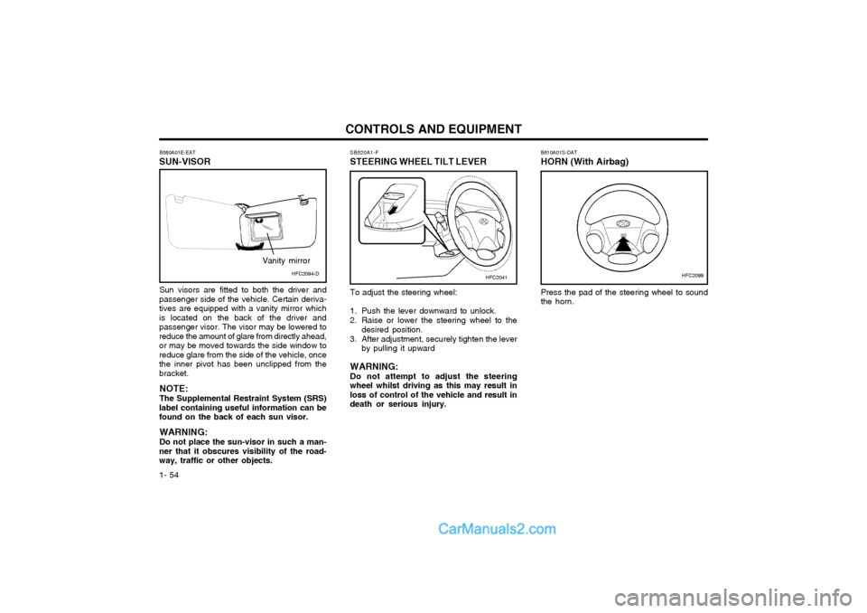
1- 54 B610A01S-DAT HORN (With Airbag) Press the pad of the steering wheel to sound the horn.
B580A01E-EAT
SUN-VISOR
Sun visors are fitted to both the driver and
passenger side of the vehicle. Certain deriva-tives are equipped with a vanity mirror whichis located on the back of the driver andpassenger visor. The visor may be lowered toreduce the amount of glare from directly ahead,or may be moved towards the side window toreduce glare from the side of the vehicle, oncethe inner pivot has been unclipped from thebracket.
NOTE: The Supplemental Restraint System (SRS)
label containing useful information can be found on the back of each sun visor.
WARNING: Do not place the sun-visor in such a man-
ner that it obscures visibility of the road- way, traffic or other objects. SB520A1-F
STEERING WHEEL TILT LEVER
HFC2099HFC2041HFC2094-D
Vanity mirror
To adjust the steering wheel:
1. Push the lever downward to unlock.
2. Raise or lower the steering wheel to the
desired position.
3. After adjustment, securely tighten the lever by pulling it upward
WARNING: Do not attempt to adjust the steeringwheel whilst driving as this may result inloss of control of the vehicle and result indeath or serious injury.
Page 68 of 407
CONTROLS AND EQUIPMENT
1- 60 B740C01FC-GAT
Dehumidified Heating
B740C01FC
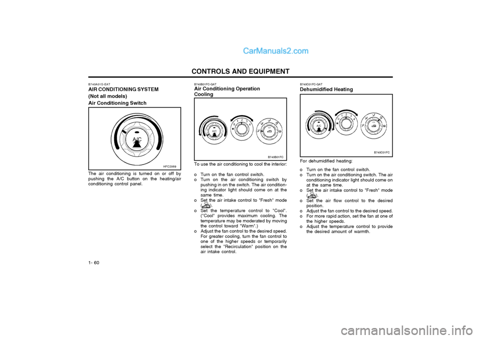
For dehumidified heating:
o Turn on the fan control switch.
o Turn on the air conditioning switch. The air conditioning indicator light should come on at the same time.
o Set the air intake control to "Fresh" mode (
).
o Set the air flow control to the desired position.
o Adjust the fan control to the desired speed.
o For more rapid action, set the fan at one of the higher speeds.
o Adjust the temperature control to provide the desired amount of warmth.
B740B01FC-GAT Air Conditioning Operation Cooling
B740B01FC
To use the air conditioning to cool the interior:
o Turn on the fan control switch.
o Turn on the air conditioning switch by pushing in on the switch. The air condition-ing indicator light should come on at thesame time.
o Set the air intake control to "Fresh" mode (
).
o Set the temperature control to "Cool". ("Cool" provides maximum cooling. The temperature may be moderated by movingthe control toward "Warm".)
o Adjust the fan control to the desired speed. For greater cooling, turn the fan control toone of the higher speeds or temporarilyselect the "Recirculation" position on theair intake control.
B740A01S-EAT AIR CONDITIONING SYSTEM (Not all models)Air Conditioning Switch
The air conditioning is turned on or off by pushing the A/C button on the heating/airconditioning control panel. HFC2069
Page 70 of 407

CONTROLS AND EQUIPMENT
1- 62
FM broadcasts are transmitted at high fre- quency and do not bend to follow the earth'ssurface. Because of this, FM broadcasts gen-erally begin to fade at short distances from thestation. Also, FM signals are easily affected bybuildings, mountains, or other obstructions.These can result in certain listening conditionswhich might lead you to believe a problemexists with your radio. The following conditionsare normal and do not indicate radio trouble:
Buildings
Obstructed area
Unobstructed area
FM radio station
SSAR012A
Mountains
Iron bridges
B750A02A-AAT STEREO SOUND SYSTEM How Car Audio Works
IonosphereFM reception
SSAR010A
AM and FM radio signals are broadcast from transmitter towers located around your city.They are intercepted by the radio antenna onyour car. This signal is then received by theradio and sent to your car speakers.When a strong radio signal has reached yourvehicle, the precise engineering of your audiosystem ensures high quality reproduction. How-ever, in some cases the signal coming to yourvehicle is not strong and clear. This can be dueto factors such as the distance from the radiostation, closeness of other strong radio stationsor the presence of buildings, bridges and otherlarge obstructions in the area.
Ionosphere
SSAR011A
AM reception
AM broadcasts can be received at greater distances than FM broadcasts. This is becauseAM radio waves are transmitted at low fre-quency. These long, low frequency radio wavescan follow the curvature of the earth rather thantravelling straight out into the atmosphere. Inaddition, they curve around obstructions sothat they can provide better signal coverage.
Page 81 of 407
DRIVING YOUR HYUNDAI 2- 9
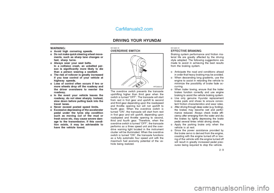
SC130A1-E OVERDRIVE SWITCH
The overdrive switch prevents the transaxle upshifting higher than third gear when the switch is turned "OFF". The transaxle will start from rest in first gear and upshift to second and third gear depending upon the roadspeed and throttle opening but will not upshift to fourth gear. When the overdrive switch is turned "ON", the transaxle will start from rest in first gear and will upshift, depending upon roadspeed and throttle opening to second, third and fourth gear. Therefore, when the overdrive switch is turned "OFF", the transaxle performs as a three speed unit and the over- drive warning light located in the instrument cluster will be illuminated. When the overdrive switch is turned "ON", the transaxle functions as a fully automatic four speed unit with the maximum fuel economy potential of the ve- hicle being realized.
SC140A1-E EFFECTIVE BRAKINGBraking system performance and friction ma- terial life are greatly affected by the driving style adopted. The following suggestions are made to assist in achieving the best results from the braking system.
o Anticipate the road and conditions ahead
in order that heavy braking may be avoided.
o When descending long gradients, use the engine to assist in retarding the vehicle to minimize the possibility of brake fade oc- curring.
o When trailer towing, ensure that the trailer brakes function correctly and use enginebraking to assist the vehicle braking system.
o Use only genuine Hyundai replacement brake pads and shoes to ensure consis-tent friction characteristics and wear rates.
o After driving through deep water (e.g. fording), the brakes may become wet and perfor-mance reduced. Always check brake effi- ciency after emerging from the water and dry the brakes by lightly depressing the brake pedal several times whilst driving slowly.
o Apply the parking brake only when the
vehicle is at rest.
o Since the power assistance provided by
the brake servo is derived from the engine,coasting with the engine turned off or tow- ing of the vehicle with the engine turned off will result in greatly increased pedal pres- sures being required to stop the vehicle.
HFC3023-D
WARNING:
o Avoid high cornering speeds.
o Do not make quick steering wheel move-ments, such as sharp lane changes orfast, sharp turns.
o Always wear your seat belts. In a collision crash, an unbelted per- son is significantly more likely to die than a person wearing a seatbelt.
o The risk of rollover is greatly increased if you lose control of your vehicle athighway speeds.
o Loss of control often occurs if two or more wheels drop off the roadway andthe driver oversteers to reenter the roadway.
o In the event your vehicle leaves the roadway, do not steer sharply. Instead,slow down before pulling back into the travel lanes.
o Never exceed posted speed limits.
o Excessive depressing of the accelerater
pedal under the tyres slip condition such as moving out of the mud or fresh snow etc, may cause severe dam- age to the transmission. If this condi- tion exists, it may be adviseable to have the vehicle towed.
Page 85 of 407
DRIVING YOUR HYUNDAI 2- 13
NOTE: Never allow undiluted screen washer fluidadditive to spill upon the paintwork or use engine coolant anti-freeze since damage to the paintwork may result.
o When driving in extreme conditions, the
windscreen wiper blades may fail to clear the screen properly due to the formation of ice upon the blade edge. It will therefore be necessary to periodically remove such ice to restore their efficiency.
o If the power operated door mirrors become frozen, attempts to adjust these may dam-age the mechanism.
o The formation of snow or ice built up inside the wheel arches may interfere with theroad wheels or steering mechanism. In such instances, unusual noises or an in- crease in steering effort may result. There- fore, ensure that the wheel arches are checked periodically and any accumulated snow or ice removed.
o It is advisable to carry emergency equip- ment including, torch, shovel, tow rope,blankets etc., if a journey is to be under- taken into areas of severe road conditions. SC200B3-E
TOWING ATTACHMENTS It is strongly recommended that only an
Hyundai Approved towing attachment is usedto ensure that the loads placed upon the body structure are correctly distributed. The use of a non approved attachment will result in the invalidation of the vehicle warranty. Hyundai towing attachments are designed and con- structed to ensure maximum towing perfor- mance and ease of fitment. A range of acces- sories including electrical kits are available through the Hyundai authorised repairer net- work.
It is of the utmost importance that those areas
of the vehicle which are subjected to greaterstress during towing are maintained in accor- dance with the recommendations given at the end of this book. In addition, the daily operating checks relating to engine oil, transmission oil and tyres must be performed at each refuelling to ensure maximum reliability and safety. The use of a proprietary stabiliser will assist in
achieving an inherently stable outfit but whilstthe use of such equipment will improve the characteristics of a balanced outfit, it will not compensate for a badly loaded and therefore unstable outfit.
The tyres and braking equipment fitted to the
trailer or caravan must be maintained in ac- cordance with the recommendations of the manufacturer. Special attention should be paid
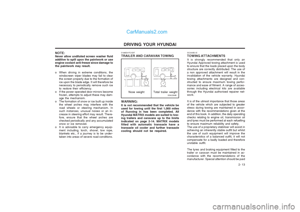
WARNING: It is not recommended that the vehicle be used for towing until the first 1,000 miles of Running in has been completed. All Hyundai MATRIX models are suited to tow- ing trailers and caravans up to the limits indicated on page 2-14. MATRIX models fitted with automatic transaxle have a transaxle oil cooler and further transaxle cooling should not be required.
C190E01FC-EAT TRAILER AND CARAVAN TOWING
Nose weightSSA2200B
Total trailer weight
Page 86 of 407
DRIVING YOUR HYUNDAI
2- 14 NOTE:
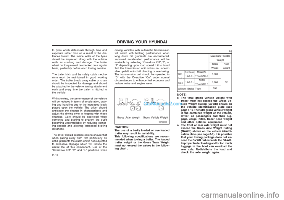
o The total gross vehicle weight with trailer must not exceed the Gross Ve- hicle Weight Rating (GVWR) shown on the vehicle identification plate (see page 8-1). The total gross vehicle weight is the combined weight of the vehicle, driver, all passengers and their lug- gage, cargo, hitch, trailer nose weight and other optional equipment.
o The front or rear axle weight must not exceed the Gross Axle Weight Rating(GAWR) shown on the vehicle identifi- cation plate (see page 8-1). it is possible that your towing package does not ex- ceed the GVWR but exceeds the GAWR. Improper trailer loading and/or too much luggage in the boot can overload the rear axle. Redistribute the load and check the axle weight again. MANUAL
TRANSAXLE AUTO
TRANSAXLE Trailer
Weight
1,300 1,100 550 Nose
weight
52
kg
Maximum Towable Weight
With Brake Type
1.5 Diesel 1.6/1.8 L
1.6/1.8 L
Without Brake Type
driving vehicles with automatic transmission will assist with braking performance when long down hill gradients are encountered. Improved acceleration performance will be available by selecting "Overdrive Off","2", or "1" depending upon road speed if it is found that the transmission unit makes an undesir- able upshift whilst hill climbing or overtaking. The transmission unit should be operated in "D" with the Overdrive "On" under normal circumstances to enhance fuel economy and reduce noise and engine wear.
Gross Axle Weight
CAUTION: The use of a badly loaded or overloaded trailer may result in instability. This following specifications are recom-mended when towing a trailer. The loaded trailer weight or the Gross Train Weight must not exceed the values in the follow- ing chart . SSA2200DGross Vehicle Weight
to tyres which deteriorate through time and exposure rather than as a result of the dis- tances towed. The inside walls of the tyres should be inspected along with the outside walls for cracking and damage. The trailer wheel nut torque must be checked on a regular basis, preferably before each towing session. The trailer hitch and the safety catch mecha- nism must be maintained in good working order. The trailer break away cable or chain should be inspected for damage and should be attached to the vehicle towing attachment each and every time the trailer is hitched to the vehicle. Whilst towing, the performance of the vehicle will be reduced in terms of acceleration, brak- ing and handling due to the increased loads placed upon the vehicle. The driver should anticipate the change in characteristics and adjust the driving style in keeping with these changes. Care should be exercised when cornering and braking to prevent the outfit becoming uncontrollable by reducing corner- ing speeds and allowing increased braking distances. The driver should exercise care to ensure that when pulling away from rest particularly on uphill gradients the clutch unit is not subjected to excessive slippage which will reduce the useful life of this component. Use of the "Overdrive Off" "2" and "L" positions when